![]() Pull Station Fire Alarm
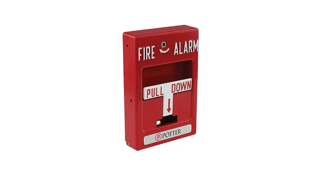
Pull Station Fire Alarm
Instruction Manual
Installation and Service

Installers Note:
The station are supplied with glass rod removed. It is recommended that the station be activated and tested prior to installation of the glass rod.
- Glass Rods and Hardware are shipped with station box.
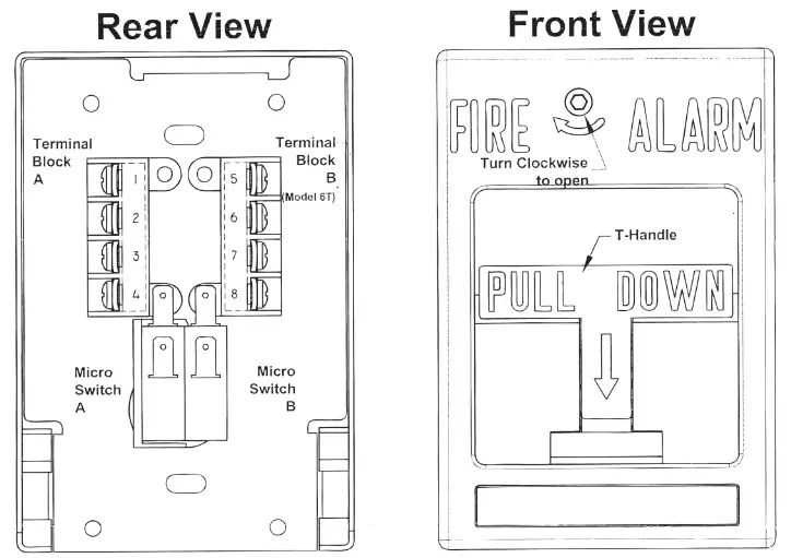
Replacement o Glass Rod:
If broken, remove debris, then reset T-Handle to normal position. Onsert one end of new Glass Rod under Spring Tab, then with one finger, lift other end os Spring tab allowing Glass Rod to slip into place.
To Close Station:
If hex Screw Model, simply push station closed. If Key Lock Model, hold station closed then turn key counterclockwise.
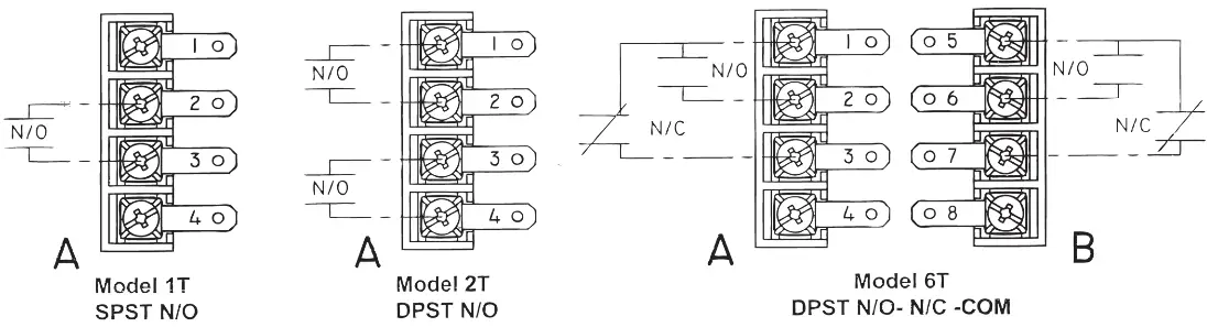
Electrical Wiring
| Model | Terminal Block | Terminal Connecting | Switch Function | Terminal Connection | Contact Rating | ||
| LED | Switch | Ph. Jack | |||||
| 1P | None | None | SPST | Leeds | Leeds | Leeds | 10 amp @ 125 vac |
| 1T | A | 2 – 3 | SPST | 1(+) – 4(-) | 1 – 4 | 1 – 4 | 10 amp @ 125 vac |
| 2T | A | 1-2 & 3-4 | DPST | 5(+)- 6(-) | 5 – 6 | 5 – 6 | 10 amp @ 125 vac |
| 3T | A | 1,2, & 3 | SPDT | 5(+)- 6(-) | 5 – 6 | 5 – 6 | 10 amp @ 125 vac |
| 6T | A & B | 1,2,3,5,6,7 | DPDT | 4(+) – 8(-) | 4 – 8 | 4 – 8 | 10 amp @ 125 vac |
Note: all contact ratings shown apply to closed station.
![]() Phone Jack: 1/4
Phone Jack: 1/4
Key Switch: 3Amp©125Vac
Led: 1-1-3/4@24Vdc
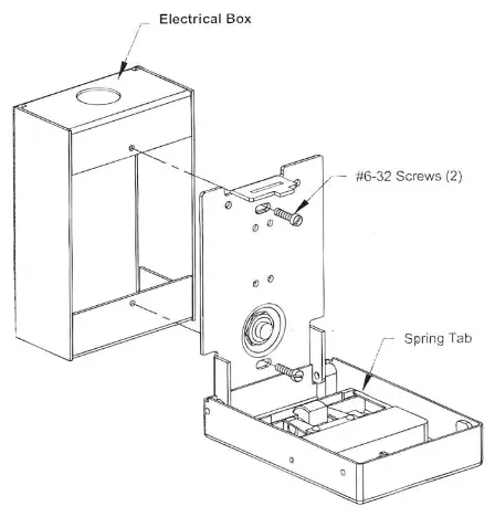
Mounting Instructions on Reverse Side
firealarmresources.com


