![]() ASB
ASB
AddreSSABle Sounder BASe
![]() Product includes a 5 year warranty
Product includes a 5 year warranty
Features
- Integrated Sounder in base
- 75 dB (UL 464 Listed) sounder output
- 85 dBA (ULC Listed) sounder output
- Sounder independent of sensor, allows for a single station, grouped or all-call
- May be mapped to any device connected to the control panel
- Maximum standby, 325 µA
- Maximum alarm current, 100 mA (aux power)
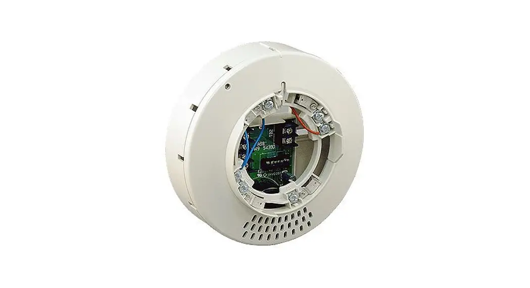
Description
The Addressable Sounder Base 6” (ASB) is a sounder base that may be utilized in a variety of applications. The base has a locking feature for the sensor that may be used or removed in the field. Once the head is removed, the sounder is accessible in the bottom of the unit.
The base has an independent sounder module that may be programmed as a single station, zone or all call sounder. The sounder produces a minimum of 75 dB at 10 feet. The ASB passes through the sound pattern sent to the sounder, therefore it may reproduce in any pattern the power supply provides.
The panel will support any combination of sensors or modules on the SLC. The ASB occupies one address on the loop and is fully programmable to operate with any input. Once activated the sounder will also follow the input from the power source and deactivate accordingly.
Detector Base Mounting
ASB should be mounted directly on the electrical box. The mounting holes are configured for a single gang, double gang, octagon or 4” square box.
Sound Pressure Level
The sound pressure complies and is listed to UL 464 with a minimum of 75 dBA at 10 feet. The sound pressure level is minimum 85dB at anywhere of 3 meter away from the sounder base. This complies with the CAN/ULC-S525 Clauses7.5 (refer to Figure 2).
Setting the Address
Each addressable module, smoke sensor, heat detector and combination sensor/detector must have the address set before connecting the device to the SLC loop. The address is set using the hand held device programmer or the addressing feature on the control panel.
Before connecting a device to the SLC loop, take the following precautions to prevent potential damage to SLC or device.
Verify the following:
- Power to the device is removed
- Field wiring is correctly installed.
- Field wiring has no open or short circuits.
Document discrepancies and notify appropriate personnel.
Locking Feature
ASB include a locking feature that prevents removal of the detector and removal of the base cover without using a tool.
- To eliminate this feature, break off the locking tab (refer to Figure 1), and then install the detector.
Figure 1. Eliminate the Locking Feature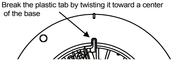
- To remove the detector from the base once the locking feature has been activated, insert a small screwdriver into the slot on the base to push the plastic tab while simultaneously turning the detector head counter-clockwise (refer to Figure 2).
Figure 2. Removing of detector head from base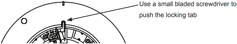
- To remove the base cover from the lower enclosure once the locking feature has been activated, insert a small screwdriver into the slot on the on the base to push the plastic tab while simultaneously turning the detector head counter-clockwise (refer to Figure 3).
Figure 3. Removing of base cover from the lower enclosure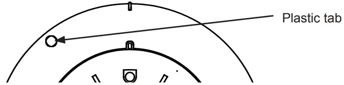
Specifications
| No. | Item | ASB-6 | |
| 1 | Working voltage range for SLC | 22.0 to 24.0 V | |
| 2 | Standby current for SLC 1 | 325 pA | |
| 3 | Working voltage range for 24V | 19.0 to 28.0 V | |
| 4 | Active current for 24V | 100 mA D.C. | |
| 5 | Sound pressure level | 85dB/3m (min.) as per CAN/ULC-S525 75dB/10ft (min.) as per UL464 | |
| 6 | Installation temperature range | 32°F to 120°F (0°C to 49°C ) | |
| 7 | Operating relative humidity range | 0% to 93% (Non-condensing) | |
| 8 | Start-up time | Max. 1 sec. | |
| 9 | Maximum number of addresses per zone | 127 | |
| 10 | Color | Eggshell White | |
| 11 | Dimensions (without detector) | Height | 2.13 inches (54.4mm) |
| Diameter | 6 inches (150mm) | ||
| (1)The standby current is the current that the device consumes when the device is in a non-activated condition and where no communication current is transmitted to the fire alarm control panel. (2)FHA with ASB should be installed under 120°F. (Installation temperature range of ASB is 32°F to 120°F.) | |||
MKT. #8830011 – REV C
firealarmresources.com
PRINTED IN USA


