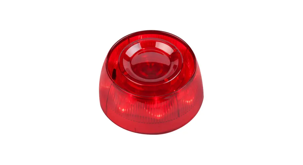
![]() SensoIRIS WSOU-xx Intelligent Analogue Addressable Fire Alarm Sounder
SensoIRIS WSOU-xx Intelligent Analogue Addressable Fire Alarm Sounder
Instruction Manual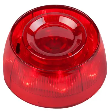
SensoIRIS WSOU-xx Intelligent Analogue Addressable Fire Alarm Sounder
![]()
DoP No: 007
Tested by EVPU
Teletek Electronics JSC
Address: 14A Srebarna Str,
1407 Sofia, Bulgaria
EN 54-3:2001
EN 54-3:2001/A1:2002
EN 54-3:2001/A2:2006
Sounder Type: B
| Essential characteristics | Performance |
| Performance under fire conditions | Pass |
| Operational reliability | Pass |
| Durability: | |
| Temperature resistance | Pass |
| Humidity resistance | Pass |
| Shock and vibration resistance | Pass |
| Corrosion resistance | Pass |
| Resistance to ingress | Pass |
| Electrical stability | Pass |
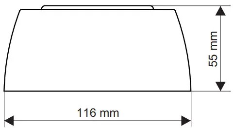
![]() Dimensions
Dimensions
Installation Instruction
ATTENTION: Read carefully this installation Instructions before installing the device! This manual is subject to change without notice!
SensoIRIS WSOU is n addressable Wall Mount Sounder а designed for installing in addressable fire alarm systems supporting TTE communication protocol. The device is powered on from the panel and can be controlled via the communication protocol.
The sounder SensoIRIS OU is compatible with fire bases WSB124 for ceiling or wall mounting and WSB IP65 for wall mounting (refer to manual 18020861 for details).
Installation Instructions
Attention: Power off the loop circuit before installing the SensoIRIS WSOU addressable sounder!
- Choose the proper place for installation of the device.
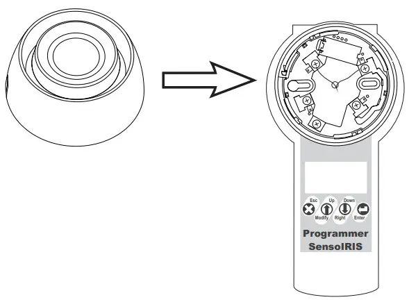
- Set the device address using SensoIRIS Programmer or directly from addressable fire panel. The address must be in the range from 1 to 250.
- Mount the fire base on the ceiling or on the wall of the protected premises using fixings according the mounting surface.
- Connect the base to the fire panel using the wiring diagram.
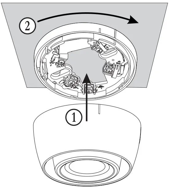
- Insert the device into the base and rotate clockwise until it drops into place – the short mark on the base fits with that on the sounder body. Continue to rotate the sounder until its mark coincides with the long mark on the base – a click is heard.
- Program the device parameters. Choose in consecutiveness from the control panel: System – Programming – Devices – Loop. Find the installed sounder, as enter address, loop and zone number – the panel automatically will recognize the type of the device. Choose the button MORE to enter in the additional settings menu.
- Test the sounder for proper operation.
Warranty
All devices carry on a warranty valid from the date of manufacture. The date of manufacture can be checked by the code marking on the back of the device. The date is printed numbers – YY MM. The first two numbers represent the year and the last two – the month. For example: The date code “20 07”, means the device is manufactured in July, 2020.
To return goods for warranty service, please contact with your local distributer for details.
Technical Specifications
| Operating Voltage Range | 15 – 32VDC (Nom. 27VDC) |
| Nominal consumption (stand-by) | <500μА@27VDC |
| Maximal consumption (main tone type 27): | |
| – low volume level | <5mА |
| – high volume level | <16.5mА |
| Maximal consumption (other tone types): | |
| – low volume level | <4mА |
| – high volume level | <10mА |
| Power volume (main tone type 27): | |
| – low volume | ~ 80dB (A) ± 6dB @ 1m |
| – high volume | ~ 92dB (A) ± 5dB @ 1m |
| Power volume (other tone types): | |
| – low volume | 75-85dB ± 3dB @ 1m |
| – high volume | 80-95dB ± 3dB @ 1m |
| Number of tone types | 32 |
| Supported communication protocol | ТТЕ |
| Wire Gauge for terminals | 2.5mm |
| Relative humidity resistance | (93 ± 3)% @ 40°C |
| Color (according the model): | |
| – WSOU-R | red |
| – WSOU-WT | white |
| – WSOU-AT | amber |
| – WSOU-RT | red |
| Material: | |
| – WSOU-R | ABS |
| – WSOU-WT (transparent) | SAN |
| – WSOU-AT (transparent) | SAN |
| – WSOU-RT (transparent) | SAN |
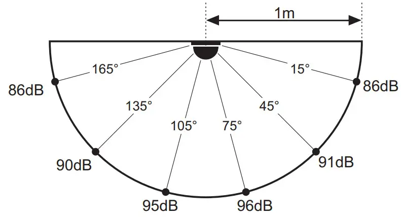
![]() A-weighted sound level diagram
A-weighted sound level diagram
 Installation
| IP43C (ЕN 54-3)* IP65 (EN 60529)** | |
| -10°C ÷ +50°C | |
| ~183g | |
| Indoor use* | |
| Outdoor use** |
* When used with base B124
** When used with base WSB IP65 (Tested by EVPU)
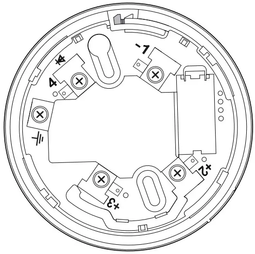
- Base B124

- Address programming
 Note: You may also program the address directly from the fire panel.
 - Mounting Base B124

- Mounting the sounder

 Note: You may also program the address directly from the fire panel.
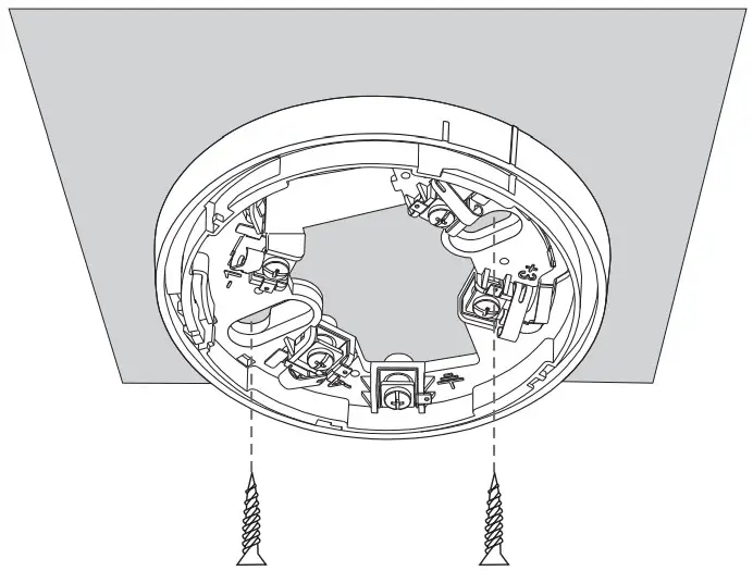
Wiring Diagram
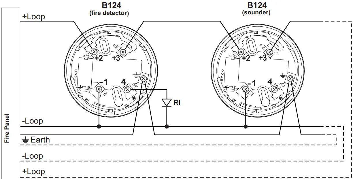
Legend
RI – Remote Indicator
+Loop – Positive loop wire
-Loop – Negative loop wire
Earth – Earth point
 Tone types and description
| Tone | Tone Type | Tone Description / Application |
| 1 | 970Hz | |
| 2 | 800Hz/970Hz @ 2Hz | |
| 3 | 800Hz – 970Hz @ 1Hz | |
| 4 | 970Hz 1s OFF/1s ON | |
| 5 | 970Hz, 0.5s/ 630Hz, 0.5s | |
| 6 | 554Hz, 0.1s/ 440Hz, 0.4s (AFNOR NF S 32 001) | |
| 7 | 500 – 1200Hz, 3.5s/ 0.5s OFF (NEN 2575:2000) | |
| 8 | 420Hz 0.625s ON/0.625s OFF (Australia AS1670 Alert tone) | |
| 9 | 500 – 1200Hz, 0.5s/ 0.5s OFF x 3/1.5s OFF (AS1670 Evacuation) | |
| 10 | 550Hz/440Hz @ 0.5Hz | |
| 11 | 970Hz, 0.5s ON/0.5s OFF x 3/ 1.5s OFF (ISO 8201) | |
| 12 | 2850Hz, 0.5s ON/0.5s OFF x 3/1.5s OFF (ISO 8201) | |
| 13 | 1200Hz – 500Hz @ 1Hz (DIN 33 404) | |
| 14 | 400Hz | |
| 15 | 550Hz, 0.7s/1000Hz, 0.33s | |
| 16 | 1500Hz – 2700Hz @ 3Hz | |
| 17 | 750Hz | |
| 18 | 2400Hz | |
| 19 | 660Hz | |
| 20 | 660Hz 1.8s ON/1.8s OFF | |
| 21 | 660Hz 0.15s ON/0.15s OFF | |
| 22 | 510Hz, 0.25s/ 610Hz, 0.25s | |
| 23 | 800/1000Hz 0.5s each (1Hz) | |
| 24 | 250Hz – 1200Hz @ 12Hz | |
| 25 | 500Hz – 1200Hz @ 0.33Hz | |
| 26 | 2400Hz – 2900Hz @ 9Hz | |
| 27 | 2400Hz – 2900Hz @ 3Hz (2500Hz – main sound frequency) | |
| 28 | 800Hz – 970Hz @ 100Hz | |
| 29 | 800Hz – 970Hz @ 9Hz | |
| 30 | 800Hz – 970Hz @ 3Hz | |
| 31 | 800Hz, 0.25s ON/1s OFF | |
| 32 | 600Hz – 1100Hz, 2.6s/0.4s OFF |
![]() 18020193
18020193
RevC; 01/2022


