 H-1224 SERIES
INDOOR/OUTDOOR
SELECT-A-HORN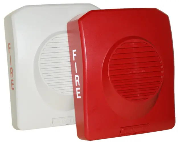
![]()
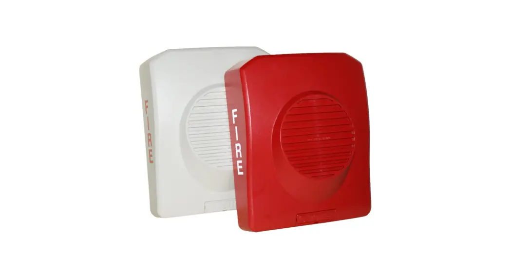
H-1224 Series Electronic Horn Fire Alarm
- UL and cUL listed
- 33 sound output settings
- Horn or chime sound output
- Indoor/outdoor* listed
- Pre-wire back plate
- Universal back plate mounting (single gang, double gang, octagon, or 4” square)
- Single screw mounting
- Low current draw * Outdoor installation requires the BBK-1 #1500001, BBX-5R
#4270048, or BBX-5W #4270049
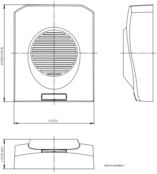
The back plate allows the installer to mount the plate and terminate the wire connections. The horn attaches in a hinge fashion from the top and is secured by a single mounting screw. The horn completely covers the mounting back plate, therefore it can be mounted before other trades work is completed and not affect the final look.
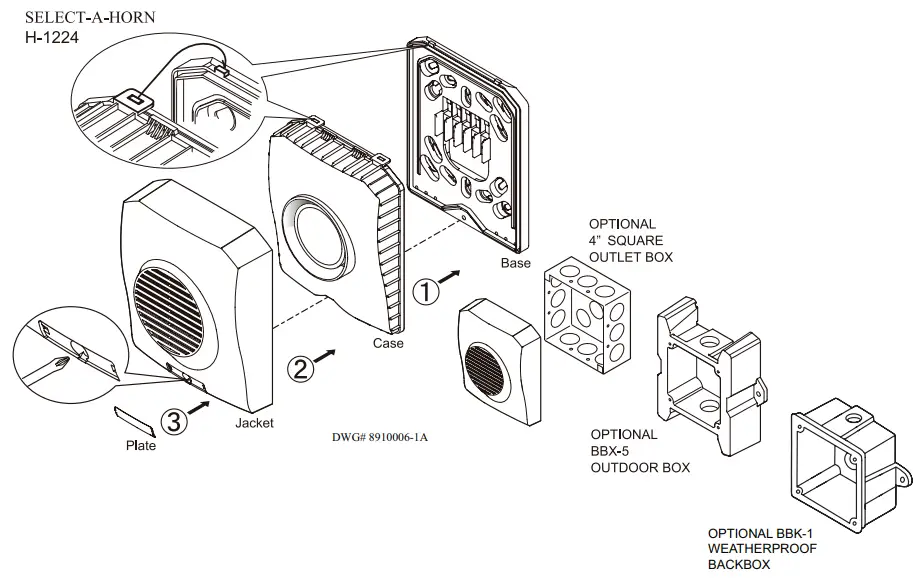
Installation
Note: Installation must comply in accordance with applicable standards.
![]() CAUTION
CAUTION
A jumper plug is provided to test for correct wiring in the supervisory mode only. Do not pass alarm current through the jumper.
Ordering Information
| Stock Number | Model Number | Description | Color |
| 4560050 | H-1224R | Selectable horn | Red |
| 4560051 | H-1224W | Selectable horn | White |
Non-Temporal Horn Current
| Pattern | Volume | Max. RMS Current (mA RMS Current) | dBA Reverberant Ratings per UL464 (dBA @ 10 ft.) | dBA Anechcic Ratings per CAN/ULC 5525 (dBA @ 10 ft.) | |||
| Reg 12 VDC | Reg 24 VDC | Reg 12 VDC | Reg 24 VDC | Reg 12 VDC | Reg 24 VDC | ||
| 2400 Hz | High | 119 | 87 | 87 | 87 | 99 | 100 |
| Mid | 44 | 28 | 82 | 82 | 94 | 96 | |
| Low | 30 | 18 | 79 | 80 | 92 | 92 | |
| Electro-Mechanical | High | 118 | 81 | 86 | 87 | 100 | 100 |
| Mid | 43 | 26 | 82 | 84 | 96 | ||
| Low | 27 | 16 | 79 | 80 | 93 | 93 | |
| Broadband | High | 146 | 78 | 86 | 86 | 101 | 102 |
| Mid | 41 | 26 | 81 | 82 | 96 | 98 | |
| Low | 28 | 16 | 77 | 79 | 94 | 95 | |
| Chime | High | 27 | 71 | 70 | 70 | 86 | 86 |
| Mid | 11 | 8 | 62 | 62 | 79 | 80 | |
| Low | 9 | 7 | 58 | 57 | 75 | 75 | |
Temporal Horn Current
| Pattern | V olume | Max. RMS Current (mA RMS Current) | dBA Reverberant Ratings per UL464 (dBA @ 10 ft.) | dBA Anechcic Ratings per CAN/ULC 5525 (dBA ® 10 ft.) | |||
| Reg 12 VDC | Reg 24 VDC | Reg 12 VDC | Reg 24 VDC | Reg 12 VDC | Reg 24 VDC | ||
| 2400 Hz | High | 124 | 87 | 82 | 82 | 100 | 100 |
| Mid | 46 | 30 | 77 | 79 | 95 | 96 | |
| Low | 30 | 18 | 74 | 75 | 92 | 92 | |
| Electro-Mechanical | High | 114 | 80 | 83 | 82 | 100 | 101 |
| Mid | 42 | 27 | 78 | 80 | 95 | 96 | |
| Low | 28 | 16 | 75 | 76 | 93 | 93 | |
| Broadband | High | 151 | 80 | 82 | 82 | 101 | 102 |
| Mid | 45 | 26 | 77 | 78 | 97 | 98 | |
| Low | 30 | 16 | 75 | 76 | 94 | 95 | |
| Chime | High | 29 | 21 | 68 | 70 | 86 | 86 |
| Mid | 10 | 9 | 61 | 61 | 79 | 79 | |
| Low | 9 | 8 | 55 | 55 | 75 | 76 | |
March Time Horn Current
| Patter. | Volume | Max. RMS Current (mA RMS Current) | dBA Reverberant Ratings per UL464 (dBA @ 10 ft.) | dBA Anecho’c Ratings per CAN/ULC S52 (dBA @ 10 ft.) | |||
| Reg 12 VDC | Reg 24 VDC | Reg 12 VDC | Reg 24 VDC | Reg 12 VDC | Reg 24 VDC | ||
| 2400 Hz | High | 121 | 92 | 83 | 84 | 99 | 100 |
| Mid | 47 | 31 | 79 | 81 | 95 | 96 | |
| Low | 36 | 19 | 76 | 77 | 92 | 92 | |
| Electro-Mechanical | High | 114 | 86 | 83 | 83 | 100 | 100 |
| Mid | 42 | 27 | 80 | 81 | 95 | 96 | |
| Low | 30 | 19 | 77 | 77 | 92 | 93 | |
| Broadband | High | 153 | 77 | 83 | 84 | 101 | 102 |
| Mid | 42 | 28 | 79 | 80 | 97 | 98 | |
| Low | 29 | 16 | 76 | 77 | 94 | 95 | |
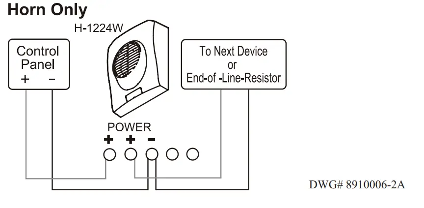
Wiring Diagram
Wiring Observe Polarity Use both terminals (or Lead) for connection. Break wire run to provide electrical supervision.
Dimensions: inches (mm)
Dipswitch Settings
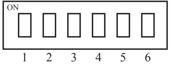 Pattern
1 ON – Non-temporal
1 OFF – Temporal
Both 2 = OFF
1 and 2 ON = March Time
Tone
3 and 4 ON = 2400Hz
3 ON and 4 OFF = Electromagnetically
3 and 4 OFF = Chime
3 OFF and 4 ON = Broadband
Volume
5 and 6 ON = High
5 ON and 6 OFF = Mid
5 and 6 OFF = Low
| Voltage | 12/24V | |
| UL Designation | Regulated 12 DC/ FWR | Regulated 24 DC/FWR |
| Operating Voltage Range | 8 – 17.5V | 16 – 33V |
| Sync Modules | NA | Available |
| Operating Temperature Range | Indoor: 32°F to 120°F (0°C to 49°C) Outdoor: -40°F to 151°F (-40°C to 66°C) | |
Engineering Specifications
The installer shall provide and install the Potter H-1224 indoor/ outdoor selectable horn. The horn shall have thirty-three (33) different settings. The horn shall be selectable for continuous (non-temporal), temporal (ANSI Code 3) and March Time patterns. The horns shall have a 2400 hertz, Electro-Mechanical, Broadband or a Chime tone.
Each of the patterns and tones shall be selectable for a Low, Mid or High volume setting. The horn shall operate at 12 or 24 VDC regulated or full wave rectified. The horn shall have an operating range between 8 and 33 VDC. The horn shall utilize a mounting plate that allows the installer to pre-wire the mounting plate. The mounting plate shall be universal and mount on a single gang, double gang, octagon or 4 inch square box. If the horn is needed in a wet or outdoor installation, it shall be mounted on either a BBK-1 4” square back box or a BBX-5 outdoor matching back box. The horn shall have a gasket on the back plate that seals the electrical connection of the terminal connection. The mounting plate shall be completely covered by the horn and shall be secured by a single screw. Operating temperature range will be 32°F to 120°F (0°C to 49°C) for indoor model and -40°F to 151°F (-40°C to 66°C) for outdoor model. The horn shall be UL listed to standard 464, Audible Signaling Devices. In addition, the device shall be cUL listed to CAN-ULC S525.
PRINTED IN USA
MKT. #8910006 – REV E 7/10
Potter Electric Signal Co., LLC • St. Louis, MO
Cust Service: 866-240-1870 • Tech Support:866-956-1211
Canada 888-882-1833
www.pottersignal.com
firealarmresources.com


