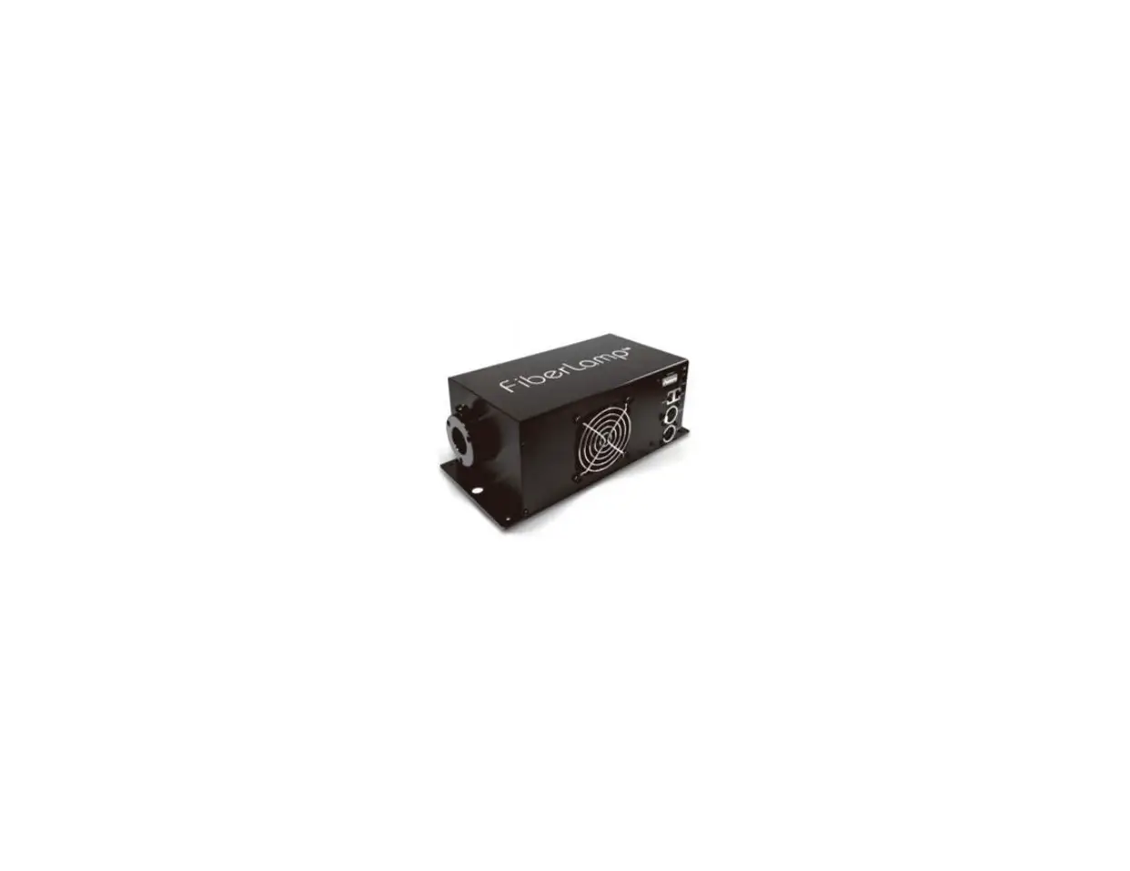
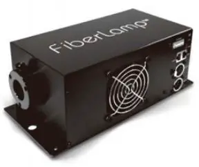
FiberLamp FL5200 LED Fiber Optic Illuminator
Contents
- FL5200
- IEC 60320 C13 to NEMA 5-15 AC Power Cable
Fiber Installation Precautions
When using stranded fiber, make certain that no fibers come into contact with the twinkle effect wheel. Contact over time can cause accelerated failure of the twinkle effect wheel motor.
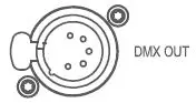
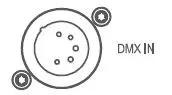
Connector and Switch Diagram
| Connectors Function | |
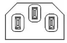 | IEC 60320 C14 Plug for AC Input |
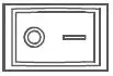 | Power Switch |
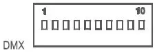 | DIP-Switch for DMX Addressing |
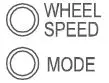 | Pushbuttons for Manual Control (2) |
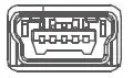 | Mini-USB Service Port (Manufacturer use) |
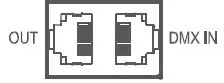 | RJ45 Connectors for DMX (2) |
 | Female XLR5 Connector for DMX |
 | Male XLR5 Connector for DMX |
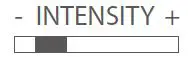 | Intensity Bar |
Color
| Mode Color Dimmable | ||
| 0 | Blank | N/A |
| 1 | 5000K ( 1 CH ) | Yes |
| 2 | Red | Yes |
| 3 | Green | Yes |
| 4 | Blue | Yes |
| 5 | Yellow | Yes |
| 6 | Cyan | Yes |
| 7 | Magenta | Yes |
| 8 | Rainbow | No |
| 9 | 3000K ( Mixed ) | No |
| 10 | 4200K ( Mixed ) | No |
| 11 | 5000K ( Mixed ) | No |
Twinkle Wheel
| Mode | 1 | 2 | 3 | 4 | 5 |
| Setting | Slow | Slow-Med | Medium | Med-Fast | Fast |
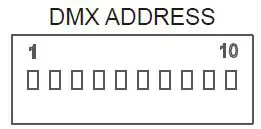
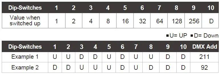
Set DMX Address
The DMX address is set by binary dip switches.
DMX Channels
| DMX Control Channels Color | |
| 1 | 5000K |
| 2 | Red |
| 3 | Green |
| 4 | Blue |
| 5 | Magenta |
| 6 | Master Light Intensity |
| 7 | Twinkle Wheel |
| 8 | Strobe Control |
| Notes Twinkle Wheel: 0-1 Wheel stopped, 2-125 clockwise rotation slow to fast, 126-131 Wheel stopped, 132-255 Counterclockwise rotation fast to slow. Strobe Control: 0-1 No blinking, 2-255 Blink rate slow to fast. | |
DMX Pin-outs for RJ45 connector
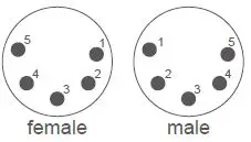
| RJ45 XLR5 Function | ||
| 1 | 3 | Data (+) |
| 2 | 2 | Data (-) |
| 3 | 5 | Not Assigned |
| 4 | – | Internal Use Only |
| 5 | – | Internal Use Only |
| 6 | 4 | Not Assigned |
| 7 | 1 | DMX Ground |
| 8 | 1 | DMX Ground |
0-10V Dimming Pin-outs for RJ45 connector
| RJ45 Typical Cat-5e Wire Color Function | ||
| 1 | Orange/White | NA |
| 2 | Orange | NA |
| 3 | Green/White | 10V Source |
| 4 | Blue | 0-10V Sink |
| 5 | Blue/White | NA |
| 6 | Green | NA |
| 7 | Brown/White | Reference |
| 8 | Brown | Reference |
To set the FL5200 in 0-10V dimming mode, set the DMX Address DIP-switch pin #10 to the up position.
- Current sink – Connect the variable feed of the controller to both pins 3 and 4. Connect the reference feed of the controller to pins 7 and 8.
- Current source – Connect the variable feed of the controller to pin 4 only.
Connect the reference feed of the controller to pins 7 and 8.
510.620.5155


