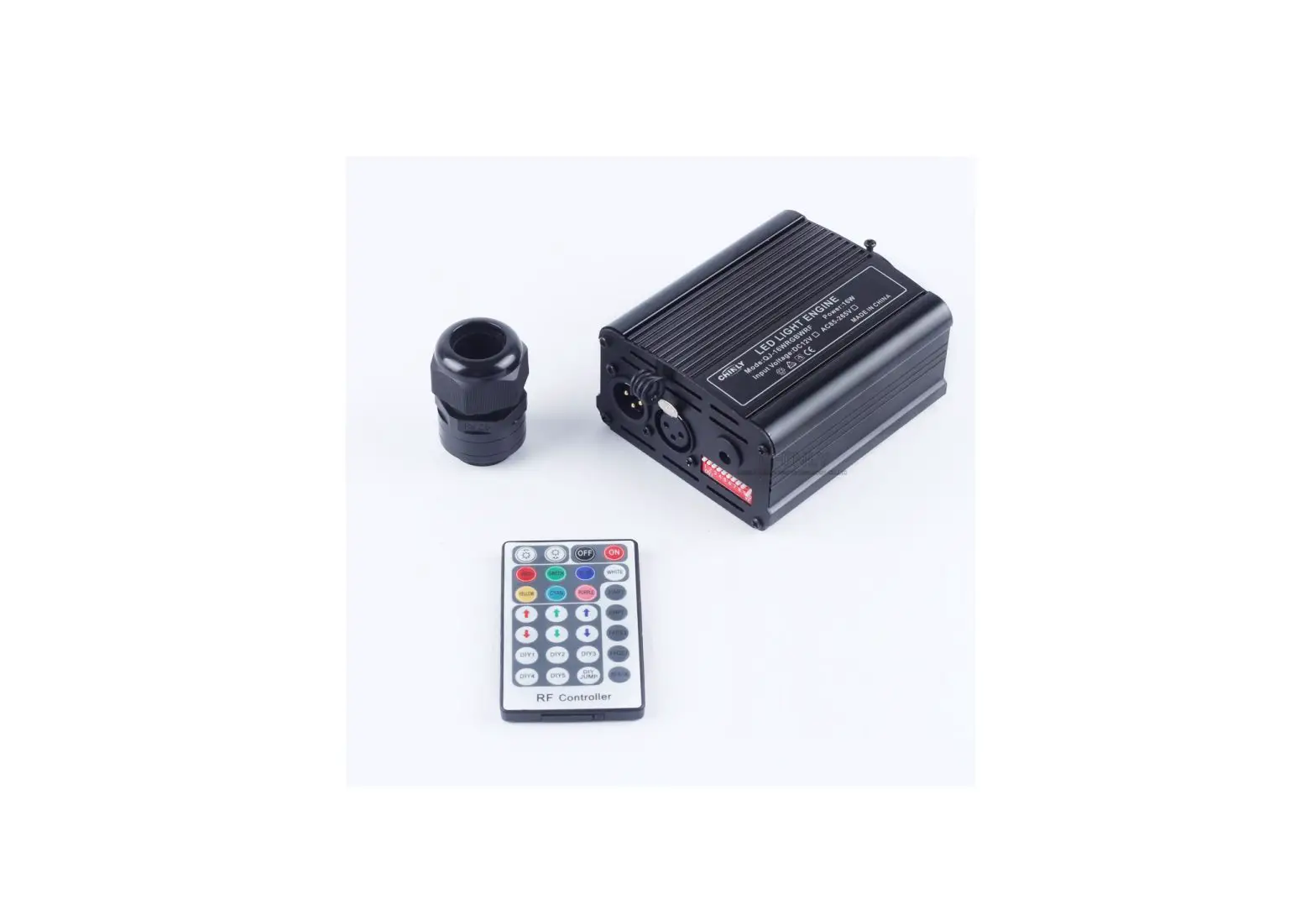
LED LIGHTING HUT QJ-FB16RGBWRFDMX 16W RGBW DMX Fiber Optics Light User Manual
Technical Specification
- Input voltage:AC86-265V
- POWER: 16W
- COLOR: RGBW
- LED:RGBW LED
- Output gray level: 256
- Input Signal: DMX512/1990
- Output DMX : 4 channels( RGBW) DMX512 socket standard XLR;
- Net Weight: 535g Gross Weight: 605g
- Light source device size:L115*W95*H55mm
- Fiber head inner diameter:16-20mm
- Light body material: Aluminum
- Remote: RF
- Remoter dimension: L85× W52 × H7mm
- Package Size:L220*W127*H65mm
- Lifetime: 50,000 hours
- Warranty: 2 years
MODE1:DMX MODE
Note: FUN = OFF (the tenth code switch up) means to accept DMX512 signal mode
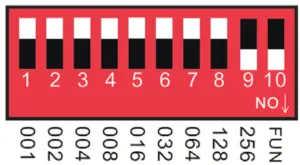
The first DMX address setting:
The decoder set the address bit by coding switch, of which 1-9 is for setting the start address of the Binary numeric code switch of DMX512, the first one is the lowest position, the ninth one is the highest Bit of address code can be set to 512.
DMX512 start address code is the sum of switches 1-9, at the same time turn downside of the code switch (ON set to “1”), then the value of the bit can be gotten; coding switch up (set to “0”), the value of the bit is 0.
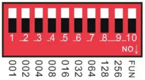
- Example 1:
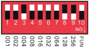
As the following Schematic 1, DMX512 start address is set to 38, encoding the No. 6,3,2 position on switch dial to “1”, others set to “0”, then the sum of the switch 1-9 code value is 32 + 4 + 2, that is the DMX512 start address 38
Schematic 1
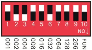
- Example 2:
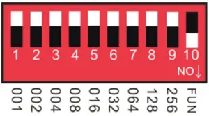
As the schematic 2, DMX512 start address is set to 388, encoding the no. 2,3,6,8 switch dial to “1”, others set to “0”, then the sum of the switch 1-8 code value is 4 + 128 + 256 = 388, that is the DMX512 start address 388.
Schematic 2
MODE2:RF MODE
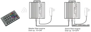
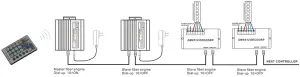
Note: It will be rf mode when the No. 10 switch is turned down.
Remote instructions: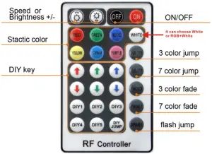
Match Code Function (It is available when leave factory)
- Power on led engine, it works well when red indicated lights.
- Press the FADE3 and FADE7 at same time in the effective remote distance, the white color of led engine flash. The code matches success.
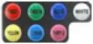
RF28 key remote control function
Key function details specification

ON/OFF Turn ON/OFF the controller 
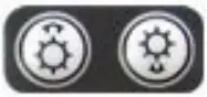
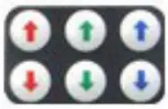
Speed/brightness
adjust keyPress this two keys to increase/decrease the brightness when in static mode
Press these two keys to increase/decrease the changing speed when in dynamic modestatic color mode brightness is adjustable 
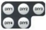
DIY brightness adjust key Press the DIY key to address the Green, Red, Blue color brightness to choose the specific color
DIY mode key Press the key to save the DIY color
you adjust be the DIY brightness adjust key
DIY JUMP Press the key to realize all the color setting by DIY to JUMP

3 color JUMP Red, Green, Blue color jump 
7 color JUMP Red, Green, Blue, Yellow, cyan, purple white color jump
color fade Red, Green, Blue color fade 7 color fade Red, Green, Blue, Yellow, purple, cyan, white color fade
SPARK Dynamic mode 7 color flash Jump white mode white, RGB+ white change


MODE3:Built-in effects Mode
Effect choice (button switch No.1 to No.4):12 kinds
- Push No.1: Seven-color gradual cycle changing.
- Push No. 2: RGB Fade in and out
- Push No.1 &2: Severn color jumping
- Push No.3: RGB jumping.
- Push No.1 & 3: RGB flash jumping.
- Push No.2 & 3: Static red
- Push No. 1 & 2 & 3:Static green
- Push No.4: Static blue
- Push No.1 & 4: Static yellow
- Push No.2 & 4: Static purple
- Push No.1 & 2 & 3: Static cyan
- Push No.3 & 4: Static white
Speed Choices (Button Switch No.5 to No. 7) 8 kinds
- Push No.5: 0.5 second.
- Push No.6: 1 second.
- Push No.5,6: 1.5 second.
- Push No.7: 2 second.
- Push No.5: 0.5 second.
- Push No.6: 1 second.
- Push No.5,6: 1.5 second.
- Push No.7: 2 second.
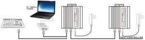
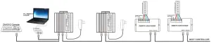
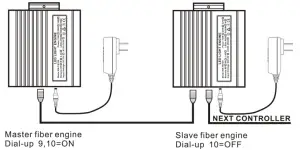
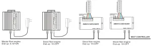
Application Connection Diagram
- DMX MODEL


- RF MODEL


- BUILT_IN MODEL


Maximum fiber connection formula
Fiber head’s radius: R
Fiber Diameter: D1,D2,D3……….
Fiber quantity:N1,N2,N3……
Result:Π*R*R>=N1*D1*D1+N2*D2*D2+N3*D3*D3…………….
Example:
fiber head’s radius (Diameter 20mm)
Fiber Diameter:0.75mm,1.0mm,1.5mm
Fiber Quantity:150mm,50mm,10mm……
Result:3.14*10*10>=150*0.75*0.75+50*1*1+10*1.5*1.5
fiber head inner diameter :16-20MM
The number of optical fiber can be installed:
| model | PG Connector inner diameter(MM) | fiber diameter(MM) | max fiber number |
| QJ-FB16RGBWRFDMX | 16-20 | 0.75 | 450 |
| QJ-FB16RGBWRFDMX | 16-20 | 1 | 250 |
| QJ-FB16RGBWRFDMX | 16-20 | 1.5 | 100 |
| QJ-FB16RGBWRFDMX | 16-20 | 2 | 60 |
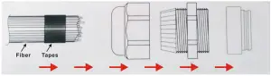
Connection method between Fiber and Led engine
- Align all the fiber head, fasten with tapes which can resistance temperature over 130℃
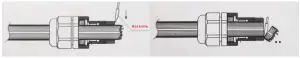
- Pass through the fiber to connector, fastening rotary tensioner. To make sure the fiber bunch could not move and each fiber must be in the same plane.

- Cut the fiber bunch to flat surface by heat-knife or blade.

- Make sure the fiber bunch head is smooth and clean. Thus each fiber’s light will be evenly.
- Put through the whole fiber connector to fix ring of Led engine. Fasten screw on the top of the fix ring.
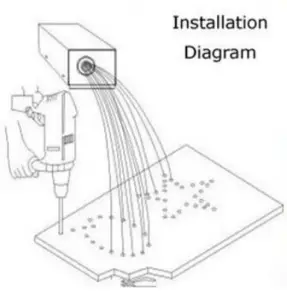
Application installation diagram
Attention:
- Make sure the input voltage is correct.
- Put led engine in the rain or moist place is prohibited
- Please don’t open led engine for inspection or change the electronic circuits if you are not professionor.
- Led engine has to be good ventilation, please don’t put at sealed place.
- Put debris on top of led engine or around it will be caused poor heat dissipation.


