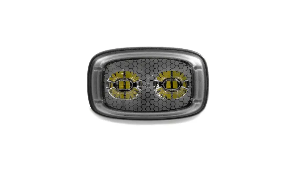
cell2 Reactor LED Warning Modules
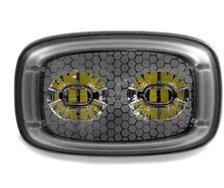
WARNING LIGHTHEAD
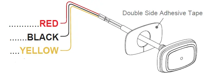
Wiring
To+VDC for Warning Mode (fuse @ 1A):……………RED
To Chassis Ground:…………………………………BLACK
For Synchronization and Flash Pattern:……..YELLOW
Connect YELLOW wires of all lightheads together for synchronization. (All lightheads should be set to the same flash pattern)
For Simultaneous or Alternating Flash:
Each Warning Mode may select and save one Flash Pattern. While activating a Warning Mode, momentarily apply YELLOW wire to +VDC:
- Once to the next pattern.
- Quick three times to the default Flash Pattern (FP#1).
For Simultaneous or Alternating Synchronization:
| FP# | Flash Patterns | |
| 1 | Double | [2Hz] |
| 2 | Single | [2Hz] |
| 3 | Triple | [2Hz] |
| 4 | Quad | [2Hz] |
| 5 | Random | |
| 6 | Steady EF* | |
| 7 | Single | [SAE/CA13] |
| 8 | Double | [SAE] |
| 9 | Triple | [SAE] |
| 10 | Quad | [SAE] |
| 11 | Quint | [SAE] |
| 12 | Mega | |
| 13 | Giga | |
| 14 | Ultra | [SAE] |
| 15 | Single-Quad | |
| 16 | Single H/L | |
| 17 | Single-Triple-Quint | |
| 18 | Steady Scene | |
- Apply +VDC to RED and YELLOW wires simultaneously to enter SETTING MODE; the lighthead will display short flashes:
- Single flash = Group 1
- Double flash = Group 2
- Remove YELLOW wire from +VDC then momentarily apply to +VDC to change Groups.
- Lightheads of the same Group will flash together.
- Lightheads of the different Group will flash alternately.
Reset to Factory Default Settings:
- Apply +VDC to RED and YELLOW wires simultaneously to enter SETTING MODE;
- Remove YELLOW wire from +VDC then momentarily apply to +VDC again for more than 5 seconds. The lighthead will display fast short flashes to signify restoring successfully.
- Save and exit SETTING MODE by disconnecting all power.
Installation
- Drill a 15mm wire passage hole on the mounting surface. Make sure no vehicle parts could be damaged by the drilling process. (Thoroughly deburr hole and use grommet for wire passage hole if needed)
- Clean and dry the mounting surface with 50:50 mix of isopropyl alcohol and water.
- Remove the tape liner from the tape.
- Apply the tape onto the mounting surface.
- Align and apply the lighthead with tape and press it firmly for 30 seconds.
- Full adhesion and bonding will be achieved after 72 hours at room temperature.


