![]()
![]() bks+6-FIU Ultrasonic Web Edge Sensor with
bks+6-FIU Ultrasonic Web Edge Sensor with
Analogue Output And IO-Link Interface
Instruction Manual
Product Description
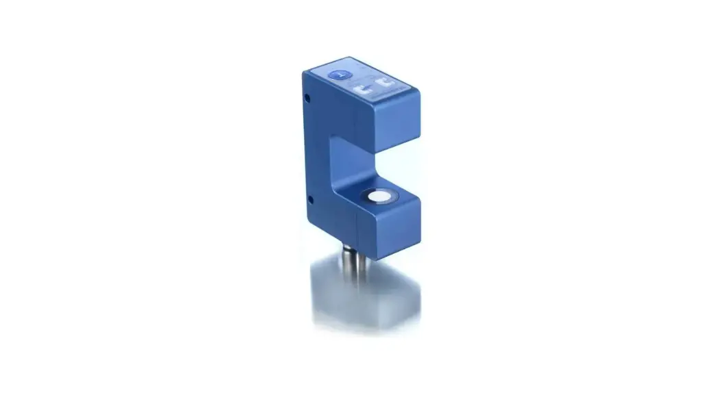
The bks+ ultrasonic web edge sensor is a fork sensor for scanning the edges of sound-impermeable and slightly sound-permeable materials such as foil or paper. The fork’s lower leg is equipped with an ultrasonic sensor which cyclically emits short sound impulses, which are detected by the ultrasonic receiver accommodated in the upper fork leg. Material immersing into the fork covers this sound path and thus attenuates the receive signal, which is evaluated by the internal electronics. An analogue signal and a binary value via IO-Link is output in dependence of the coverage degree. The bks+6/FIU optional can be programmed using the LinkControl-Adapter LCA-2 and LinkControl software.
- Via the Teach-in button on the edge sensor’s top or via Pin 5 on the device plug, the sensor can be adjusted to the material to be controlled.
- Choosing between rising and falling output characteristic is possible.
- Three LEDs indicate the position of the web material inside the fork.
Safety Notes
- Read the operating manual prior to start-up.
- Connection, installation and adjustment works may only be carried out by expert personnel.
- No safety component in accordance with the EU Machine Directive.
IO-Link
The bks+6/FIU sensors are IO-Link-capable in accordance with IO-Link specification V1.1.
Installation
- Mount the sensor at the installation site.
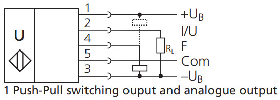
- Connect a connection cable to the M12 device plug, see Fig. 1.
Start-Up
- Connect the power supply.
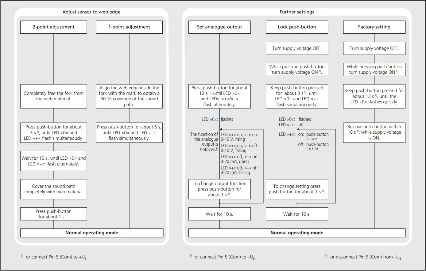
- Carry out the adjustment to the web material in accordance with Diagram 1.
| colour | ||
| 1 | +UB | brown |
| 3 | –UB | blue |
| 4 | black | |
| 2 | I/U | white |
| 5 | Com | grey |
Fig. 1: Pin assignment with view onto sensor plug and colour coding of the microsonic connection cable
Synchronization
If two or more edge sensors are mounted in a distance <50 mm the internal synchronization should be used. Connect Sync-channels (Pin 5 at the units receptacle) of all sensors.
Factory setting
- Analogue output on voltage output
- Rising analogue characteristic (0 V at maximum coverage)
- Switching output on NOC
- Switching output window is ±4.5 mm around zero position.
Maintenance
microsonic sensors are maintenancefree. With heavy dirt deposits, we recommend a cleaning of the white sensor surface.
Diagram 1: Sensor adjustment via Teach-in procedure
Technical data
 | 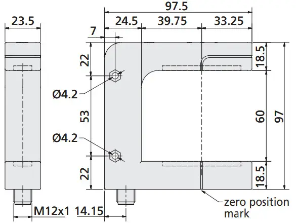 |
| fork width | 60 mm |
| fork depth | 73 mm |
| working range | ≥40 mm (±20 mm) |
| transducer frequency | ca. 310 kHz |
| resolution | 0.01 mm |
| reproducibility | ±0.1 mm |
| operating voltage UB | 20 to 30 V DC, reverse polarity protection |
| voltage ripple | ±10 % |
| no-load current consumption | ≤60 mA |
| housing | zinc die cast chromed, plastic parts: PBT ultrasonic transducer: polyurethane foam, epoxy resin with glass contents |
| class of protection to EN 60 529 | IP 65 |
| type of connection | 5-pin M12 initiator plug, brass, nickel-plated |
| controls | Teach-in-button and Teach-in via pin 5 |
| indicators | LED green: centre or within switching window LEDs yellow: outside the centre/switching window |
| programmable | LCA-2 with LinkControl and IO-Link |
| synchronisation | internal synchronisation up to 10 sensors |
| operating temperature | +5 to +60 °C |
| storage temperature | –40 to +85 °C |
| weight | 280 g |
| response time | 6 ms |
| measurement cycle time | 4 ms |
| time delay before availability | < 300 ms |
| order no. | bks+6/FIU |
| analogue output | current output 4 to 20 mA voltage output 0 to 10 V short-circuit-proof, switchable rising/falling |
| switching output | Push-Pull, UB –3 V, –UB +3 V, Imax = 100 mA switchable NOC/NCC; short-circuit-proof |
Notes
- Working range and gradient of the analogue output curve depend on the ultrasonic transducers and cannot be adjusted. The working range always is ≥40 mm.
- For sound-impermeable materials the sensor can be adjusted to the environmental conditions by the 1-point adjustment procedure.
- For slightly sound-permeable materials the sensor has to be set up to the material and the environmental conditions by using the 2-point adjustment. Carry out a practical test to find out whether a material is slightly sound-permeable.
- For optimum measurement results the material to be detected should be kept in a range of ±5 mm around the centre between the upper and lower fork leg.
- The sensor can be reset to its factory settings (see »Further settings«, Diagram 1).
- Using the LinkControl-Adapter LCA-2 (optional accessory) and the LinkControl-Software V7.6 additional sensor parameters can be adjusted and Teach-in procedures can be carried out.
- Depending on the function the ultrasonic transducers in the upper and lower fork leg are mounted with a slope of 2°.
IO-Link Mode
The bks+6/FIU sensors are IO-Link-capable in accordance with IO-Link specification V1.1 and compatible to specification V1.0.
Note
In IO-Link mode Teach-in and Link- Control are not available.
Process data
The bks+ cyclically transmits the value corresponding to the measured coverage degree with a resolution of 0.01 mm.
Service data
The following sensor parameters may be set via IO-Link.
Teach-in via push-button
The push-button can be activated/ deactivated for sensor settings with Teach-in.
Temperature compensation
The temperature compensation is used for measurement value correction for varying ambient temperatures and can be disabled.
Analogue output mode
For the analogue output either voltage or current output can be selected.
Rising/falling analogue characteristic
The analogue characteristic can be set on rising (0 V/4 mA at full coverage) or falling characteristic.
Set NOC/NCC
The NCC or NOC output function can be preset for the switching output.
Switching off the LEDs
When activated, the LEDs are turned off 30 seconds after a key press. After a new key press they will run for 30 seconds. This automatic shutdown can be deactivated.
IO-Link Data
| physical layer | bks+6/FIU |
| IO-Link revision | V1.1 |
| compatibilty | V1.0 |
| block parameter | yes |
| data storage | yes |
| SIO mode support | yes |
| min cycle time | 4 ms |
| baud rate | COM 2 |
| format of process data | 16 Bit, R, UNI16 |
| content of process data | Bit 0-15: degree of coverage with 0.01 mm resolution |
| service data IO-Link specific | index | access | value | |
| vendor name | 0x10 | R | microsonic GmbH | |
| vendor text | 0x11 | R | www.microsonic.de | |
| product name | 0x12 | R | bks+ | |
| product ID | 0x13 | R | bks+6/FIU | |
| product text | 0x14 | R | Ultraschall-Sensor |
| service data sensor specific | index | format | access | range | default |
| Teach-in via push-button | 0x40 | UINT8 | R/W | 0: activated; 1: deactivated | 0 |
| temperature compensation | 0x42 | UINT8 | R/W | 0: deactivated; 1: activated | 1 |
| analogue output mode | 0x44 | UINT8 | R/W | 2: current output, 3: voltage output | 3 |
| rising/falling output characteristic curve | 0x45 | UINT8 | R/W | 0: rising characteristic curve; 1: falling characteristic curve | 0 |
| NCC/NOC | 0x46 | UINT8 | R/W | 0: NOC; 1: NCC | 0 |
| automatic turning-off LEDs | 0x48 | UINT8 | R/W | 0: deactivated; 1: activated | 1 |
| measurement filter | 0x4D | UINT8 | R/W | 0-2: F00-F02 | 0 |
| filter strength | 0x4E | UINT8 | R/W | 0-9: P00-P09 | 0 |
| centre of switching window | 0x4F | INT16 | R/W | 0-4095 1) | 2047 |
| width of switching window | 0x50 | UINT16 | R/W | 0-4095 1) | 1023 |
| system commands | index | access | value | |
| restore IO-Link parameter | 0x02 | W | 130 | |
| sensor adjustment: fork cleared | 0x02 | W | 161 | |
| sensor adjustment: fork 50 % covered | 0x02 | W | 162 | |
| sensor adjustment: fork 100 % covered | 0x02 | W | 163 | |
| reset to factory setting | 0x02 | W | 164 |
| events | code | type | name |
| 0x8ca0 | Notification | parameter was changed | |
| 0x8ca1 | Notification | sensor adjustment successful | |
| 0x8ca2 | Notification | sensor adjustment failed |
| observe | index | format | access | range |
| measurement value | 0x54 | UINT16 | R | 0-4095 1) |
1) The value range 0-4,095 corresponds with the working range of the sensor.
Measurement filter
bks+ ultrasonic sensors provide for a choice of 3 filter settings:
- F00 (no filter)
Each ultrasonic measurement acts on the output in an unfiltered manner. - F01 (average value filter)
Forms approximately the arithmetic mean of several measurements. According to the mean value the output is set. The number of measurements, from which the mean is formed is dependent on the chosen filter strength. - F02 (median filter)
Finds the median of several measurements. According to the median the output is set. The number of measurements, for which the median is determined is dependent on the selected filter strength.
Filter strength
For both measurement value filters, a filter strength between P00 (weak filter effect) and P09 (strong filter effect) can be selected.
Switching window
If the web edge is within the switching window the switching output is set. The switching window is defined by the adjusted centre and the width.
Note
The switching window has to be within the operating range.
System commands
With 5 system commands the following settings may be carried out:
- restore IO-Link parameters to their factory settings (system command 130)
- sensor adjustment: fork cleared.
- sensor adjustment: fork 50 % covered
- sensor adjustment: fork 100 % covered
- reset all sensor parameters including the IO-Link parameters to their factory settings (system command 164)
Events
The bks+ sensor sends the following events:
- parameter was changed
- sensor adjustment successful
- sensor adjustment failed
IODD file
The latest IODD file you will find on the internet under www.microsonic.de/en/IODD.
For further informations on IO-Link see www.io-link.com.
The content of this document is subject to technical changes. Specifications in this document are presented in a descriptive way only. They do not warrant any product features.
![]()
 2014/30/EU
microsonic GmbH
Phoenixseestraße 7
44263 Dortmund
Germany
T +49 231 975151-0
F +49 231 975151-51
E [email protected]
W microsonic.de


