![]()
Installation Manual
US01B.M8 / US04B.M8
Ultrasonic sensor for web guiding systems
Document Version 1.80 Issue Date / Author 02/2017 / NS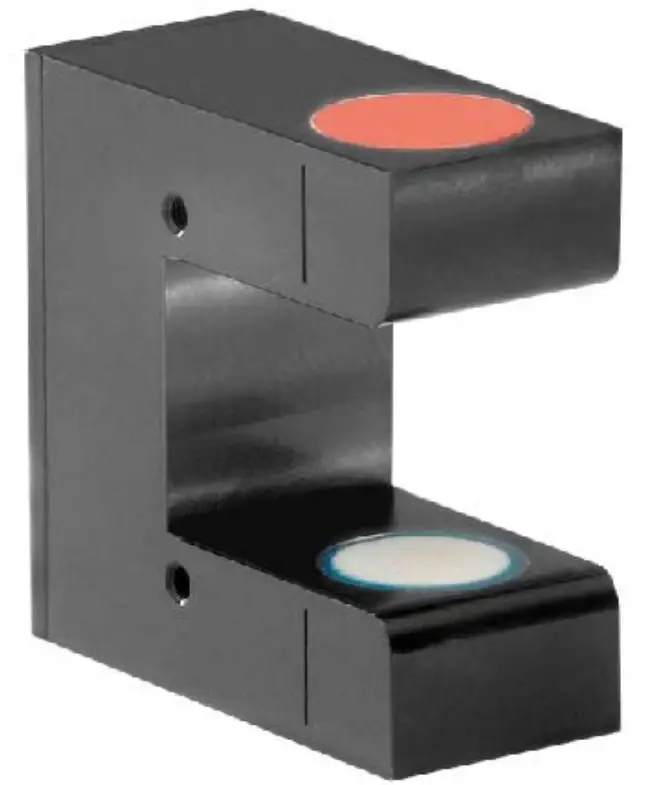
Safety instructions
All safety-related regulations, local codes, and instructions that appear in the manual or on equipment must be observed to ensure personal safety and to prevent damage to
the equipment connected to it. If equipment is used in a manner not specified by the manufacturer, the protection provided by the equipment may be impaired. Do not stress the equipment over the specification limits neither during assembly nor operation. To do so can be potentially harmful to persons or equipment in the event of a fault to the equipment.
2.1 Presentation of safety information
The following safety symbols appear in this manual.
2.1.1 Danger that could result in minor or moderate injuries![]() Danger, warning, caution
Danger, warning, caution![]() Failure to follow wiring instructions in this manual may result in equipment damage or personal injury.
Failure to follow wiring instructions in this manual may result in equipment damage or personal injury.
2.1.2 Note regarding the proper function![]() Note
Note
Note regarding proper operation Simplification of operation Ensuring function
General safety information
![]() The Material Sensors may not be stressed over the specification limits either during assembly or operation.
The Material Sensors may not be stressed over the specification limits either during assembly or operation.![]() The attachment points for the Sensors on the machine frame must be properly designed. The used mounting screws must be of the right size.
The attachment points for the Sensors on the machine frame must be properly designed. The used mounting screws must be of the right size.
Product information
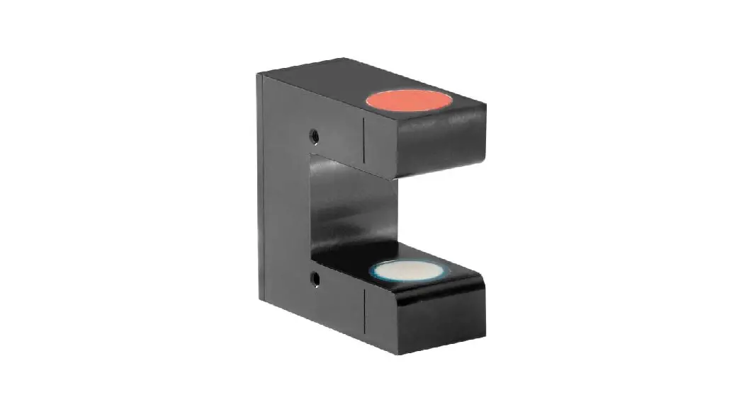
3.1 System description
The ultrasonic sensors can detect a very wide range of web materials including transparent films. The sensors are not suitable for sound permeable materials (e.g. netlike or open weave textiles). They are factory set and don’t need any adjustments or calibration. The main advantage of these sensors is the save detection of transparent films of all sizes. The sensor is almost insensitive to changes of material planarity or dust thanks to an optimized sensor and micro-processor controlled ultra-sound transmission.
3.2 Dimensions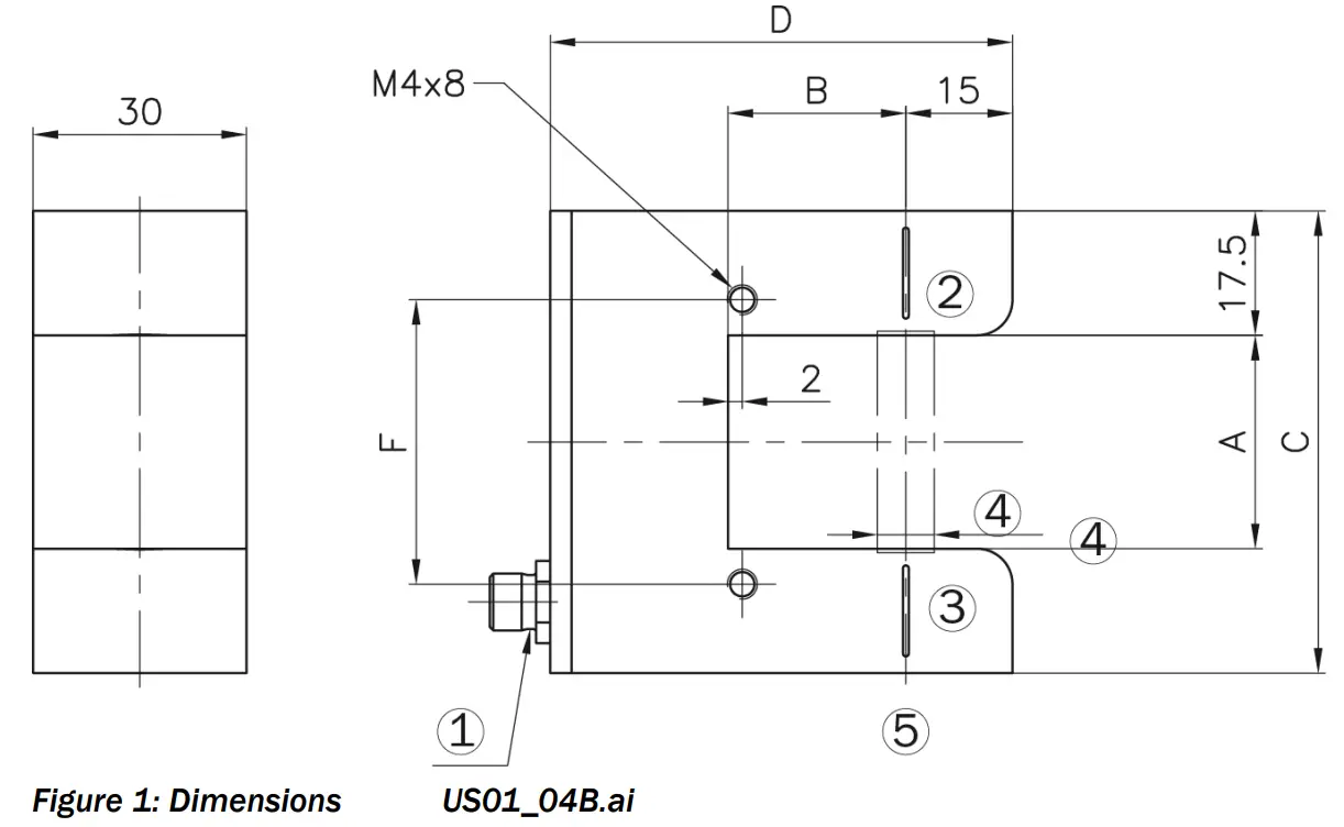
| Dimensions mm (In.) | |||
| USO1B.M8 | USO4B.M8 | ||
| (A)Fork width | 30 (1.18) | 90 (3.54) | |
| (B)Fork depth | 25 (0.89) | 80 (3.15) | |
| (C)Sensor hight | 65 (2.56) | 125 (4.92) | |
| (D)Sensor length | 65 (2.56) | 120 (4.92) | |
| (F) Bore distance | 40 (1.57) | 100 (4.92) | |
| (4) Detection range | 8 (0.31) | 8 (0.31) | |
Table 1: Dimensions
| Terms | |
| Position | Description |
| 1 | LED in plug |
| 2 | Marking of the center of the sensor detection area |
| 3 | Marking of the center of the sensor detection area |
| 5 | Side of the ultrasonic transmitter |
Table 2: Terms
Scope of delivery
3.3.1 Included
material sensor, installation manual
3.3.2 Not included
screws, washers, mounting bracket, cable
3.3 Scope of delivery
Installation
4.1 Preparation
The sensors are defined as “partly completed machinery” according to the Directives 2006/42/EC, Article
2. In order to assure proper functionality of the parts and guarantee the essential health and safety requirements of operators working with it, the following conditions for the assembly must be met:
4.2 General safety information![]() The Material Sensors may not be stressed over the specification limits either during assembly or operation.
The Material Sensors may not be stressed over the specification limits either during assembly or operation.![]() The attachment points for the Sensors on the machine frame must be properly designed. The used mounting screws must be of the right size.
The attachment points for the Sensors on the machine frame must be properly designed. The used mounting screws must be of the right size.![]() For correct installation and operation, follow the electrical wiring diagram and instructions in this manual.
For correct installation and operation, follow the electrical wiring diagram and instructions in this manual.
4.3 Electrical connections
The sensor will be mounted with two M4 screws to a bracket. The bracket itself is fixed to the location rail or to the flange of the steering frame or linear actuator. The bracket varies depending on system configuration (steering frame size, manual or motorized sensor adjustment, etc.). It is not part of the supply and must be ordered separately. If the sensor is used with an integrated web guide controller within an FMS steering frame FMS-webMASTER, the sensor is connected with a cable 4×0.14mm2 of the respective length.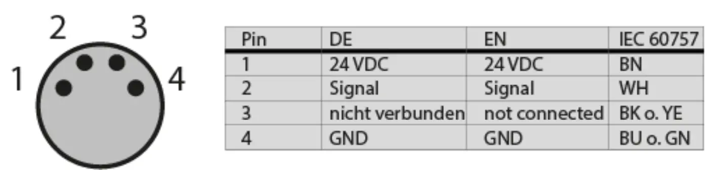
Figure 2: Pin assignment Pin_Assignment_Sensorkabel_Farben_Stecker.ai
Operation
5.1 Denomination of the sensor position
Left and right are always seen in direction of the running web.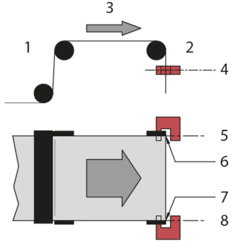 Figure 3: Terms on steering frames BKS_309.ai
| Terms | |
| Position | Description |
| 1 | Entry side |
| 2 | Exit side |
| 3 | Rolling direction |
| 4 | Sensor axis |
| 5 | Sensor axis left |
| 6 | Web edge left |
| 7 | Sensor axis right |
| 8 | Web edge right |
Table 3: terms sensor position
5.2 Alignment of the sensor 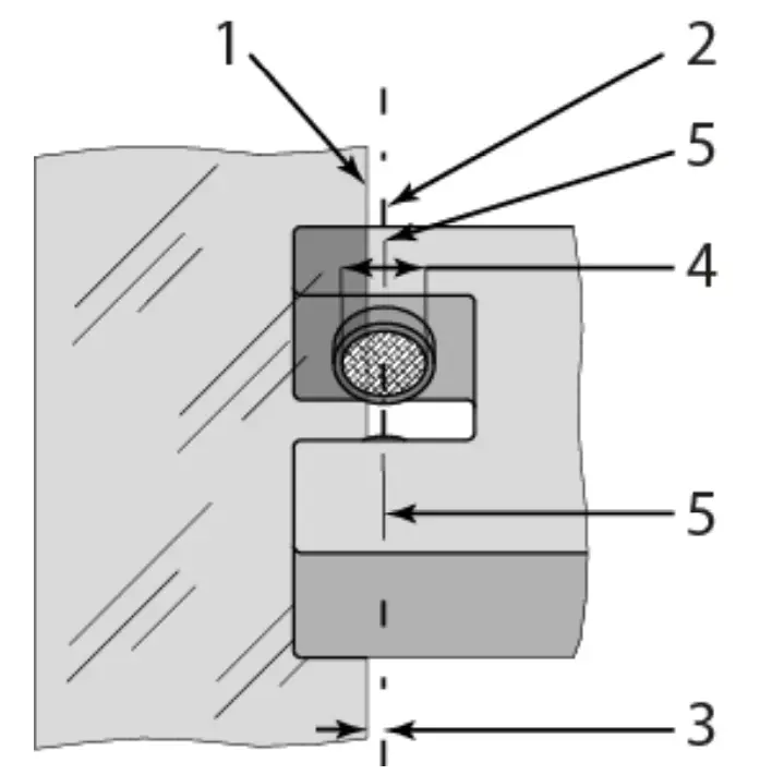
Figure 4: Alignment of the sensor
| Terms sensor alignment | |
| Position | Description |
| 1 | Web edge |
| 2 | Sensor axis |
| 3 | Deviation of web edge to the sensor axis |
| 4 | Detection range of the sensor |
| 5 | Marking for mid of detection area |
Table 4: Sensor alignment
– Loosen the fixing nut on the bracket and adjust the sensor.
– The positioning marks provide a quick and precise alignment of the sensor to the reference edge.
– Fix the sensor in the new position.
– The sensor will be properly positioned if the web edge goes through the sensor axis covering half of the ultrasonic transmitter or receiver (ref. to Fig. 4).
Troubleshooting
Causes and possible solutions for errors
| Description of error | Cause | Corrective action |
| Limited control range | Edge has moved outside the sensor detection range | Adjust the sensor more accurately to the center of the measuring range. |
| Occasional control dropouts | Ultrasonic transmitter or receiver side is dirty | Clean sensor with a wet cloth |
| BKS guides web edge immediately out of the sensor detection area | The sensor is installed on the wrong side | Install sensor on the correct side (right sensor for,, Edge right”, etc. |
| Sensor is connected to the wrong socket | Connect sensor plug to the correct socket (left plug to the left socket, etc.) | |
| The steering frame does not move at all | No signal; sensor not connected correctly | Connect sensor correctly according to screw terminal arrangement, follow the installation manual of web guide controller |
| No signal; cable interruption | Replace the cable or send the sensor to FMS | |
| No signal; sensor defect | Send sensor to FMS; use another sensor | |
| No power supply | Check 24VDC supply | |
| The sensor signal is OV. The sensor is fully covered | Adjust sensor more accurately to the web edge; center measuring range | |
| The sensor signal is 10V. The sensor is uncovered | Adjust sensor more accurately to the web edge; center measuring range |
Table 5: errors and solutions
Technical data
| Technical data | ||
| Parameter | USO1B.M8 / USO4B.M8 | |
| Detection range | 8 mm [0.31″] | |
| Resolution | 0.2 mm [0.007″] | |
| Measuring rate | 2 ms | |
| Output signal | 0 to 10 VDC OV if detection area is fully covered 10V if detection area is not covered at all 5V if the material edge is centered in the detection area, LED is active | |
| Power supply | 24 VDC (18 to 30 VDC) | |
| Connecting cable | M8 connector 4-pole | |
| Temperature range | 0 to 60 C [32 to 140 F] | |
| Protection class | IP 67 | |
Table 6: Technical data
![]()
| FMS Force Measuring Systems AG Aspstrasse 6 8154 Oberglatt (Switzerland) Tel. 0041 1 852 80 80 Fax 0041 1 850 60 06 [email protected] www.fms-technology.com | FMS USA, Inc. 2155 Stonington Avenue Suite 119 Hoffman Estates,, IL 60169 (USA) Tel. +1 847 519 4400 Fax +1 847 519 4401 [email protected] | FMS (UK) Highfield, Atch Lench Road Church Lench Evesham WR11 4UG (Great Britain) Tel. 01386 871023 Fax 01386 871021 [email protected] | FMS Italy Via Baranzate 67 20026 Novate Milanese Phone +39 02 39487035 Fax +39 02 39487035 [email protected] |


