![]()
![]()
Operating manual
Ultrasonic proximity switch with one switching output and IO-Link
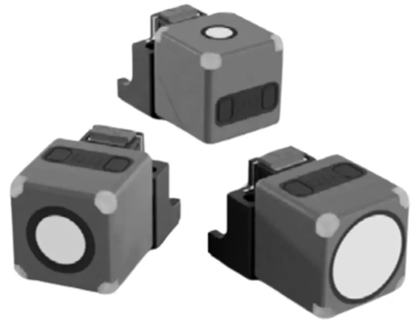
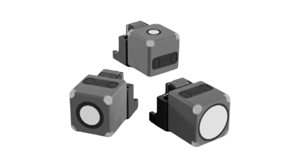
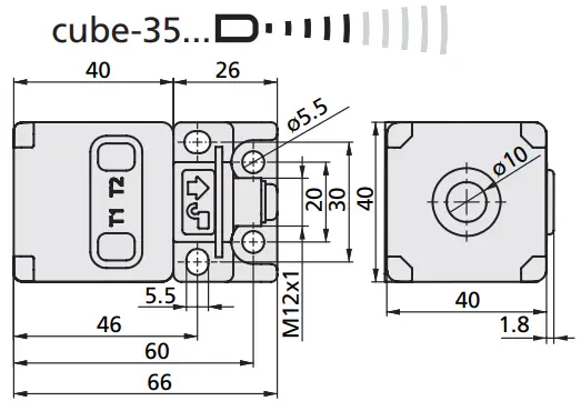
cube-35/F
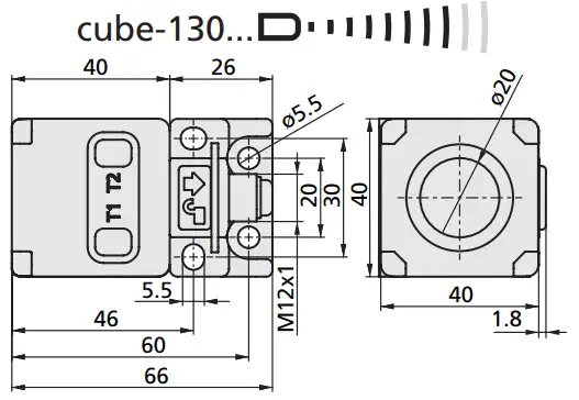
cube-130/F
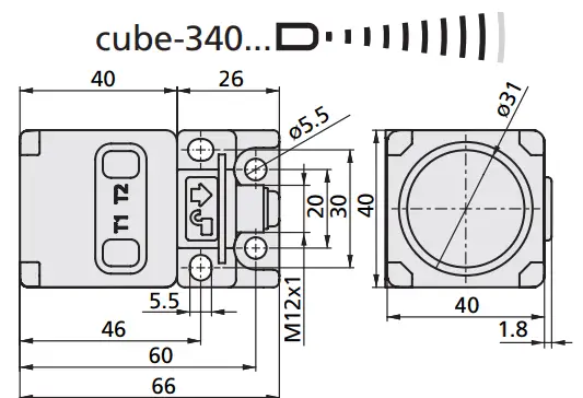
cube-340/F
Product Description
The cube sensor offers a non-contact measurement of the distance to an object which must be positioned within the sensor’s detection zone.
The switching output is set conditional upon the adjusted switching distance.
Safety Notes
- Read the operating manual prior to start-up.
- Connection, installation and adjustments may only be carried out by qualified staff.
- No safety component in accordance with the EU Machine Directive, use in the area of personal and machine protection not permitted.
Proper Use
cube ultrasonic sensors are used for non-contact detection of objects.
IO-Link
The cube sensor is IO-Link-capable in accordance with IO-Link specification V1.1 and supports Smart Sensor Profile like Measuring and Switching Sensor. The sensor can be monitored and parameterised via IO-Link.
Installation
![]() Mount the sensor at the place of fitting, see »QuickLock mounting bracket«.
Mount the sensor at the place of fitting, see »QuickLock mounting bracket«.![]() Connect a connection cable to the M12 device plug, see Fig. 2.
Connect a connection cable to the M12 device plug, see Fig. 2.![]() If necessary, use the alignment assistance (see »Using the Alignment Assistance«).
If necessary, use the alignment assistance (see »Using the Alignment Assistance«).
Start-up
![]() Connect the power supply.
Connect the power supply.![]() Set the parameters of the sensor, see Diagram 1.
Set the parameters of the sensor, see Diagram 1.
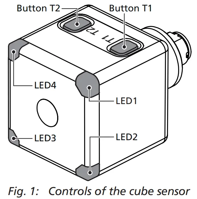
Controls of the cube sensor
The sensor can be operated using the push buttons T1 and T2. Four LEDs indicate the operation and the state of the output, see Fig. 1 and Fig. 3.
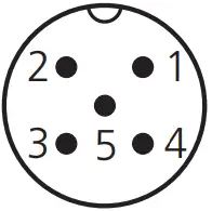 | microsonic notation | IO-Link notation | IO-Link Smart Sensor Profile | colour |
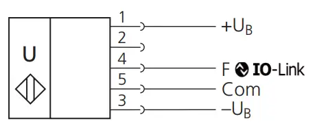
| 1 | +UB | L+ | brown | |
| 2 | – | – | – | white |
| 3 | –UB | L– | blue | |
| 4 | F | Q | SSC | black |
| 5 | Com | NC | grey |
Fig. 2: Pin assignment with view onto sensor plug, IO-Link notation and colour coding of the microsonic connection cables
| LED | Colour | Indicator | LED… | Meaning |
| LED1 | yellow | state of output | on off | output is set output is not set |
| LED2 | green | power indicator | on flashing | normal operating mode IO-Link mode |
| LED3 | green | power indicator | on flashing | normal operating mode IO-Link mode |
| LED4 | yellow | state of output | on off | output is set output is not set |
Fig. 3: Description of the LED indicators
Diagram 1: Set sensor via Teach-in procedure
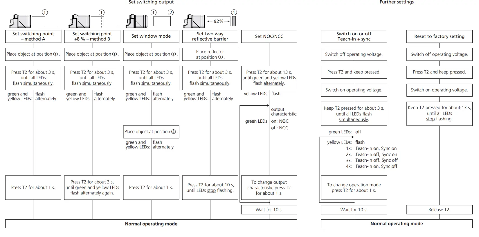
Operating Modes
- Operation with one switching point
The switching output is set when the object falls below the set switching point. - Window mode
The switching output is set when the object is within the window limits. - Two-way reflective barrier
The switching output is set when the object is between sensor and fixed reflector.
Synchronisation
If the assembly distance of multiple sensors falls below the values shown in Fig. 4, they can influence one another.
To avoid this, the internal synchronisation should be used (»sync« must be switched on, see Diagram 1). Interconnect each pin 5 of the sensors to be synchronised.
| cube-35… cube-130… cube-340… | ≥0.40 m ≥1.10 m ≥2.00 m | ≥2.50 m ≥8.00 m ≥18.00 m |
Fig. 4: Minimal assembly distances without synchronisation
QuickLock mounting bracket
The cube sensor is attached using the QuickLock mounting bracket:![]() Insert the sensor into the bracket according to Fig. 5 and press until the bracket audibly engages.
Insert the sensor into the bracket according to Fig. 5 and press until the bracket audibly engages.
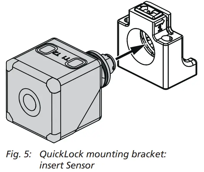
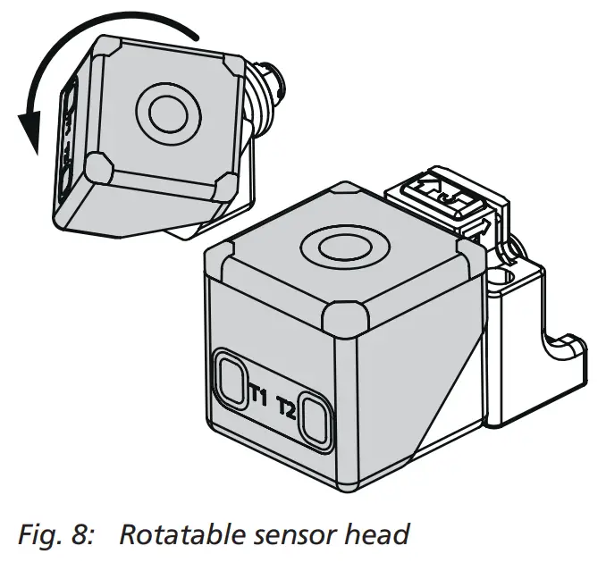
The sensor can be rotated around its own axis when inserted into the bracket. Furthermore, the sensor head can be rotated so that measurements can be taken in four different directions, see »Rotatable sensor head«.
The bracket can be locked:![]() Slide the latch (Fig. 6) in the direction of the sensor.
Slide the latch (Fig. 6) in the direction of the sensor.
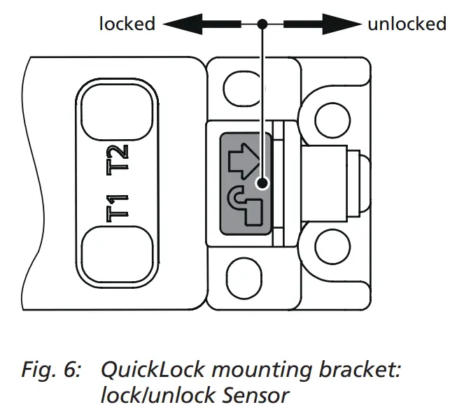
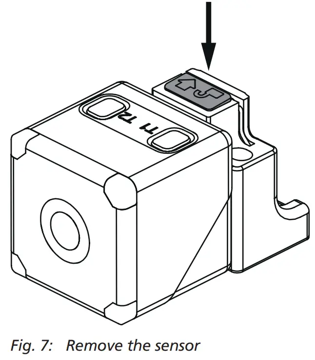
Remove the sensor from the QuickLock mounting bracket:![]() Unlock the latch according to Fig. 6 and press down (Fig. 7). The sensor detaches and can be removed.
Unlock the latch according to Fig. 6 and press down (Fig. 7). The sensor detaches and can be removed.
Rotatable sensor head
The cube sensor has a rotatable sensor head, with which the orientation of the sensor can be rotated by 180° (Fig. 8).
Factory Setting
The cube sensor is delivered factory made with the following settings:
- Switching output on operating mode switching point
- Switching output on NOC
- Switching distance at operating range
- Input Com set to »sync«
- Filter at F01
- Filter strength at P00
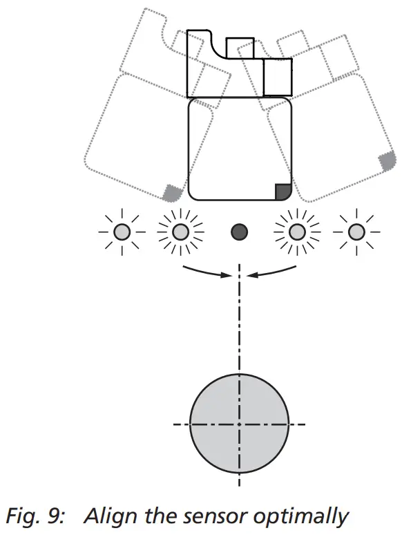
Using the Alignment Assistance
With the internal alignment assistance the sensor can be optimally aligned to the object during installation. To do this, proceed as follows (see Fig. 9):![]() Mount the sensor loosely at the place of mounting so that it can still be moved.
Mount the sensor loosely at the place of mounting so that it can still be moved.![]() Press T2 shortly. The yellow LEDs flash. The faster the the yellow LEDsflash, the stronger the received signal.
Press T2 shortly. The yellow LEDs flash. The faster the the yellow LEDsflash, the stronger the received signal.![]() Point the sensor at different angles to the object for about 10 seconds so that the sensor can determine the maximum signal level. Afterwards align the sensor until the yellow LEDs light constantly.
Point the sensor at different angles to the object for about 10 seconds so that the sensor can determine the maximum signal level. Afterwards align the sensor until the yellow LEDs light constantly.![]() Screw the sensor in this position.
Screw the sensor in this position.![]() Press T2 shortly (or wait approx. 120 s) to exit the Alignment Assistance. The green LEDs flash 2x and the sensor returns to normal operating mode.
Press T2 shortly (or wait approx. 120 s) to exit the Alignment Assistance. The green LEDs flash 2x and the sensor returns to normal operating mode.
Maintenance
microsonic sensors are maintenancefree. In case of excess caked-on dirt we recommend cleaning the white sensor surface.
Notes
- The cube sensor has a blind zone, within which a distance measurement is not possible.
- The cube sensor is equipped with an internal temperature compensation. Due to the sensors self heating, the temperature compensation reaches its optimal working point after approx. 3 minutes of operation.
- The cube sensor has a push-pull switching output.
- Choosing between output function NOC and NCC is possible.
- In the normal operating mode the illuminated yellow LEDs signal that the switching output is set.
- The flashing green LEDs indicate that the sensor is in IO-Link mode.
- If a Teach-in procedure is not completed, all changes are deleted after approx. 30 seconds.
- If all LEDs flash rapidly alternately for approx. 3 seconds during a teach-in procedure, the teach-in procedure was not successful and is discarded.
- In the »Two-way reflective barrier« operating mode, the object has to be within the range of 0 to 92 % of the set distance.
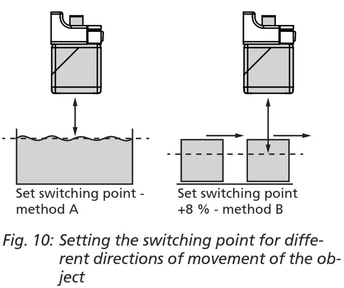
- In the »Set switching point – method A« Teach-in procedure the actual distance to the object is taught to the sensor as the switching point. If the object moves towards the sensor (e.g. with level control) then the taught distance is the level at which the sensor has to switch the output.
- If the object to be scanned moves into the detection area from the side, the »Set switching point +8 % – method B« Teach-in procedure should be used. In this way the switching distance is set 8 % further than the actual measured distance to the object. This ensures a reliable switching behavior even if the height of the objects varies slightly, see Fig. 10.
- The sensor can be reset to its factory setting (see »Further settings«, Diagram 1).
- The cube sensor can be locked against unwanted changes in the sensor via function »Switch on or off Teach-in + sync«, see Diagram 1.
- Using the LinkControl adapter (optional accessory) and the LinkControl software for Windows®, all Teach-in and additional sensor parameter settings can be optionally adjusted.
- The latest IODD file and informations about start-up and configuration of cube sensors via IO-Link, you will find online at: www.microsonic.de/en/cube.
Scope of delivery
- 1x QuickLock mounting bracket
Technical data
 |  |  |  |
| blind zone | 0 to 65 mm | 0 to 200 mm | 0 to 350 mm |
| operating range | 350 mm | 1,300 mm | 3,400 mm |
| maximum range | 600 mm | 2,000 mm | 5,000 mm |
| angle of beam spread | see detection zone | see detection zone | see detection zone |
| transducer frequency | 400 kHz | 200 kHz | 120 kHz |
| measurement resolution | 0.056 mm | 0.224 mm | 0.224 mm |
| digital resolution | 0.1 mm | 1.0 mm | 1.0 mm |
| detection zones for different objects: The dark grey areas represent the zone where it is easy to recognise the normal reflector (round bar). This indicates the typical operating range of the sensors. The light grey areas represent the zone where a very large reflector – for instance a plate – can still be recognised. The requirement here is for an optimum alignment to the sensor. It is not possible to evaluate ultrasonic reflections outside this area. | 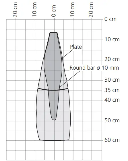 | 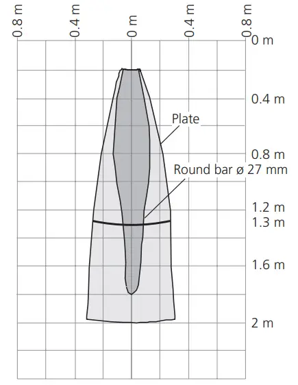 | 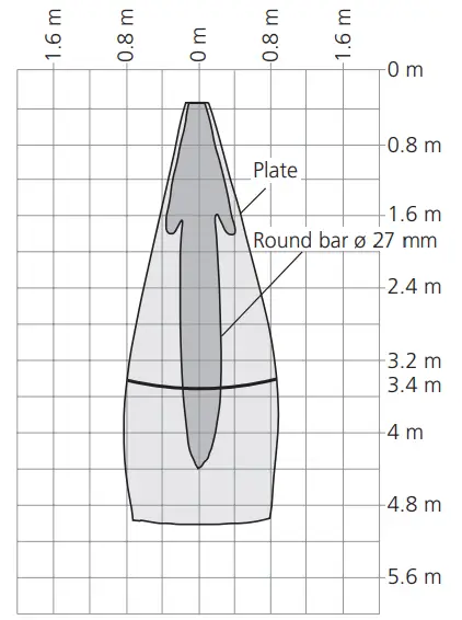 |
| reproducibility | ±0.15 % | ±0.15 % | ±0.15 % |
| accuracy | ±1 % (Temperature drift internal compensated, may be deactivated 1) , 0.17%/K without compensation) | ±1 % (Temperature drift internal compensated, may be deactivated 1) , 0.17%/K without compensation) | ±1 % (Temperature drift internal compensated, may be deactivated 1) , 0.17%/K without compensation) |
| operating voltage UB | 9 to 30 V DC, reverse polarity protection (Class 2) | 9 to 30 V DC, reverse polarity protection (Class 2) | 9 to 30 V DC, reverse polarity protection (Class 2) |
| voltage ripple | ±10 % | ±10 % | ±10 % |
| no-load supply current | ≤50 mA | ≤50 mA | ≤50 mA |
| housing | PA, Ultrasonic transducer: polyurethane foam, epoxy resin with glass content | PA, Ultrasonic transducer: polyurethane foam, epoxy resin with glass content | PA, Ultrasonic transducer: polyurethane foam, epoxy resin with glass content |
| class of protection to EN 60529 | IP 67 | IP 67 | IP 67 |
| norm conformity | EN 60947-5-2 | EN 60947-5-2 | EN 60947-5-2 |
| type of connection | 5-pin initiator plug, PBT | 5-pin initiator plug, PBT | 5-pin initiator plug, PBT |
| controls | 2 push-buttons | 2 push-buttons | 2 push-buttons |
| indicators | 2x LED green, 2x LED yellow | 2x LED green, 2x LED yellow | 2x LED green, 2x LED yellow |
| programmable | Teach-in via push button, LinkControl, IO-Link | Teach-in via push button, LinkControl, IO-Link | Teach-in via push button, LinkControl, IO-Link |
| IO-Link | V1.1 | V1.1 | V1.1 |
| operating temperature | –25 to +70 °C | –25 to +70 °C | –25 to +70 °C |
| storage temperature | –40 to +85 °C | –40 to +85 °C | –40 to +85 °C |
| weight | 120 g | 120 g | 130 g |
| switching hysteresis 1) | 5 mm | 20 mm | 50 mm |
| switching frequency 2) | 12 Hz | 8 Hz | 4 Hz |
| response time 2) | 64 ms | 96 ms | 166 ms |
| time delay before availability | <300 ms | <300 ms | <300 ms |
| order No. | cube-35/F | cube-130/F | cube-340/F |
| switching outputs | push pull, UB–3 V, –UB+3 V, Imax = 100 mA switchable NOC/NCC, short-circuit-proof | push pull, UB–3 V, –UB+3 V, Imax = 100 mA switchable NOC/NCC, short-circuit-proof | push pull, UB–3 V, –UB+3 V, Imax = 100 mA switchable NOC/NCC, short-circuit-proof |
microsonic GmbH / Phoenixseestraße 7 / 44263 Dortmund / Germany /
T +49 231 975151-0 / F +49 231 975151-51 /
E [email protected] / W microsonic.de
The content of this document is subject to technical changes. Specifications in this document are presented in a descriptive way only.
They do not warrant any product features.


