![]()
Operating Manual
crm+ Ultrasonic Sensors with two switching outputs
crm+25/DD/TC/E
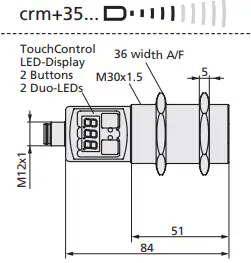
crm+35/DD/TC/E
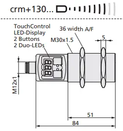
crm+130/DD/TC/E
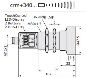
crm+340/DD/TC/E
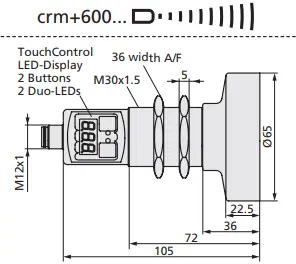
crm+600/DD/TC/E
Product description
- The crm+ sensor with two switching outputs measures the distance to an object within the detection zone contactless. Depending on the adjusted detect distance the switching output is set.
- The ultrasonic transducer surface of the crm+ sensors is laminated with a PEEK film. The transducer itself is sealed against the housing by a PTFE joint ring. This composition ensures a high resitance against many aggressive substances.
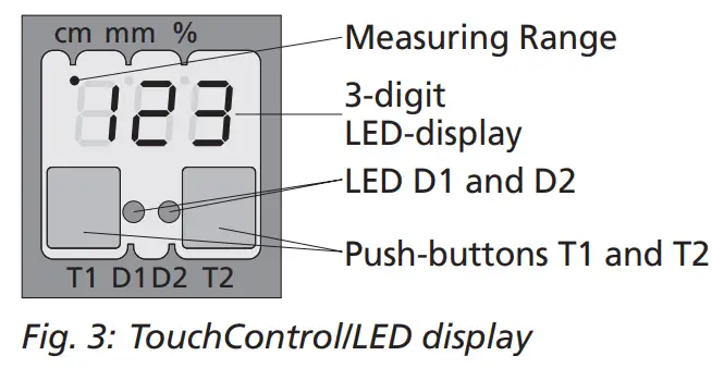
- All settings are done with two pushbuttons and a three-digit LED-display (TouchControl).
- Three-colour LEDs indicate the switching status.
- The output functions are changeable from NOC to NCC.
- The sensors are adjustable manually via TouchControl or via Teach-in procedure.
- Useful additional functions are set in the Add-on-menu.
- Using the LinkControl adapter (optional accessory) all TouchControl and additional sensor parameter settings can be adjusted by a Windows® Software.
The crm+ sensors have a blind zone in which distance measurement is not possible. The operating range indicates the distance of the sensor that can be applied with normal
reflectors with sufficient function reserve. When using good reflectors, such as a calm water surface, the sensor can also be used up to its maximum range. Objects that strongly absorb (e.g. plastic foam) or diffusely reflect sound (e.g. pebble stones) can also reduce the defined operating range.
Safety Notes
- Read the operating instructions prior to start-up.
- Connection, installation and adjustment works may only be carried out by expert personnel.
- No safety component in accordance with the EU Machine Directive, use in the area of personal and machine protection not permitted
Proper Use
crm+ ultrasonic sensors are used for non-contact detection of objects.
Synchronisation
If the assembly distances shown in Fig. 1 for two or more sensors are exceeded the integrated synchronisation should be used. Connect Sync/Comchannels (pin 5 at the units
receptable) of all sensors (10 maximum).
 | ||
| crm+25… crm+35… crm+130… crm+340… crm+600… | ≥0.35 m ≥0.40 m ≥1.10 m ≥2.00 m ≥4.00 m | ≥2.50 m ≥2.50 m ≥8.00 m ≥18.00 m ≥30.00 m |
Fig. 1: Assembly distances, indicating synchronisation/multiplex
Multiplex mode
The Add-on-menu allows to assign an individual address »01« to »10« to each sensor connected via the Sync/ Com-channel (Pin5). The sensors perform the ultrasonic measurement sequentially from low to high address. Therefore any influence between the sensors is rejected. The address »00« is reserved to synchronisation mode and eactivates the multiplex mode. To use synchronised mode all sensors must be set to address »00«.
Installation
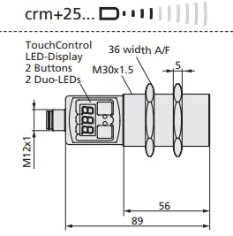
![]() Assemble the sensor at the installation location.
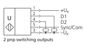
Assemble the sensor at the installation location.![]() Plug in the connector cable to the M12 connector, see Fig. 2.
Plug in the connector cable to the M12 connector, see Fig. 2.
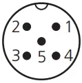 |  | colour |
| 1 | +UB | brown |
| 3 | –UB | blue |
| 4 | D2 | black |
| 2 | D1 | white |
| 5 | Sync/Com | grey |
Fig. 2: Pin assignment with view onto sensor plug and colour coding of the microsonic connection cable
Start-up![]() Connect the power supply.
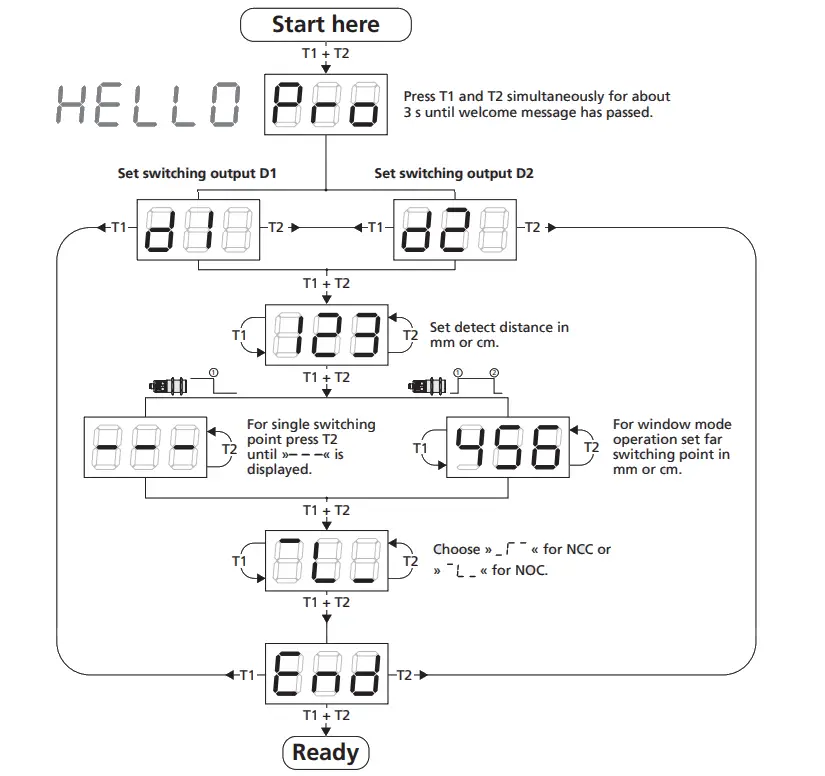
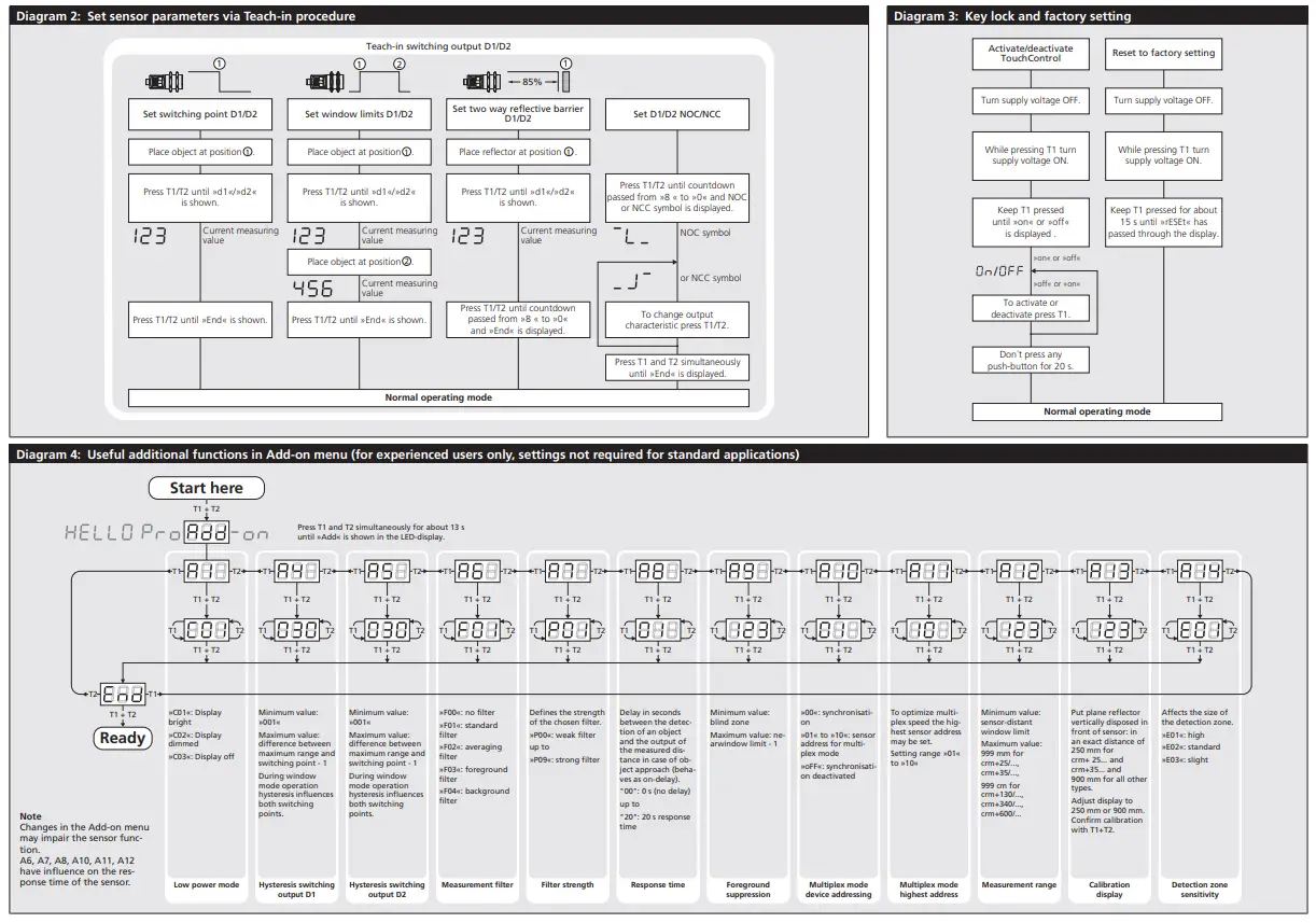
Connect the power supply.![]() Set the parameters of the sensor manually via TouchControl (see Fig. 3 and Diagram 1)
Set the parameters of the sensor manually via TouchControl (see Fig. 3 and Diagram 1)![]() or use the Teach-in procedure to adjust the detect points (see Diagram 2).
or use the Teach-in procedure to adjust the detect points (see Diagram 2).
Factory setting
crm+ sensors are delivered factory made with the following settings:
- Switching outputs on NOC
- Detecting distance at operating range and half operating range
- Measurement range set to maximum range
Maintenance
crm+ sensors work maintenance free.
Small amounts of dirt on the surface do not influence function. Thick layers of dirt and caked-on dirt affect sensor function and therefore must be removed.
Notes
- As a result of the design the assembly of PEEK film and PTFE joint ring is not gas-proof.
- The chemical resistance has to be tested experimentally if necessary.
- crm+ sensors have internal temperature compensation. Because the sensors heat up on their own, the temperature compensation reaches its optimum working point after approx. 30 minutes of operation.
- During normal operating mode, a yellow LED D2 signals that the switching output has connected.
- During normal operating mode, the measured distance value is displayed on the LED-indicator in mm (up to 999 mm) or cm (from 100 cm). Scale switches automatically and is indicated by a point on top of the digits.
- During Teach-in mode, the hysteresis loops are set back to factory settings.
- If no objects are placed within the detection zone the LED-indicator shows »– – –«.
- If no push-buttons are pressed for 20 seconds during parameter setting mode the made changes are stored and the sensor returns to normal operating mode.
- The sensor can be reset to its factory setting, see »Key lock and factory setting«, Diagram 3.
Show parameters![]() In normal operating mode shortly push T1. The LED display shows »PAr.«
In normal operating mode shortly push T1. The LED display shows »PAr.«
Each time you tap push-button T1 the actual settings of the analogue output are shown.
Technical data
 |  |  |  |  |  |
| blind zone | 0 to 30 mm | 0 bis 85 mm | 0 to 200 mm | 0 to 350 mm | 0 to 600 mm |
| operating range | 250 mm | 350 mm | 1,300 mm | 3,400 mm | 6,000 mm |
| maximum range | 350 mm | 600 mm | 2,000 mm | 5,000 mm | 8,000 mm |
| angle of beam spread | see detection zone | see detection zone | see detection zone | see detection zone | see detection zone |
| transducer frequency | 320 kHz | 360 kHz | 200 kHz | 120 kHz | 80 kHz |
| resolution | 0.025 mm | 0.025 mm | 0.18 mm | 0.18 mm | 0.18 mm |
| detection zones for different objects: The dark grey areas represent the zone where it is easy to recognise the normal reflector (round bar). This indicates the typical operating range of the sensors. The light grey areas represent the zone where a very large reflector – for instance a plate – can still be recognised. The requirement here is for an optimum alignment to the sensor. It is not possible to evaluate ultrasonic reflections outside this area. | 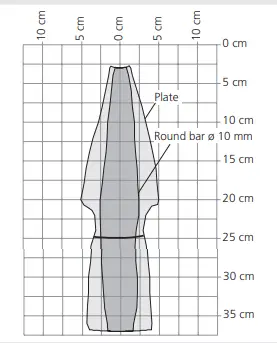 | 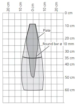 | 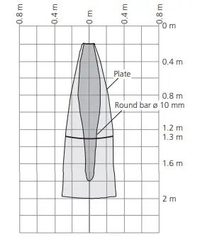 | 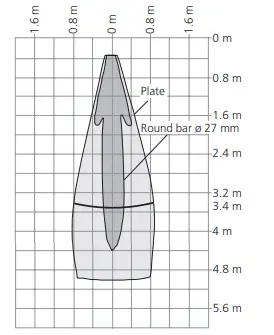 | 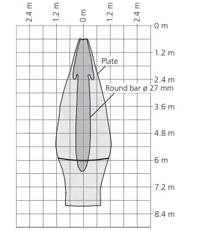 |
| reproducibility | ±0.15 % | ±0.15 % | ±0.15 % | ±0.15 % | ±0.15 % |
| accuracy | ±1 % (Temperature drift internal compensated, may be deactivated 3),0.17%/K without compensation) | ±1 % (Temperature drift internal compensated, may be deactivated 3),0.17%/K without compensation) | ±1 % (Temperature drift internal compensated, may be deactivated 3), 0.17%/K without compensation) | ±1 % (Temperature drift internal compensated, may be deactivated 3), 0.17%/K without compensation) | ±1 % (Temperature drift internal compensated, may be deactivated 3), 0.17%/K without compensation) |
| operating voltage UB | 9 to 30 V DC, short-circuit-proof, Class 2 | 9 to 30 V DC, short-circuit-proof, Class 2 | 9 to 30 V DC, short-circuit-proof, Class 2 | 9 to 30 V DC, short-circuit-proof, Class 2 | 9 to 30 V DC, short-circuit-proof, Class 2 |
| voltage ripple | ±10 % | ±10 % | ±10 % | ±10 % | ±10 % |
| no-load supply current | ≤ 80 mA | ≤ 80 mA | ≤ 80 mA | ≤ 80 mA | ≤ 80 mA |
| housing | Stainless steel 1.4571, plastic parts: PBT, TPU; Ultrasonic transducer: PEEK film, PTFE epoxy resin with glass content | Stainless steel 1.4571, plastic parts: PBT, TPU; Ultrasonic transducer: PEEK film, PTFE epoxy resin with glass content | Stainless steel 1.4571, plastic parts: PBT, TPU;Ultrasonic transducer: PEEK film, PTFE epoxy resin with glass content | Stainless steel 1.4571, plastic parts: PBT, TPU;Ultrasonic transducer: PEEK film, PTFE epoxy resin with glass content | Stainless steel 1.4571, plastic parts: PBT, TPU; Ultrasonic transducer: PEEK film, PTFE epoxy resin with glass content |
| class of protection to EN 60529 | IP 67 | IP 67 | IP 67 | IP 67 | IP 67 |
| norm conformity | EN 60947-5-2 | EN 60947-5-2 | EN 60947-5-2 | EN 60947-5-2 | EN 60947-5-2 |
| type of connection | 5-pin initiator plug, PBT | 5-pin initiator plug, PBT | 5-pin initiator plug, PBT | 5-pin initiator plug, PBT | 5-pin initiator plug, PBT |
| controls | 2 push-buttons (TouchControl) | 2 push-buttons (TouchControl) | 2 push-buttons (TouchControl) | 2 push-buttons (TouchControl) | 2 push-buttons (TouchControl) |
| indicators | 3-digit LED display, 2 three-colour LEDs | 3-digit LED display, 2 three-colour LEDs | 3-digit LED display, 2 three-colour LEDs | 3-digit LED display, 2 three-colour LEDs | 3-digit LED display, 2 three-colour LEDs |
| programmable | with TouchControl and LinkControl | with TouchControl and LinkControl | with TouchControl and LinkControl | with TouchControl and LinkControl | with TouchControl and LinkControl |
| operating temperature | –25 to +70 °C | –25 to +70 °C | –25 to +70 °C | –25 to +70 °C | –25 to +70 °C |
| storage temperature | –40 to +85 °C | –40 to +85 °C | –40 to +85 °C | –40 to +85 °C | –40 to +85 °C |
| weight | 150 g | 150 g | 150 g | 210 g | 270 g |
| switching hysteresis 1) | 3 mm | 5 mm | 20 mm | 50 mm | 100 mm |
| switching frequency 2) | 25 Hz | 12 Hz | 8 Hz | 4 Hz | 3 Hz |
| response time 2) | 32 ms | 64 ms | 92 ms | 172 ms | 240 ms |
| time delay before availability | <300 ms | <300 ms | <300 ms | <380 ms | <450 ms |
| order No. | crm+25/DD/TC/E | crm+35/DD/TC/E | crm+130/DD/TC/E | crm+340/DD/TC/E | crm+600/DD/TC/E |
| switching output | 2 x pnp, UB – 2 V, Imax = 2 x 200 mA switchable NOC/NCC, short-circuit-proof | 2 x pnp, UB – 2 V, Imax = 2 x 200 mA switchable NOC/NCC, short-circuit-proof | 2 x pnp, UB – 2 V, Imax = 2 x 200 mA switchable NOC/NCC, short-circuit-proof | 2 x pnp, UB – 2 V, Imax = 2 x 200 mA switchable NOC/NCC, short-circuit-proof | 2 x pnp, UB – 2 V, Imax = 2 x 200 mA switchable NOC/NCC, short-circuit-proof |
microsonic GmbH / Phoenixseestraße 7 / 44263 Dortmund / Germany /
T +49 231 975151-0 / F +49 231 975151-51 /
E [email protected] /
W microsonic.de
The content of this document is subject to technical changes.
Specifications in this document are presented in a descriptive way only.
They do not warrant any product features.

Enclosure Type 1
For use only in industrial
machinery NFPA 79 applications.
The proximity switches shall be used with a
Listed (CYJV/7) cable/connector assembly rated
minimum 32 Vdc, minimum 290 mA, in the final installation.