ALLEGION XE360 Series Wireless Lock User Guide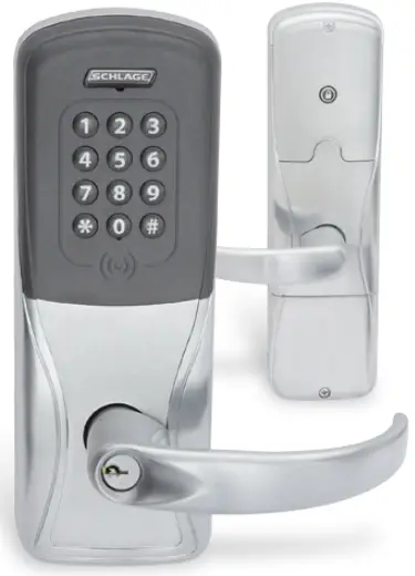
Introduction
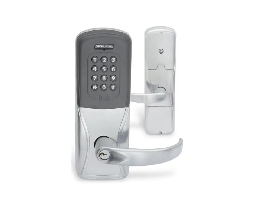
Lock diagrams
XE360-EW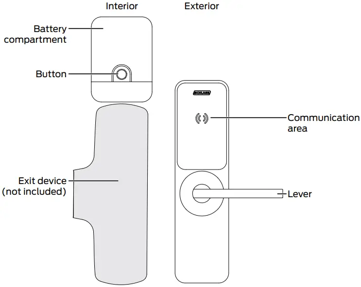
XE360-M and XE360-T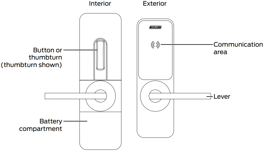
Power
XE360-EW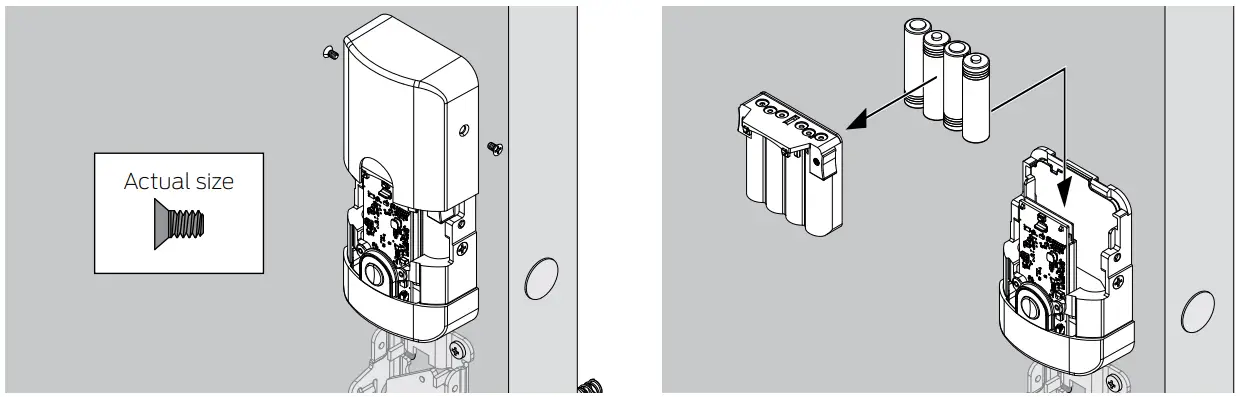
XE360-M/XE360-T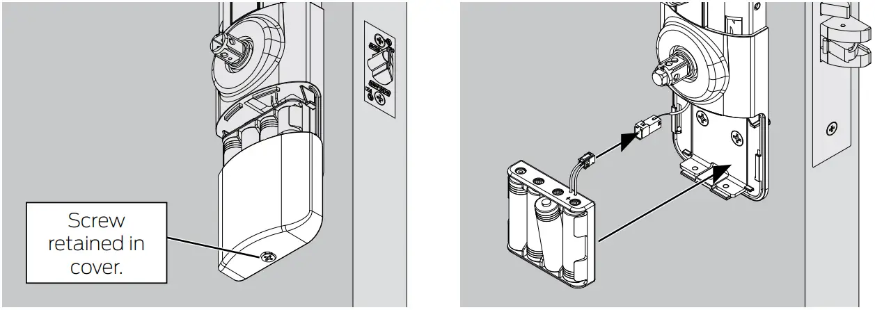
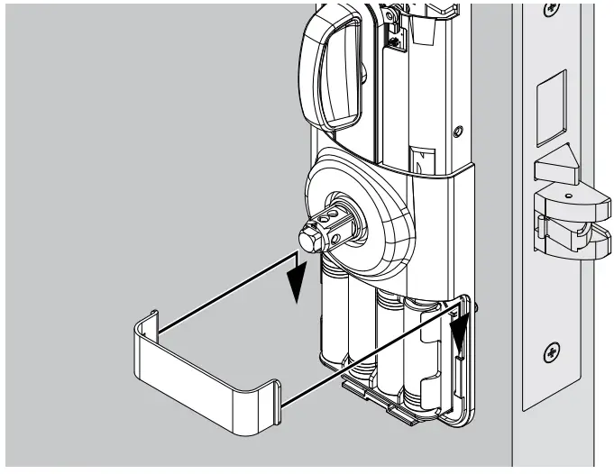
Insert batteries as shown. Replace batteries as necessary after the low battery warning, or on a set schedule to ensure
continuous operation.
- Use standard alkaline batteries. Lithium batteries are not recommended as there is little warning before the battery voltage is
too low for continued operation.
Commissioning
Commissioning is the process of adding the lock into the access control system. Once commissioned, the lock(s) can be controlled using Allegion Engage™.
- Power the lock. The initiation sequence will begin. Wait for a steady blue light and one (1) beep.
- Press and release the mode switch to enter manual commissioning mode.
- Open the Engage Mobile Application and follow the steps to connect the lock.
- The lock will blink one (1) long blue light when commissioning is complete.
The lock will be displayed in the app. - Once the sequence is complete, the lock will disconnect. The lock will now operate in normal mode.

Lock modes
Normal mode
Once the lock is commissioned, it can be controlled using Allegion Engage.
Multi-family construction mode
When in multi-family construction mode, the lock may be unlocked by presenting any credential with the same 48X-type and facility code.
- While the lock is in FDR mode, press and hold the mode switch for three (3) seconds. The lock will blink one (2) green
light, and beep one (1) time, and enter construction mode. - Within twenty (20) seconds, present a 48X-type credential, with a valid facility code, to the lock. The lock will blink four
(4) green lights and beep one time. - The lock will now operate in multi-family construction mode.
Commercial construction mode
When in commercial construction mode, the lock may be unlocked by presenting a registered credential.
- While the lock is in FDR mode, press and hold the mode switch for three (3) seconds. The lock will blink one (1) green
light, and beep one (1) time, and enter construction mode. - Within twenty (20) seconds, press and hold the mode switch and present a master credential to the lock. Then release
the mode switch. The lock will blink five (5) green lights and beep one time.
The lock will now operate in commercial construction mode.
Register a commercial construction credential
- While in Commercial construction mode, present a master credential to the lock. The lock will blink one (1) green light
and beep one (1) time. - Present a new credential to the lock. This credential will become a registered commercial construction mode credential.
- This credential may now be used to unlock the lock.
Diagnostics and Troubleshooting
| Troubleshooting | |
| Problem | Solution |
| Manual commissioning failed. | When commissioning fails, the lock will revert to FDR mode. Press and release the mode switch again to restart the process.
|
| During commissioning, the blue light went out. |
|
| DPS not responding |
|
| REX not responding |
|
| Glossary and acronyms | |
| Term | Definition |
| Advertising | the lock state in which the lock is sending out a Bluetooth signal so that it may be commissioned. Once initiated, the lock will advertise for tow (2) minutes. |
| Commissioning | adding the lock into the access control system |
| FDR | Factory default reset |
| FDR mode | the lock state in which the lock is set to factory settings |
| DP | door position switch |
| REX | request for exit |
| Lock indicators | |||
| Function | Actions | Lights | Beeps |
| Initialization complete | 3 green short | — | |
| Valid credential presented | Lock unlock | 1 green | 1 |
| Factory default reset (FDR) | Mode activated | red on | 1 |
| Timeout | 2 red long | 2 | |
| Lock FDR initiated | 2 red short | 2 | |
| Reader FDR initiated | 3 red short | 3 | |
| In progress | solid red | — | |
| Not successful | 2 red long | 2 | |
| Successful | 1 green long | 1 long | |
| Lock indicators | |||
| Function | Actions | Lights | Beeps |
| Contraction mode | Mode initiated | green on | 1 |
| Construction mode activated | 5 green fast | 1 | |
| Timeout | 2 red long | — | |
| Test mode | Mode activated | yellow on | steady |
| Manual commissioning mode | Advertising | blue on | 1 |
| MAPP connected | 1 blue long | — | |
| Door position sensor (DPS) | Door open | 1 blue | 1 |
| Door closed | 2 blue | 2 | |
| Request for exit (REX) | REX closed | 1 yellow fast | 1 |
| REX open | 2 yellow fast | 2 | |
| Internal push button (IPB) | Door unlocked with IPB | 1 green | 1 |
| Door locked | 2 red | 1 | |
| Low battery warning | Batteries need to be replaced | 9 red | — |
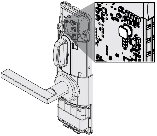
Factory default reset (FDR)
- Remove lock cover.
- Press and hold button for seven (7) seconds, until light turns red.
- Initiate FDR:
- To perform FDR on the lock, press the button one (1) time. Lock will blink red two (2) times and beep two (2) times.
- To perform FDR on the reader, press the button two (2) times. Lock will blink red three (3) times and beep three (3)
times.
- Wait for one (1) long green light and one (1) long beep to confirm successful FDR.
- FDR was not successful if lock blinks red two (2) times and beeps two (2) times.
DPS (door position switch)
To ensure the DPS is working properly, follow these diagnostic steps:
- Power lock and wait for the steady blue light.
- Press and release the mode switch to stop the lock from advertising.
- The lock should blink one blue light and beep one time on both sides of the door to indicate open.
- The lock should blick two blue lights and beep two times on both side of the door to indicate closed.
- See Troubleshooting if lock is not responding as described.
REX (request for exit)
- Power lock and wait for the steady blue light.
- Press and release the mode switch to stop the lock from advertising.
- The lock should blink one yellow light and beep one time on both sides of the door to indicate closed.
- The lock should blink two yellow lights and beep two times on both sides of the door to indicate closed.
- See Troubleshooting if lock is not responding as described.
Troubleshooting
| Troubleshooting | |
| Problem | Solution |
| Manual commissioning failed. | When commissioning fails, the lock will revert to FDR mode. Press and release the mode switch again to restart the process.
|
| DPS not responding |
|
| REX not responding |
|
Factory default reset
- Remove lock cover.
- Press and hold button for seven (7) seconds, until light turns red.
- Initiate FDR:
- To perform FDR on the lock, press the button one (1) time. Lock will blink red two (2) times and beep two (2) times.
- To perform FDR on the reader, press the button two (2) times. Lock will blink red three (3) times and beep three (3) times.
- Wait for one (1) long green light and one (1) long beep to confirm successful FDR.
- FDR was not successful if lock blinks red two (2) times and beeps two (2) times.
FCC Statements
FCC Compliance Statements
- This device complies with Part 15 of the FCC Rules. Operation is subject to the following two conditions: (1) this device may not cause harmful interference, and (2) this device must accept any interference received, including interference that may cause undesired operation.
- Changes or modifications not expressly approved by Schlage Lock Company could void the user’s authority to operate the equipment.
- This equipment has been tested and found to comply with the limits for a Class B digital device, pursuant to Part 15 of the FCC Rules. These limits are designed to provide reasonable protection against harmful interference in a residential installation. This equipment generates, uses and can radiate radio frequency energy and, if not installed and used in accordance with the instructions, may cause harmful interference to radio communications. However, there is no guarantee that interference will not occur in a particular installation. If this equipment does cause harmful interference to radio or television reception, which can be determined by turning the equipment off and on, the user is encouraged to try to correct the interference by one or more of the following measures:
- Reorient or relocate the receiving antenna.
- Increase the separation between the equipment and receiver.
- Connect the equipment into an outlet on a circuit different from that to which the receiver is connected.
- Consult the dealer or an experienced radio/TV technician for help
FCC Labeling Requirements
- Exterior of product must include “Contains Transmitter Module FCC ID: XPB-OEM 200-XXXX”where XXXX is the model included in the installation.
| OEM 200 Model | FCC Certification Number |
| 80mm Multi-Tech | XPB-OEM 200-80MT |
| 80mm Smart Only | XPB-OEM 200-80SM |
| 90mm Multi-Tech | XPB-OEM 200-90MT |
| 90mm Smart Only | XPB-OEM 200-90SM |
FCC Integration Requirements
- The FCC/IC Statements contained in this guide must also be included in the final product’s documentation.
- Applicable standards are 15.225, 15.209, and RSS-210.
- For the purposes of compliance testing, it may be necessary to put the OEM 200 Module into a ‘constant read’ mode. In order to achieve this, present an Anti-Passback configuration card within the first minute of the module being powered. If performed correctly, the module will reboot and presenting a credential will result in constant reading and rereading of
a credential as long as it remains in the operating volume of the antenna. This differs from normal operation in that when a credential is polled for a second time under normal operation the credential data is not output as it is seen as redundant. - Take care to NOT to place the OEM 200 antenna boards near other wireless antennas as they may cause interference with each other and result in the need for additional RF testing. Preferred distance is three (3) inches from other wireless transceivers.
- The OEM 200 is only FCC authorized for the specific rule parts listed on the grant (the applicable standards from note #2). The host product manufacturer is responsible for compliance to any other FCC rules that apply to the host not covered by the modular transmitter grant of certification.
IC Statements
IC Compliance Statements
This device contains license-exempt transmitter(s)/receiver(s) that comply with Innovation, Science and Economic Development Canada’s license-exempt RSS(s). Operation is subject to the following two conditions:
- This device may not cause interference.
- This device must accept any interference, including interference that may cause undesired operation of the device.
IC Labelling Requirements
- The host product shall be properly labelled to identify the modules within the host product.
The ISED certification label of a module shall be clearly visible at all times when installed in the host product; otherwise, the host product must be labelled to display the ISED certification number for the module, preceded by the word “contains” or similar wording expressing the same meaning, as follows:
Contains IC: XXXXXX-YYYYYYYYYYY
Where XXXXX-YYYYYYYYYY is one of the ISED certification numbers form the following table
| OEM 200 Model | ISED Certification Number |
| 80mm Multi-Tech | 8053B-OEM 20080MT |
| 80mm Smart Only | 8053B-OEM 20080SM |
| 90mm Multi-Tech | 8053B-OEM 20090MT |
| 90mm Smart Only | 8053B-OEM 20090SM |
Warnings and cautions
![]() WARNING
WARNING
Warnings indicate potentially hazardous conditions, which if not avoided or corrected, may cause death or serious injury.
![]() CAUTION
CAUTION
Cautions indicate potentially hazardous conditions, which if not avoided or corrected, may cause minor or moderate injury.
Cautions may also warn against unsafe practices.
NOTICE
Notices indicate a condition that may cause equipment or property damage only
About Allegion
Allegion (NYSE: ALLE) is a global pioneer in seamless access, with leading brands like CISA®, Interflex®, LCN®, Schlage®, SimonsVoss® and Von Duprin®. Focusing on security around the door and adjacent areas, Allegion secures people and assets with a range of solutions for homes, businesses, schools and institutions. Allegion had $2.9 billion in revenue in 2019 and sells products in almost 130 countries.
For more, visit www.allegion.com
Contact information
Should a system design engineer or developer need assistance, they should contact technical support at:
Phone: 1-877-671-7011
www.allegion.com/us
MIFARE® and DESFire™ are registered trademarks of NXP B.V