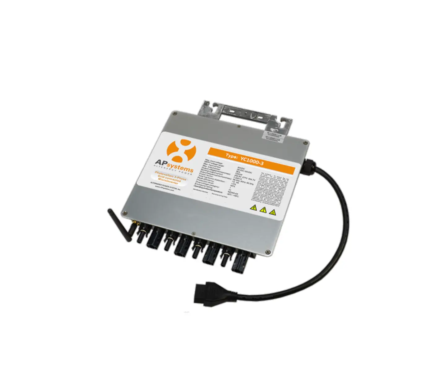
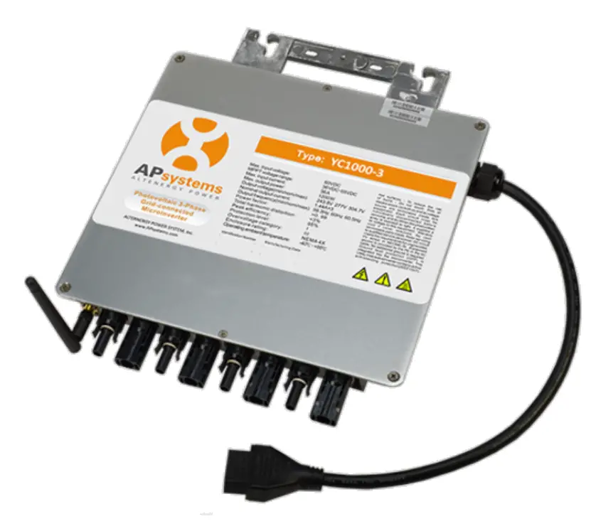
APsystems YC1000-3-NA 3 Phase Microinverter
Quick Installation
The sketch of YC1000-3 support system.
All the PV modules are placed into two lines. Then put a YC1000-3 in the middle of the two lines and make sure it is easy to connect with four PV modules which are next to it, as well all the cables.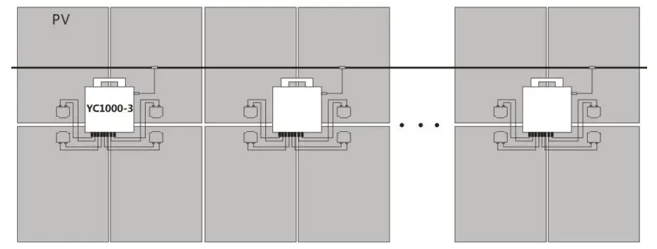
Step 1. Verify the grid voltage to match with microinverter rating.
Step 2. Lay the AC bus according to the arrangement of APsystems Microinverter.
Step 3. Attach the APsystems Microinverters to the racking.
NOTE: Do not place the inverters (including DC and AC connectors) where exposed to the sun, rain or snow, even gap between modules. Allow a minimum of 3/4”(1.5cm.) between the roof and the bottom of the Microinverter to allow proper air flow.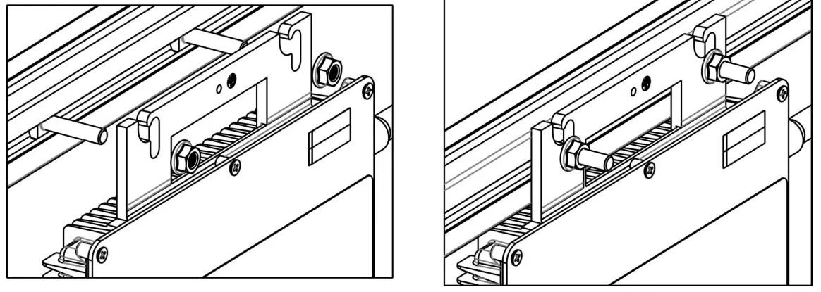
Step 4. Connect the APsystems Microinverter cables to the AC bus cable.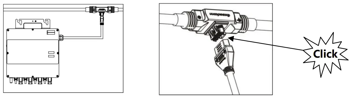
NOTE: AC connector interface as follows, from left to right PE, N, L3, L2, L1.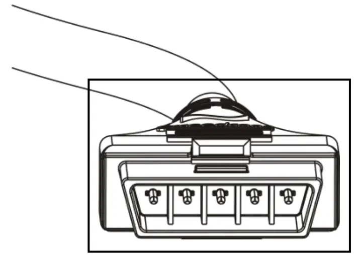
NOTE: Cover all unused T connectors with Bus Cable End Cap to protect the T connectors.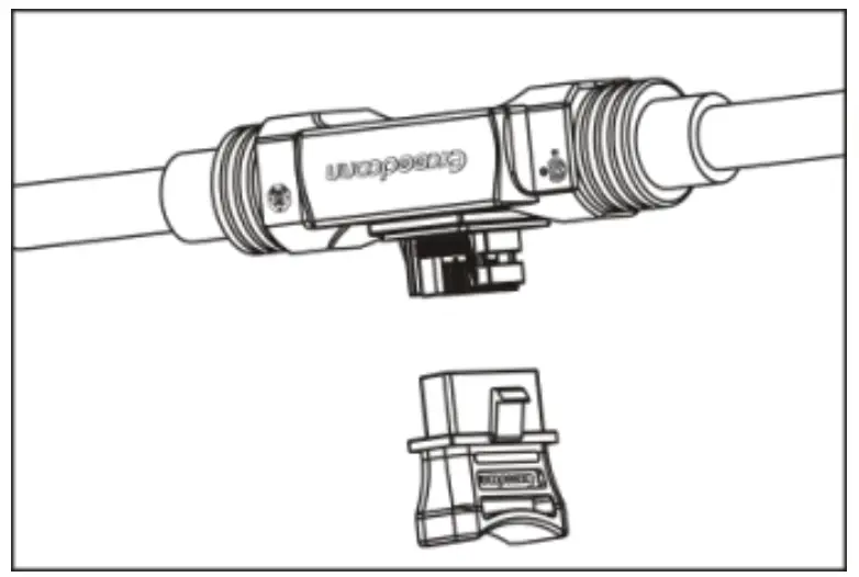
Step 5. Place the PV modules and connect each YC1000 to four PV modules close-by.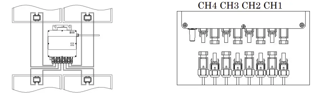
Step 6. Install a protective end cap at the end of AC bus cable.
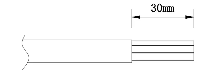
- Wire stripping

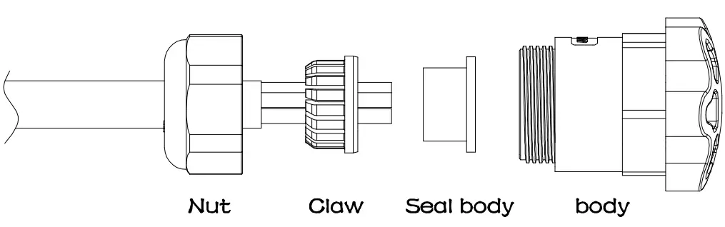
- Set the parts on the cable.

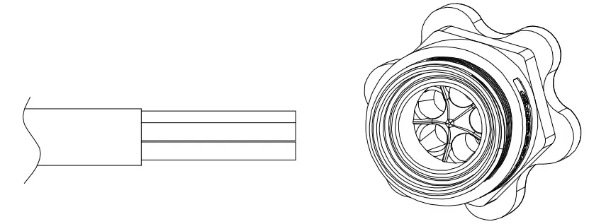
- Insert five wires into the core wires hole of the body.

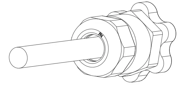
- Insert seal and Clamp Finger into the body ,then tighten the nut, torque 2.5±0.5NM.

Step 7. Install the AC branch circuit junction box.
Step 8. Connect the cables to the branch junction box.
a. Put the unused end of the AC interconnector cable into the branch junction box.
b. Place cable connecting to the point of load interconnection into the branch junction box.
c. Wire the conductors of the AC bus: BLACK-L1; RED-L2; BLUE-L3; WHITE-N; GREEN-PE.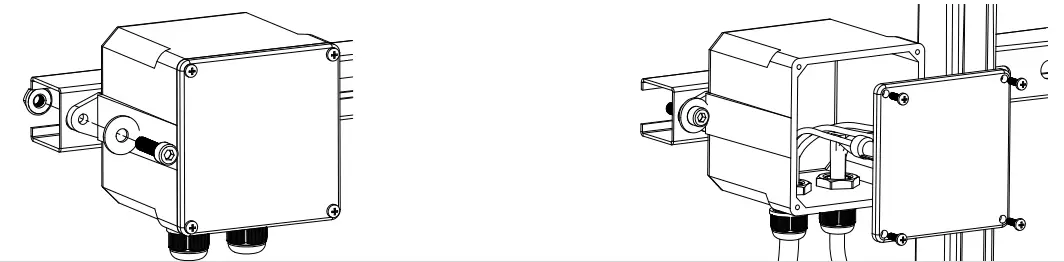
NOTE: Wiring colour code can be different according local regulation, check all the wires of the installation before connecting to the AC bus to be sure they match. Wrong cabling can damage irreparably the microinverters, such an issue is not covered by the warranty.
NOTE: The neutral line from the inverter is NOT allowed to be floating, MUST be
Step 9. Complete the APsystems installation map.
Each APsystems micro inverter has two removable serial number labels. Peel labels off, affix one to the respective location on the APsystems installation map, and affix another to the PV module frame which is easy to see. Use the Scanning Gun to scan the serial numbers on the map into the computer or scan by mobile phone with APsystems Array App, then complete the setting (see ECU manual).
NOTE: Step 1~9 can change sequence for convenience of installation.
Step 10. Start the operation.
- Turn on the AC circuit breaker on each microinverter AC branch circuit.
- Turn on the main utility-grid AC circuit breaker. Your system will start producing power after a five-minute waiting time
Product information is subject to change without notice.
(Please download manuals at www.APsystems.com).