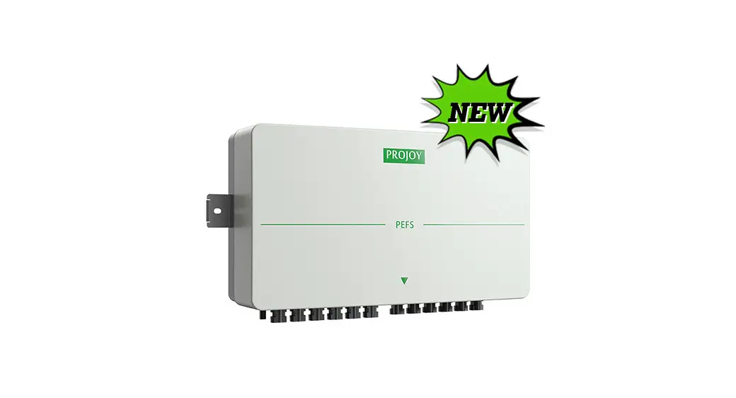
![]() PEFS-24V-CN Series Panel Level Rapid Shutdown Control Box
PEFS-24V-CN Series Panel Level Rapid Shutdown Control Box
Installation Guide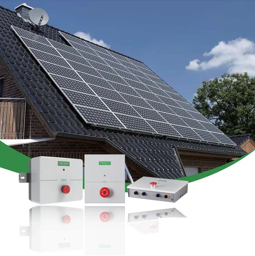
Scope and General
The manual only used to PEFS-24V-CN Series Panel-level Rapid Shutdown(DC 24V) Control Box.
| Version | Date | Remark | Chapter |
| V1.0 | 2021-10-15 | First Edition | – |
| V2.0 | 2022-04-20 | Content Modified | 4 Installation & Connection/ 5 Technical Specification |
| V3.0 | 2022-06-02 | Content Modified | 3 Introduction 4 Installation & Connection/ 5 Technical Specification |
Important Safety Precautions
2.1 Disclaimer:
PROJOY assumes no responsibility for any loss, in particular for circuit damage, resulting from any violation of the specifications recommended and referred to in this specification. PROJOY assumes no responsibility for the damage of the product caused by the maintenance, improper use, wrong installatio,n or wrong system design of the product by non-designated personnel.
2.2 Safety instructions:
- PEFS is an electrical product that should be installed by a suitable person who meets local regulations.
- When modifying an existing installation, isolate the inverter from the PV array by turning OFF the DC isolator/switch disconnect or turning OFF the inverter and the AC switch.
- Incorrect connections to the PEFS-24V-CN may cause failure.
2.3 Cautions:
If the inverter and PV module connectors are not compatible with PEFS connectors, forced connections are unsafe and may cause operational problems.
For the mechanical compatibility of the module/converter and PEFS, use the same connectors from the same manufacturer on both the PEFS and modules, or obtain verification that the connectors to be used are compatible.
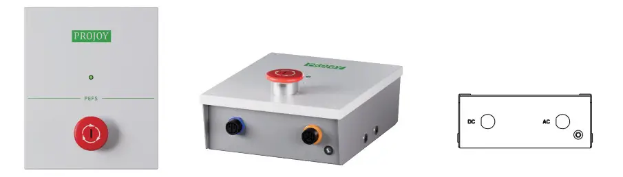
Introduction
Control Box includes Power Supply
- PEFS-24V-C60

- PEFS-24V-C180

Control Box External Power Supply
- PEFS-24V-C480

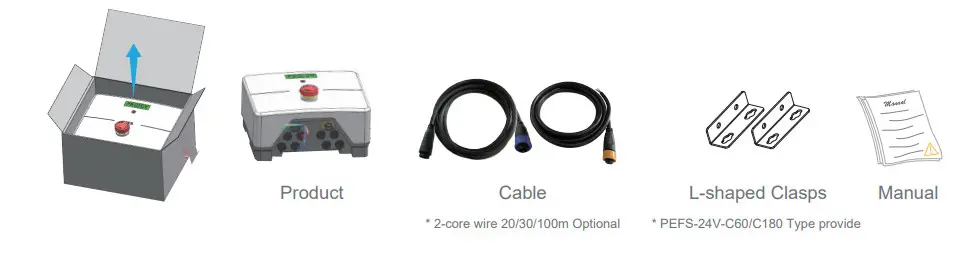
Installation & Connection
- Open the box, take out PEFS-24V-CN and parts, read this manual.

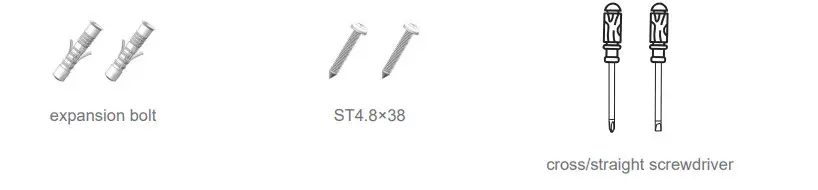
- Prepare materials and tools.

- The installation modes of PEFS-24V-CN are divided into the following two situations.
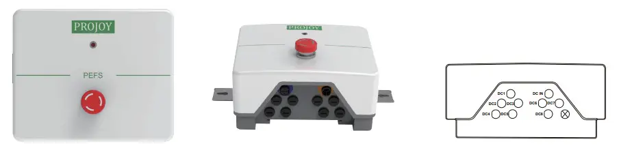
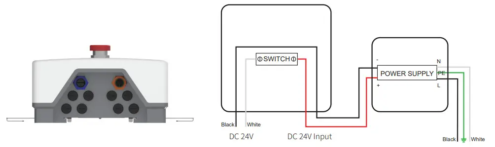
Control Box includes Power Supply (Take PEFS-24V-C60 as an example)
a) Align the round hole of the L-shaped clasp with the round hole of the box and fix them with screws.
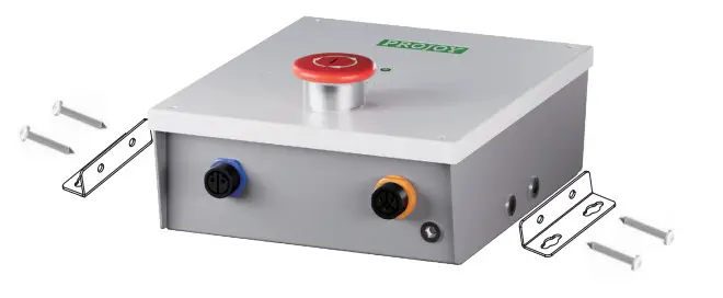
b) Mount the control box to the appropriate location through the gourd-shaped hole.
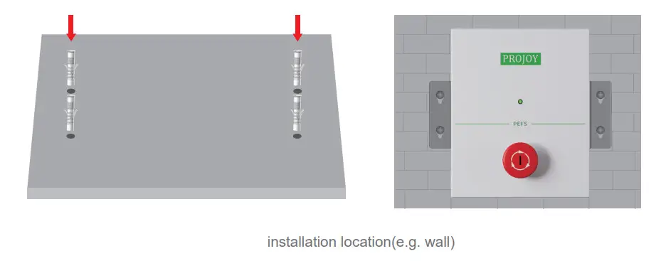
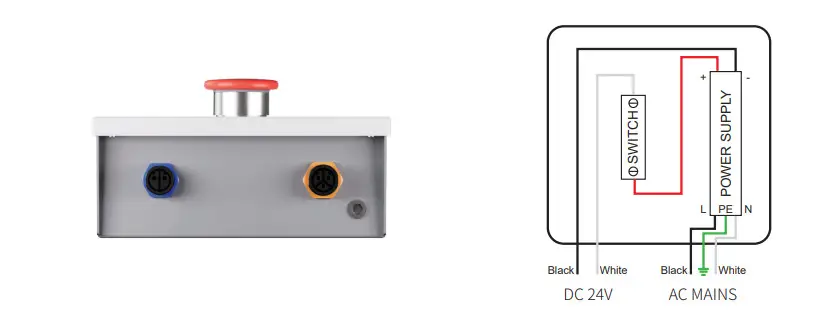
c) Wring.
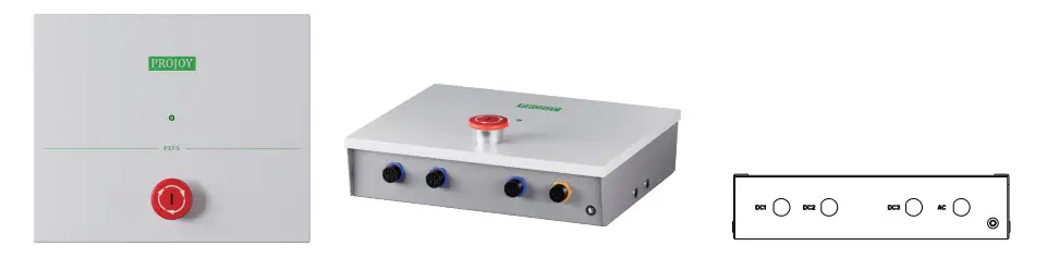
Control Box External Power Supply (PEFS-24V-C480)
a) Pull out the clasps to both sides.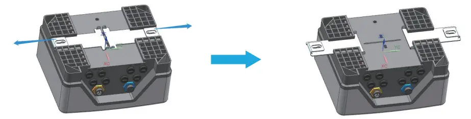
b) Mount the control box to the appropriate location through the gourd-shaped hole.
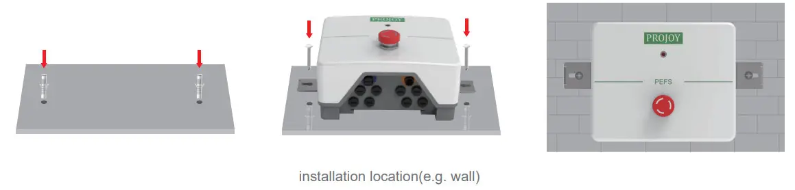
c) Wiring
PEFS-24V-C480 does not have a power supply, so an external power supply is required to power the control box.
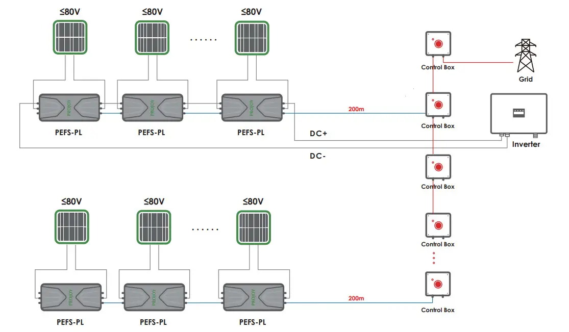
Parallel connection of multiple control boxes
Technical Specification
Control Box (Include Power Supply)
| Model | PEFS-24V-C60 | I PEFS-24V-C180 |
| Operating AC Voltage Range | 100 V 240 V | |
| Nominal Frequency | 50/60 Hz | |
| Output Voltage | 24V DC | |
| Max. Output Current | 2.2A | 1 8.8A |
| 24Vdc Control Cable Size | 0.823 mm2 / 18 AWG | |
| 24Vdc Control Cable Length With Standard Connectors | 20m/30 m/100 m | |
| Spare Terminal Connectors | Yes | |
| Maximum PEFS-PL80S-11 | 60 Units | 180 Units |
| Maximum PEFS-PL80S-21 | 30 Units | 90 Units |
| Dimensions (mm) | 155’188’63 | 265’218’63 |
| With Lock | Optional (IP54) | |
| Operating Temperature Range | -30 C — +70 C | |
| Protection Class | IP65 | |
| Mounting | Wall Mounted | |
| Maximum Distance (Last RSD to Controller Box) | 200m | |
Control Box (External Power Supply)
| Model | PEFS-24V-C480 | |
| Operating AC Voltage Range | 100 V-240 V | |
| Nominal Frequency | 50/60 Hz | |
| Output Voltage | 24V DC | |
| Output Current / Per String | 2.2A | |
| 24Vdc Control Cable Size | 0.823 mm2 / 18 AWG | |
| 24Vdc Control Cable Length With Standard Connectors | 20 m / 30 m 1100 m | |
| Spare Terminal Connectors | Yes | |
| Maximum PEFS-PL80S-11 / Per String | 60 Units | |
| Maximum PEFS-PL80S-21 / Per String | 30 Units | |
| Dimensions (mm) | 210’175’105 | |
| With Lock | Optional | |
| Operating Temperature Range | -30 C — +70 C | |
| Protection Class | IP65 | |
| Mounting | Wall Mounted | |
| Maximum Distance (Last RSD to Controller Box) | 200m | |
| Recommend Power Supply | Output Current | 20A |
| Maximum PEFS-PL80S-11 | 480 Units | |
| Maximum PEFS-PL80S-21 | 240 Units | |
Trouble Shooting
Control Box (Include Power Supply)
| Problem | Possible Cause | Possible Solution |
| Panel (pair) voltage is OV | No mains supply | Check area utility operational |
| (LED OFF) | Check mains ON | |
| Check mains fuse | ||
| PEFS-24V-CN power supply failure | Check mains voltage between L&N marked terminals | |
| Check 24VDC between + & – marked terminals | ||
| PEFS-24V-CN switch activated | Turn the red actuator anti-clockwise to release the button | |
| No PEFS-24V-CN switch output | Check 24VDC between switch out terminal & PSU — marked terminal | |
| Broken cable | Check 24VDC between terminals of remote AMP | |
| Superseal connector (pin 1 +24VDC\pin 2 OVDC) | ||
| PV array not connected | Check all PV to PEFS-24V-CN input connections | |
| Incorrect PEFS-24V-CN polarity connection | Check PV array Positive (+) goes to PEFS-24V-CN | |
| Positive (+) and PV array Negative (-) goes to PEFS-PC Negative (-) | ||
| No PEFS-24V-CN output | Replace PEFS-24V-CN | |
| PV Inverter input OV | No DC isolator (if fitted) | Check PEFS-24V-CN output connections |
| input | Check DC inputs to the isolator | |
| DC Isolator (if fitted) OFF | Turn DC Isolator ON | |
| String voltage too low | Incorrect PEFS-24V-CN polarity connection | Check all PV array Positive (+) go to PEFS-PC |
| Positive (+) and PV array Negative (-) goes to PEFS-PC Negative (-) |
In the occurrence of a fire, PROJOY recommends that all elements of the PEFS Rapid Shutdown system be assessed for operational suitability by a competent person prior to re-energizing.
Aftersales service and warranty
This product is manufactured in a sophisticated quality management system. In case of fault, the following warranty and after-services clauses are applicable.
7.1 Warranty
On the premise of the user’s compliance with the reservation and use specifications of the breaker, for breakers whose delivery date is within 60 months from now and whose seals are intact, PROJOY will repair or replace any of these breakers which are damaged or cannot work normally due to manufacture quality. However, as for faults caused by the following reasons, PROJOY would repair or replace the breaker with a charge even it is still in warranty.
- Due to incorrect use, self-modification, and improper maintenance, etc.:
- Use beyond the requirements of standard specifications;
- After the purchase, due to falling and damage during installation, etc.;
- Earthquakes, fires, lightning strikes, abnormal voltages, other natural disasters, and secondary disasters, etc.
7.2 Aftersales service
- Please contact the supplier or our company’s after-sales service department in case of failure;
- During the warranty period: For failures caused by the company’s manufacturing problems, free repairs and replacements;
- After the warranty period expires: If the function can be maintained after the repair, make a paid repair, otherwise it can be replaced with a paid one.
Contact us
Projoy Electric Co., Ltd.
Tell : +86-512-6878 6489
Web: https://en.projoy-electric.com/
Add: 2nd Floor, Building 3, No. 2266, Taiyang Road, Xiangcheng District, Suzhou


