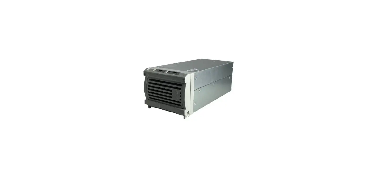
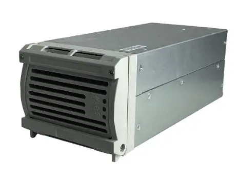
 ProEE PE-R HF Rectifier Module 24V-60A
 Electrical Specifications
 Electrical Specifications
Input Feature
| Input | Single input |
| Input Voltage Range | 90Vac to 290Vac |
| Rate input Voltage | 110Vac / 220Vac |
| Normal Input | 100Vac to 240Vac |
| Frequency Range | 45Hz-65Hz |
| Max Input Current | 10.2A±10%@176Vac/1800W |
| Surge Current | Compliant Standard:ETSI300132-3 |
| Efficiency | ≥90%@220Vac@ 220Vac 100% load |
| PF | ≥0.99@220Vac/60A |
| Leakage Current | <3.5mA@264Vac |
| Input Fuse | L Wire ,Fuse 25A |
| Max input Voltage | 310Vac |
Output Feature
Output voltage current regulation
| Output Voltage | +24Vdc |
| Output Voltage Regulation | +24±0.1Vdc |
| Output Range adjustable Range | +21Vdc~+29Vdc |
| Load sharing(50%~100% Loading) | ≤±5% |
| Line regulation | ±0.1% |
| Load regulation | ±0.5% |
| Voltage precision | ±0.6% |
| Min-current | 0A |
| Rate current | 60A |
| Peaking current | 65A |
| Tempe. coefficient(1/℃) | ≤±0.02% |
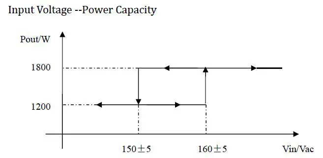
| Rate Capacity | 1800W(150Vac~290Vac) 1200W(90Vac~150Vac) |
Note: The rectifier module output current regulation and communication interruption are as follows:
- The output current of the rectifier module can be adjusted according to the current command. The adjustment range is 1A~60A.
- Communication fault more than 1 minute (Rectifier and Control monitor),A .Rectifier module output Voltage automatic recovery default Voltage 24V and limited current function not working;b.if the rectifier modules are controller by monitor and Power off, then rectifier system will power on(if the rectifier fault, it can not be turned on again)
Efficiency Figure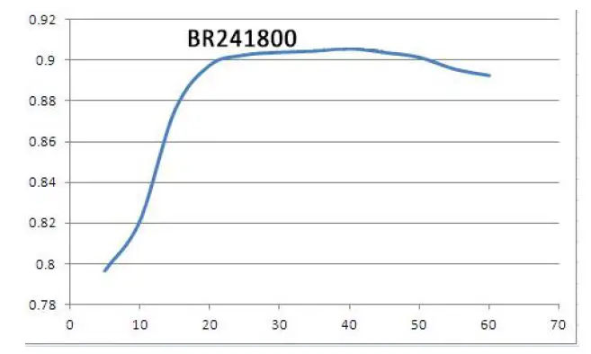
Output ripple and noise
| Output Voltage | Ripple and Noise (Peaking-Peaking) |
| +24Vdc | 200mVp-p@ 25℃,(Testing based on rate Input voltage & Output Voltage ,100% loading ) |
Note:Ripple and Noise testing:Ripple and noise Default as 20 MHz
Output dynamic response
| Voltage overshoot | Adjustment slope | Loading | Voltage overshoot |
| +24V±5% | 0.1A/uS | 25% to 50% load 50% to 75%load | ≤200us |
Note:Adjustment slope Cycle 4ms
Output Overshoot
| Output Voltage | Overshoot Voltage | |
| On | off | |
| +24V | ≤5% | ≤5% |
Note: Loading Range Minimum to maximum
Power Switch Point
| Rated Switching Point | Min-Switching Point | Max-Switching Point |
| 150Vac | 145Vac | 160Vac |
Power on output delay time
| Output Voltage | 220Vac@25℃ |
| +24V | 3S~10S |
Note: The power-on delay time is the time from AC power-on to output voltage (to 23VDC)
LED indicator
The power LED is installed on the power panel side and the output status is shown in the table below
| Indicator | LED Color | NormalStatus | Abnormal status | Abnormal Reasons |
| Power running indicators | Green | On | off | |
|
Protect indicators |
Yellow |
Off |
on | Temperature pre-alarm (working temperature more than 65 °C ,then over temperature shutdown); Sleep shutdown (the module only lights the |
| protection indicator when the system is shut down, and the module does not report alarm). | ||||
| Fault Indicator | Red | Off | on | Output Over voltage power off 、 Fan fault、Over-Temp. Power off Rectifier module inner fault。 |
Noise Voltage
| Noise Voltage | Max | Note |
| Phone noise weighting Voltage | ≤2mV | |
| broadband noise Voltage | ≤50mV | 3.4~150KHz |
| ≤20mV | 0.15~30000KHz | |
| Radio interference noise, or radio frequency noise | ≤5mV | 3.4~150KHz |
| ≤3mV | 150~200KHz | |
| ≤2mV | 200~500KHz | |
| ≤1mV | 500~30000KHz |
Rectifier module and monitor module communication function
RS485 communication mode (half-duplex, double-line) is adopted between the rectifier module and the monitoring module.
The RS485 interface in the rectifier module needs to be isolated. The RS485 power supply is +5Vdc (regulation accuracy ±5%), which is provided by the monitoring module.
The main monitoring information of the rectifier module is:
- Adjust Voltage and Current function: meet the requirements of battery floating charge and meet the adjust voltage requirements;
- Single module switch machine control;
- Alarm information:
- Mains failure: mains failure (AC input over voltage);
- Module protection: temperature pre-alarm;
- Module failure: Output over voltage shutdown, fan failure, over temperature shutdown or no output caused by internal causes of other modules; (module is in: sleep shutdown state, mains failure does not report module failure).
Protection Function
Output Limited Current Protection
| Output Voltage | Limited Current point | Note |
| +24V | 105%~110% | Limited current output |
Output short circuit Protection
| Output Voltage | Note |
| +24V | Restart after Protection |
Output Over Voltage Protection
| Output Voltage | Protection Point |
| +24V | 33±2V. (Lock) |
Note: After entering the lock protection state, you need to disconnect the AC power first, and then re-power on, the rectifier module can be re-operated.
Input Over Voltage Protection
| Input Voltage | Note |
| 310±10Vac | Output off,Self-recovery after normal voltage |
| output recovery point backlash>10V |
Note: Input overvoltage protection should be tested at 50A rated load
Input under Voltage Protection
| Input Voltage | Note |
| 80±5Vac | Output is closed. Self-recovery after normal Voltage |
| Output Recovery point backlash>5V |
Over -Temp.Protection
| Temp. | Note |
| ≤55℃ | With maximum output Capacity ability , without over-temperature protection and the module is running normally. |
| 55℃~65℃ | The module can be automatically derate to ensure long-term stable output of at least 50% of rated power |
| >65℃ | Power off,After power off,Recovery temperature difference >10℃ |
Insulation Performance
Insulation resistance
| Input & output | Testing voltage 500VDC,Insulation Resistance ≥10M (normal atmospheric pressure, normal temperature, relative humidity <90%, no condensation) |
| Input & ground | |
| Output & ground |
Isolation Voltage
| Input & output | DC Voltage 4240Vdc | 1minute ≤30mA |
| Input & ground | DC Voltage 2120Vdc | 1minute ≤30mA |
| Output & ground | DC Voltage 710Vdc | 1minute ≤30mA |
Safety standard
Power supply safety meets the following standards:
GB4943-2001
EMC
EMI
- Compliant with the the Below Standard:
Conduction Emission :
*EN55022/GB9254, CLASS A - Radiated Emission :
*EN55022/GB9254, CLASS A
EMS
The power supply shall compliance with the following Criterion:
- ESD
*GB17626.2/IEC61000-4-2- the Chassis, the parts that can be touch during normal operation: contact discharge +/-6KV; air discharge +/-8KV, Criterion B (power on test)。
- the Chassis , the parts that can be touch during normal operation: contact discharge +/-8KV; air discharge +/-10KV,Criterion R (not powered during test)。
- signal interface inner conductor: contact discharge +/- 2KV Criterion R; (power on test, no test on address line and current line)
- EFT
*GB17626.4/IEC61000-4-4 Level 3 Standard: A - SURGE
*GB17626.5/IEC61000-4-5 Level 4 Standard: B - DIP
*GB17626.11/IEC61000-4-11
Power DIP voltage drop requirement Table (220Vac)
| Drop to | Drop Phase | Drop Time | Standard |
| 0%Ut | 0°/45°/90°/135°/180°/225°/270°/315° | 10ms | B |
| 40%Ut | 0°/45°/90°/135°/180°/225°/270°/315° | 20ms | B |
| 70%Ut | 0°/45°/90°/135°/180°/225°/270°/315° | 100ms | B |
Input harmonic current
*IEC 61000-3-2 [6] CLASS A
voltage fluctuations and flicker
*IEC 61000-3-3
Pst≤1.0;P1t≤0.65;dc≤3%;dmax≤4%;d(t) more than 3% time≤200ms
lightning test
In the system application, the AC input can withstand the impact current
waveform of n more than 5 kA, 8/20us, positive and negative 5 times, each
interval of 1 minute (see standard: YD 5098-2001)
Immunity to conducted disturbances
*IEC61000-4-6 Level 3 Standard:A
Radiated interference
*IEC61000-4-3 Level 3 Standard:A
Testing Standard:
A: The power supply did not have any degradation in performance throughout the test, and it was completely the same as the specifications specified in the power supply specification.
B: During the test, the performance of the power supply is allowed to temporarily decrease, but it can be restored after the test is over.
C: A short-term loss of function is allowed, but the end of the test can be restored automatically or manually.
R: Damage to other devices other than the fuse device is not allowed during the test.
Working Environment
Ambient Temperature
- Working Temp.:-40℃to +55℃.
- Storage Temp: -40℃to +70℃.
- Transport Temp: -40℃to +70℃.
Relative Humidity
- Working RH: 5%~95% (No condensation)
- Storage RH: 5%~ 95% (No condensation)
Altitude
- working Altitude:0~4000M,based 2000m,For every 200 m increase in altitude, the temperature drops by 1℃
- Storage Altitude :0~4000M,based 2000m,For every 200 m increase in altitude, the temperature drops by 1℃
Cooling
*The rectifier module with fan, forced air cooling, air is sent out after the wind is coming forward, the fan is placed in the front, and the fan has temperature control speed regulation function.
Vibrate Tolerance
- Working environment: sinusoidal vibration: 5~9Hz: amplitude 3.5mm; 9~200Hz: acceleration 10m/s2; 3 axial direction, sweeping vibration 5 times in each direction, 1OCT/min (1 octave/min).
- Transportation environment: random vibration: 2~10Hz: 10m2/s3; 10~200Hz: 3m2/s3; 200~500Hz: 1m2/s3;3 axial, 30min in each direction.
(Reference standard: ETS300019-2)
Impact Tolerance
- Working environment: acceleration 250m / s2; pulse width 6ms; 3 axes 6 to each collision 500 times.
- Transportation environment: acceleration 400m / s2; pulse width 6ms; 3 axes 6 to each collision 500 times.
(Reference standard: ETS300019-2)
Drop
Transportation environment: drop height 1m; bottom surface 1 time.
(Reference standard: ETS300019-2)
Size
H×W×D: 83.8mm×112mm×257mm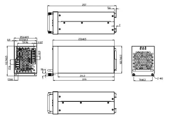
N.Weight: <4.8kg
Chassis IP Protection Level
IP20(User normal maintenance operation surface)
Transportation and storage
The product should be placed in a warehouse that is affected by dry, ventilated and non-corrosive gases with a temperature of -10 ° C to 40 ° C and a relative humidity of not more than 80%.
The product has a strong packaging when transported. The outside of the box complies with the relevant national standards and should have signs such as “careful handling” and “moisture proof”. The box containing the product is allowed to be transported by any means of transport. Direct rain and snow strikes and mechanical impacts should be avoided during transportation.
Other Requirement
| Item | Requirement | Note |
| noise | Less than 55dBa | |
| odor | not produce odor and harmful odor | |
| Components | All devices meet the de-rating | |
| Hot swap | Rectifier module for hot swap | |
| Failure isolation | After the rectifier module fails, it can be reliably separated from the system. |
MTBF
1*105h;25℃,Rate Input,100% loading.
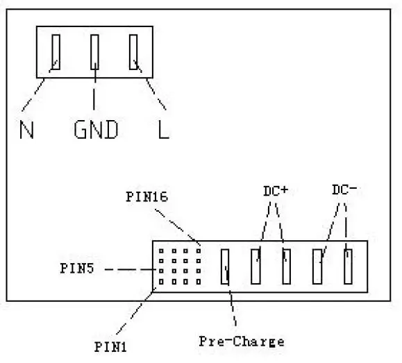
Connector PIN Definition
| Pin | Signal | Remark | Contact sequence | |
| AC input | 1 | Rectifier module AC input | L | 2 |
| 2 | Rectifier module protection Ground | PE | 1 |
| 3 | Rectifier module AC input | N | 2 | |||||
| DC output and | 1 | Rectifier module address wire | ADDRES S0 | 3 | ||||
| 2 | Rectifier module address wire | ADDRES S1 | 3 | |||||
| 3 | Rectifier module share current wire | LOADS HARE+ | 3 | |||||
| Signal | 4 | Rectifier forbidden | INHIBIT | 4 | ||||
| CURRE NT LIMIT | ||||||||
| 5 | Rectifier function | output | limited | current | 3 | |||
| 6 | Rectifier function | output | limited | current | CURRE NT LIMIT | 3 | ||
| 7 | Rectifier address wire | ADDRES S2 | 3 | |||||
| 8 | Rectifier address wire | ADDRES S3 | 3 | |||||
| 9 | Rectifier address wire | LOADS HARE- | 3 | |||||
|
DC output | 10 | RS485 Power + | +3.3V/+ 5V | 3 | ||||
| 11 | RS485 Power- | +3.3V/+ 5VGND | 3 | |||||
| 12 | Rectifier communication wire | RS485- | 3 | |||||
| and Signal | ||||||||
| 13 | Rectifier address wire | ADDRES S4 | 3 | |||||
| 14 | NC | NC | 3 | |||||
| 15 | Rectifier communication wire | RS485+ | 3 | |||||
| 16 | Address Wire GND | ADDR_G ND | 3 | |||||
| As Figure | Pre- charge | Pre-Cha rge | 1 | |||||
| As Figure | Rectifier output 48V+ | DC+ | 2 | |||||
| As Figure | Rectifier output 48V+ | DC+ | 2 | |||||
| As Figure | Rectifier output 48V- | DC- | 2 | |||||
| As Figure | Rectifier output 48V- | DC- | 1 | |||||
Block address definition:
The module internally pulls up the address line. ADDRESS0~4 can be left floating outside the module or shorted to the address line GND.
Shorting means “1”, floating means “0”, such as ADDRESS0 external and address If the line GND is shorted and the other address lines are left floating, the rectifier module address is
- The address range of the rectifier module is 0 to 31.。

- Pre-Charge pin is used to pre-charge the output capacitor inside the rectifier module when the rectifier module is hot swapped.。
Product Maintenance
- Product free maintenance time
The free maintenance level of this product is Class B, and the free maintenance period (warranty period) is 1 year. - On-site maintenance
The power module has a hot swap function, and the on-site repair mode is module replacement.


