![]()
Engineering progress
Enhancing lives*
![]()
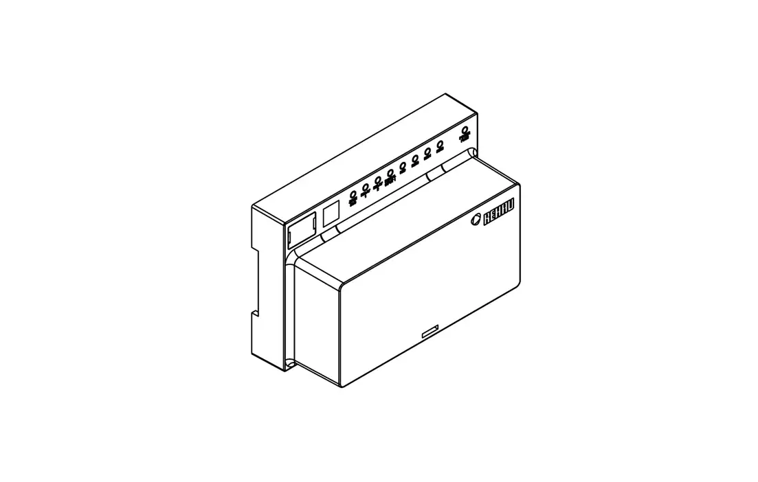
NEA SMART 2.0
U-Module 24 V
Quickinstall
Safety Instructions and Product Conformity
 Risk of life through electrical shock! The electrical installation must follow the applicable national standards and guidelines as well as any specific requirements of your local energy supplier. These instructions are intended for use by a qualified person who is holding an official certificate in one of the following professions: electrician or electronics engineer.
Always read the instructions prior to commencing the installation. Connection to the final power supply must only be carried out after the installation is complete.
Hereby, REHAU Industries SE & Co. KG declares that the Nea Smart 2.0 U-Module 24V is in compliance with EU directives 2014/35/EU, 2014/30/EU and UK regulations UK: 2016 No. 1101, 2016 No. 1091. The full text of the and UK declaration of conformity is available at the following internet address:
www.rehau.com/neasmart2
Adress
REHAU Industries SE & Co. KG
Helmut-Wagner-Str. 1
Rheniumhaus
95111 Rehau
Deutschland / Germany
Only for UK – Importer adress:
REHAU Ltd.
Hill Court
Walford
Ross-on-Wye
Herefordshire
HR9 5QN
United Kingdom
System Overview
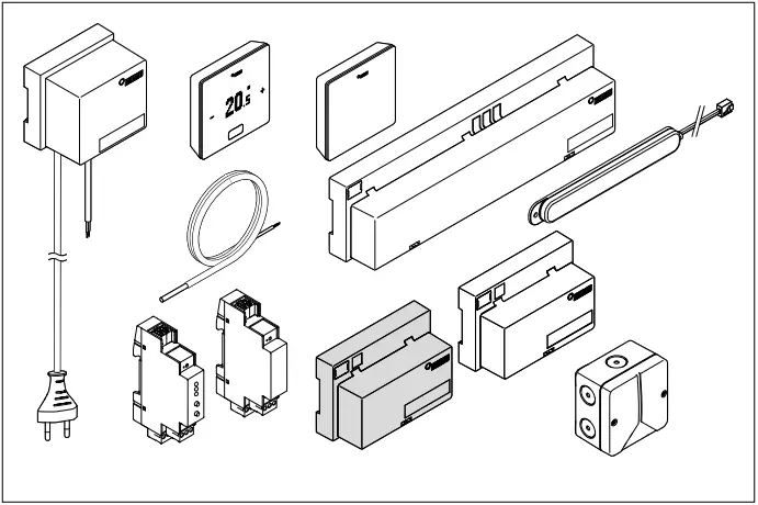
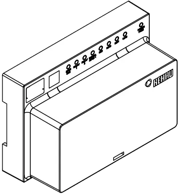
Scope of Delivery
1x 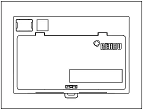
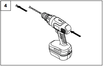
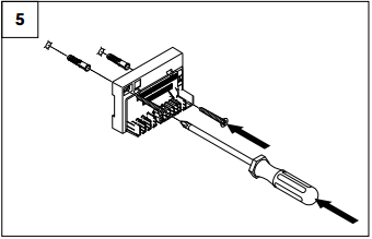
Wall Installation
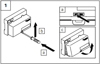
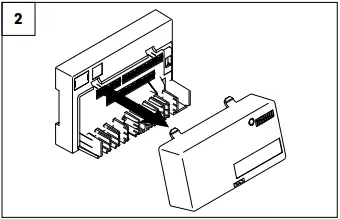
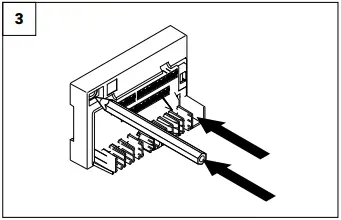
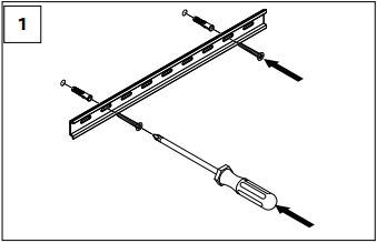
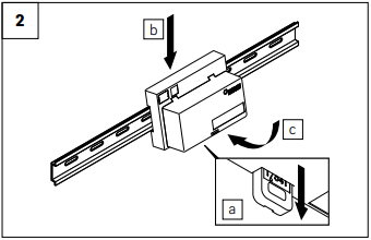
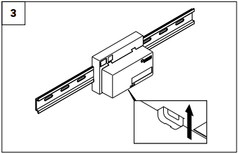
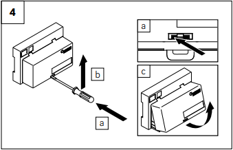
DIN Rail Installation
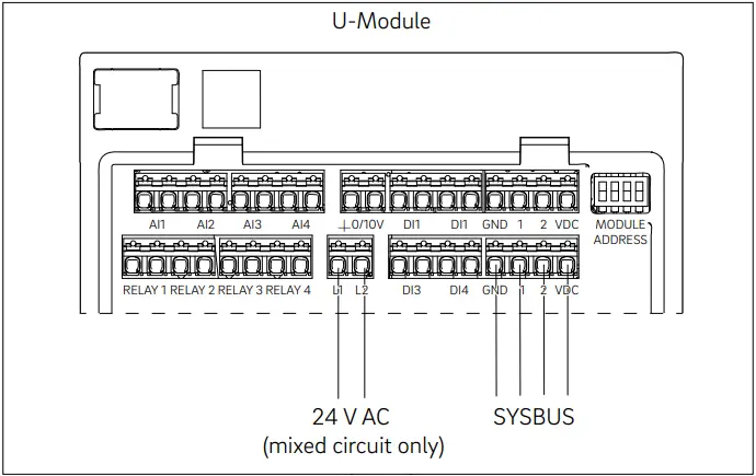
Diagrams

Electrical voltage! Danger to life!
The system is live.
- Prior to opening always disconnect from the mains and secure all components of the system in such a way that they cannot accidentally be switched on.
- Disconnect external voltages at the relay contacts and secure against unintended activation.
- Check for absence of voltage!
Electrical terminations
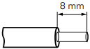 Solid cable 0,5-1,5 mm²
Multiple stranded cable 1,0-1,5 mm²
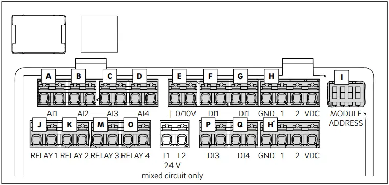
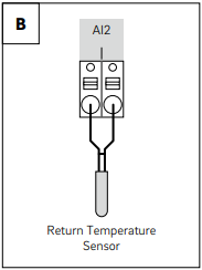
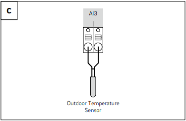
| A B C D | Analog Input 1-3: NTC 10K AI4: NTC 10K / 0…10V |
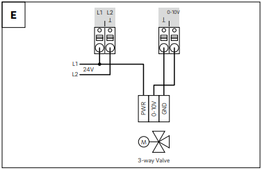
| E | Analog output 0-10 V |
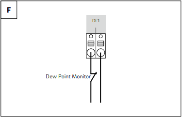
| F G P Q | Digital Input 1 – 4 |
| H | SYSBUS |
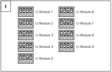
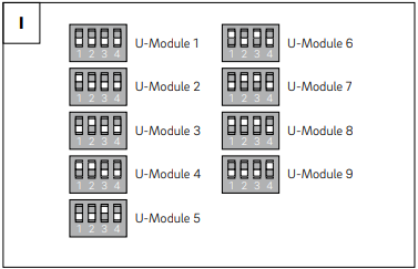
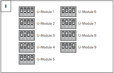
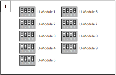
| I | DIP Switch for SYSBUS address |
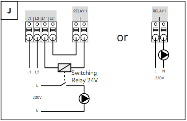
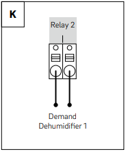
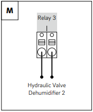
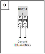
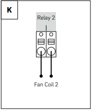
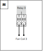
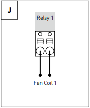
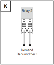
| J K M O | Relay 1 – 4 5A, Class 2 |
4 Options: Mixed Circuit / Dehumidifier / Fan Coil / Dehumidifier & Fan Coil
Mixed Circuit
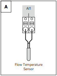

| A | Supply temperature sensor |
| B | Return temperature sensor |
| C | Outdoor temperature sensor |
| E | 0 – 10 V 3-way valve |
| H | SYSBUS |
| I | DIP switch for SYSBUS address |
| J | Pump mixed circuit |
Dehumidifier

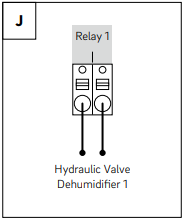
| H | SYSBUS |
| I | DIP switch for SYSBUS address |
| J | Hydraulic valve dehumidifier 1 |
| K | Demand dehumidifier 1 |
| M | Hydraulic valve dehumidifier 2 |
| O | Demand dehumidifier 2 |
Fan Coil
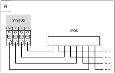

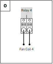
| H | SYSBUS |
| I | DIP switch for SYSBUS address |
| J K M O | Fan Coil 1-4 |
Dehumidifier & Fan Coil

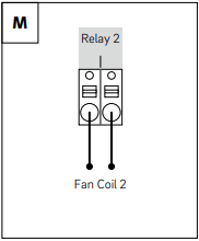
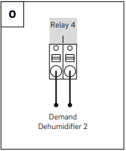
| H | SYSBUS |
| I | DIP switch for SYSBUS address |
| J | Fan Coil 1 |
| K | Demand dehumidifier 1 |
| M | Fan Coil 2 |
| O | Demand dehumidifier 2 |
Additional information


This document is protected by copyright. All rights based on this are reserved. No part of this publication may be translated, reproduced or transmitted in any form or by any similar means, electronic or mechanical, photocopying, recording or otherwise, or stored in a data retrieval system.
Our verbal and written advice with regard to usage is based on years of experience and standardised assumptions and is provided to the best of our knowledge. The intended use of REHAU products is described comprehensively in the technical product information. The latest version can be viewed at www.rehau.com/TI. We have no control over the application, use or processing of the products. Responsibility for these activities therefore remains entirely with the respective user/processor.
Where claims for liability nonetheless arise, they shall be governed exclusively according to our terms and conditions, available at www.rehau.com/conditions, insofar as nothing else has been agreed upon with REHAU in writing.
This shall also apply for all warranty claims, with the warranty applying to the consistent quality of our products in accordance with our specifications. Subject to technical changes.
954635 04.2023 © REHAU Industries SE & Co. KG, Helmut-Wagner-Str. 1, Rheniumhaus, 95111 Rehau
References
 Conditions of Sale worldwide | REHAU
-
REHAU TI Portal - Find specific technical information
-
REHAU North America
-
REHAU Group | Engineering progress – Enhancing lives
-
Conditions of Sale worldwide | REHAU
-
NEA SMART 2.0 Manager | REHAU
-
REHAU TI Portal - Find specific technical information
-
Szállítási és Fizetési Feltételek


