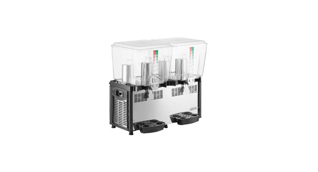
![]() 5 and 10 Gallon Bowl Refrigerated Beverage Dispensers
5 and 10 Gallon Bowl Refrigerated Beverage Dispensers
User Manual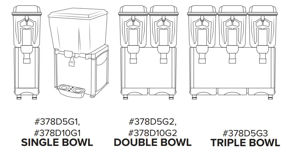
READ THOROUGHLY BEFORE OPERATION
UPDATED 05/2020 ON
SAFETY
- This instruction manual is an integral part of the machine and must be kept for any further consultation.
- This machine is a cold drink dispenser.
- This machine should be used only for the purpose for which it was designed. Any other use is inappropriate and therefore dangerous.
- The manufacturer will not be held responsible for any damage caused by improper use.
- Before installing and operating the machine read this instruction manual carefully.
- Basic safety rules:
– DO NOT touch the machine when hands or feet are wet.
– DO NOT use the machine when barefoot.
– This appliance should only be used by persons who have the knowledge, experience, and capability to operate it in a safe way.
– DO NOT allow children to play with the appliance.
– DO NOT allow the machine to be used by children or untrained persons.
– DO NOT leave the machine outdoors.
– DO NOT pull on the electrical cord to unplug the machine. - The company reserves the right to modify the construction or appearance without notice.
FEATURES & CONTROLS
TECHNICAL FEATURES
| Bowls | D5G1 | D5G2 | D5G3 | D10G1 | D10G2 |
| 1 | 2 | 3 | 1 | 2 | |
| Capacity Gas | 1 x 5 Gal | 2 x 5 Gal | 3 x 5 Gal | 1 x 10 Gal | 2 x 10 Gal |
| R134a | |||||
| Width 8.2 in | I 16.3 in | 24.2 in | 15.75 in | 30.5 in | |
| Depth 16.9 in | 16.15 in | ||||
| Height 28.9 in | 29.15 in | ||||
| Weight 45 lb | 70 lb | 95 lb | 71 lb | 126 lb | |
| Power 260W | 550W | 710W | 380W | 1100W | |
| Voltage | 120V | ||||
SERIAL PLATE
The technical features of the machine are reported on the serial plate attached on the frame.

ITEM #: 378D5G1
MFR MODEL #: JET COF 120M
SPECS: 1 x 5 GAL • 120V • 260W
GAS/Q.TY: R513 – Gr. 140
PRESSURE: HIGH – 186 PSI • LOW – 88 PSI
SERIAL #:
MAIN CONTROLS
Positioned on the right side of the machine.
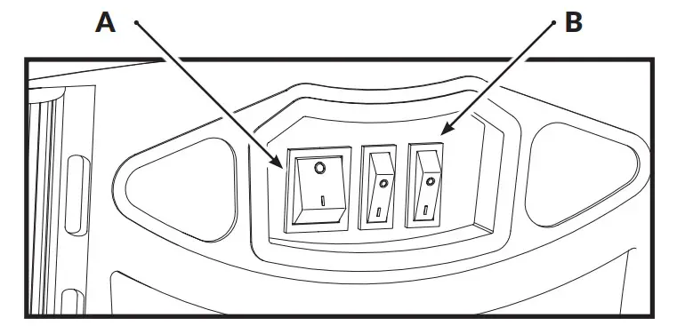 A – Main Power Switch
0: Machine is OFF
I: Machine is ON
B – Mixing System Switch(es) – One for Each Bowl
0: Mixer is OFF
I: Mixer is ON
INSTALLATION
UNPACKING
In order to prevent the oil contained in the air-tight compressor from flowing into the cooling circuit, it is necessary to always carry, store, and handle the machine in a vertical position, following the instructions found on the packaging.
If the machine was accidentally or purposely placed in a non-vertical position during transport, before operating the machine it should be kept in a straight position for approximately 30 minutes to allow the oil to flow back into the compressor.
- Remove cardboard and plastic covering.
- Make sure that the machine has not been damaged.
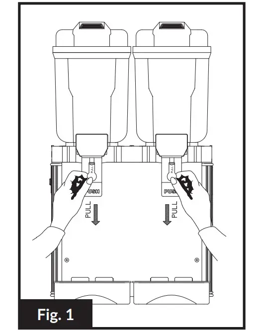
- Remove the plastic film from all the stainless steel panels.
- Before operating, remove the green plastic plug(s) from the tap(s). (Fig. 1)
![]() CAUTION
CAUTION
Dispose of packaging materials correctly.
Do not leave within reach of children.
POSITIONING
- Place the machine on a sturdy horizontal surface.
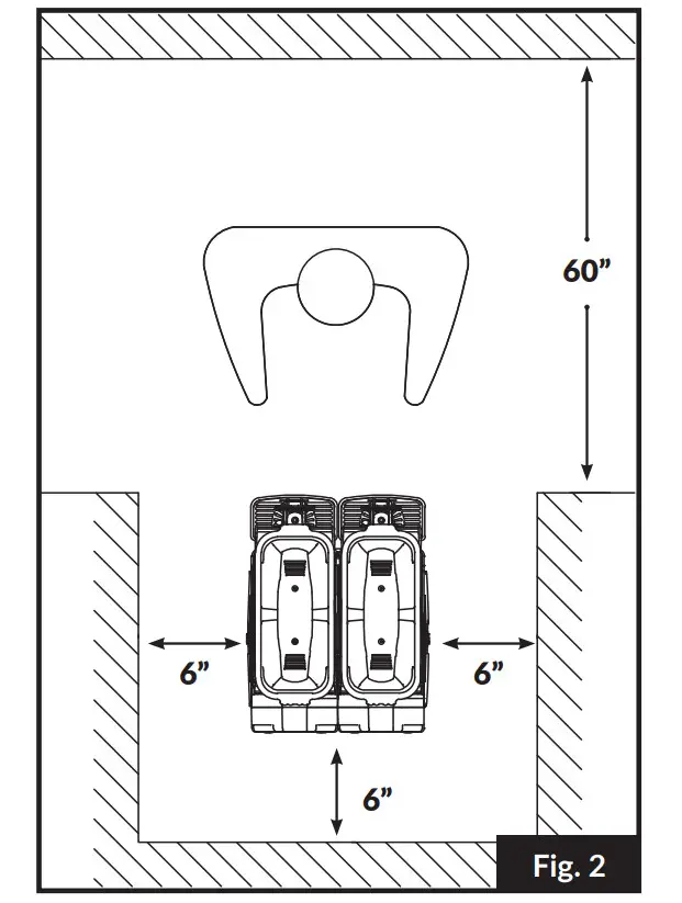
- For improved ventilation, maintain a distance of 6 in. between the unit and walls or other obstacles.
Increase the distance if the obstacles are a heating source. (Fig. 2) - Leave 60 in. of free space in front of the machine to allow for easy use and maintenance. (Fig. 2)
- Leave 10 in. of free space above the machine to allow for removal of lids. (Fig. 2)
- When the machine is in place, adjust the rubber legs to level.

ELECTRICAL CONNECTION
If in doubt, consult a specialized electrical technician.
Before inserting the plug into the electrical outlet, carefully read the following precautions:
- Make sure that the machine is properly connected to an efficient grounding system, in compliance with current safety standards;
- Make sure that the voltage is in accordance with what is indicated on the “serial number” tag applied on the chassis.
- The current available is sufficient for the maximum required by the machine;
- If needed, use only approved multiple outlets, in compliance with current safety standards
- If in doubt, consult only specialized technicians.
- By law, the machine must always be grounded.

OPERATION
![]() CAUTION
CAUTION
Before using the machine, all food contact surfaces and components must be cleaned and sanitized in accordance to the Washing & Sanitizing section of this manual.
PREPARING THE PRODUCT
Concentrate
In order to obtain a homogeneous mix, the product will need to be pre-mixed before being added to the machine. Follow the manufacturer’s recommendations for mixing.
Ready-to-Use & Pre-Mixed Concentrates
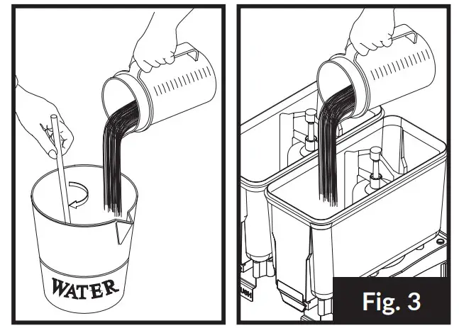
- Turn the machine OFF and unplug from power supply.
- Pour liquid into the bowl. (Fig. 3)
- DO NOT pour below the MIN Level. (3-4 L)
- DO NOT pour above the MAX Level.

COLD DRINKS
DO NOT run the pump without liquid.
CAUTION
Prepare the product separately before proceeding.
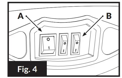
- Make sure that the main switch (A) is in the [OFF] position, and plug in the machine. (Fig. 4)
- Before starting the machine ensure that the bowls are properlyclosed with their covers.
- Turn the main switch (A) to [ON] position; the refrigerant group unit will automatically start. (Fig. 4)
- To start the mixing action, turn the mixing system switch (B) to [ON] position. There is a switch for each container. (Fig. 4)
- To pour drink out, press the drinking glass lightly against lever.

BEVERAGE TEMPERATURE REGULATOR![]() CAUTION
CAUTION
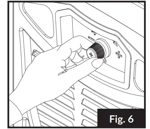
Remove power plug before adjusting temperature.
- Every dispenser has been tested and the thermostat has been set at c.a. +5°C temperature.
- To adjust this temperature, turn the thermostat knob clockwise to set a lower temperature. (Fig. 6)
- In the case of a machine with an internal thermostat, remove left or rear side panel (machine with 2 compressors).
- To disassemble the side panels, loosen the screws on the panels, pushing up then unlatching.
- To adjust the temperature turn thermostat handle clockwise to set a lower temperature.

CLEANING
CAUTION
The machine must be turned OFF and unplugged from the power source before cleaning.
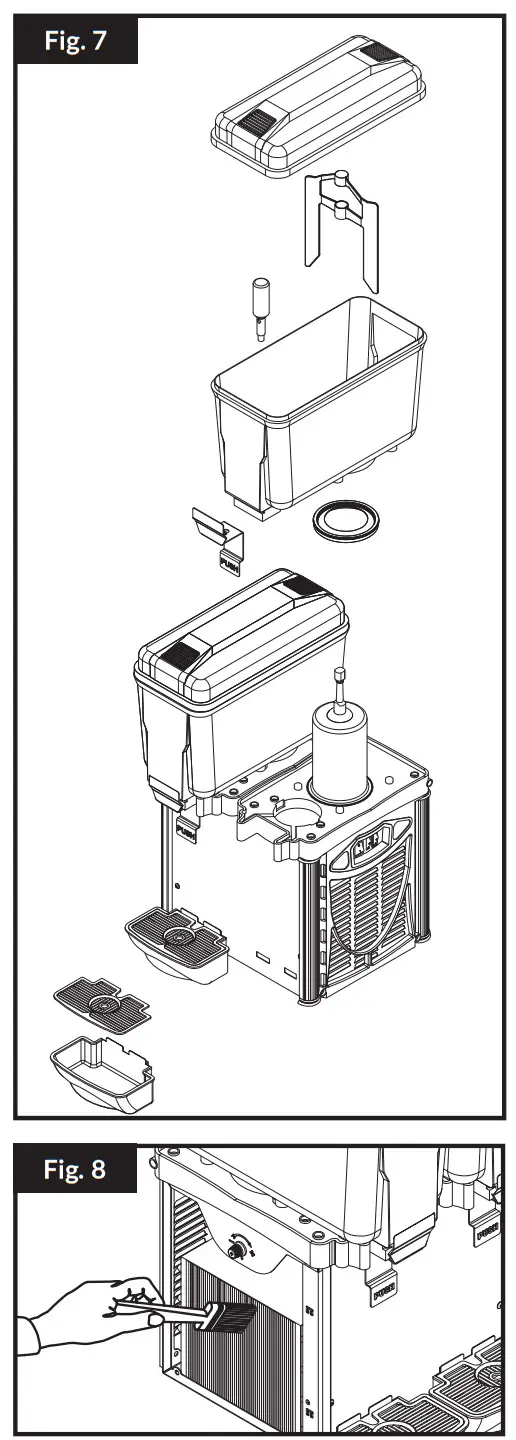
DISASSEMBLY (Fig. 7)
- Lift the lid off.
- Pull the mixer off.
Lift the container with both hands with a light, swinging motion. Should you have difficulty, it may be necessary to dampen steel refrigerator and gasket, then repeat the operation. - To remove container’s gasket, lift it from its setting.
- To disassemble the panels, unscrew the nuts on the panels, pushing up then unlatching.
- To reassemble the unit, repeat the above operations in reverse.

CLEANING
Do not use abrasive powders which might impair the container and lid’s shine
- Use neutral soap and lukewarm water to wash container, lid, mixer/pump, refrigerator, and tap.
- Rinse carefully with water in order to remove any soap residue.
- For sanitation purpose wash the parts with a solution of cold water and sodium hypochlorite (bleach) with 10 grams (1/2 spoon) for 1 liter of water ratio. Rinse with lukewarm water.
For better cleaning and sanitation, use a soft brush. - If the dispenser is out of use for a long period of time, remove the power plug and clean all parts carefully; keep the dispenser away from dust and cover it with a plastic sheet.
SERVICING
Any necessary repairs on the machine should be undertaken exclusively by an authorized repair center, using original replacement parts.
The electrical cord should not be replaced by the user.
- After disconnecting the dispenser, remove panels and clean inside parts, especially condenser fins, with a brush (Fig. 8).
- Dust reduces the performance of the machine, so clean it at least once a month.
- The dispenser does not require oiling.
DISPOSAL
When the machine is no longer of use, dispose of it properly.
Or if still operational, sell off through an authorized organiza tionor company.
TROUBLESHOOTING
![]() CAUTION
CAUTION
Problems marked with this symbol must be handled by a specialized technician.
PROBLEM | CAUSE | SOLUTION |
| The machine does not turn ON | The Main Switch is not set to I | Set the Main Switch to I |
| The machine is not plugged in | Plug the machine into the outlet | |
| Electric cable defective | Replace the electric cable | |
| The Main Switch is defective | Replace the switch | |
| The machine is not cooling | Compressor does not start | See Compressor does not start section below |
| Gas leak into the cooling circuit | Find leak, filter it out & re-charge cooling circuit | |
| Condenser is clogged | Clean the condenser (see Fig. 8) | |
| Fan motor is burnt out | Replace the fan motor | |
| Lack of air flow | Increase the distance between the machine and other obstacles/heating sources (see Fig. 2) | |
| Compressor does not start | Main switch is broken | Replace main switch |
| Compressor protector is broken | Replace compressor protector | |
| Compressor relay is broken | Replace compressor relay | |
| Compressor motor is broken | Replace motor | |
| One bowl is not cooling | Gas leak into the cooling circuit | Find leak, filter it out & re-charge cooling circuit |
| Condenser is clogged | Clean the condenser (see Fig. 8) | |
| Lack of air flow | Increase the distance between the machine and other obstacles/ heating sources (see Fig. 2) | |
| Tube of the cooling circuit is clogged | Cut the tube, eliminate clog, re-charge the cooling circuit | |
| Filter is clogged | Replace the filter | |
| Stirring paddles not working | The gearbox is broken | Replace the gearbox, taking care to assemble it in the correct position |
| The gearbox switch is broken | Replace the gearbox switch | |
| The pump is not working | The pump motor is broken | Replace the pump motor |
| The pump switch is broken | Replace the pump switch |
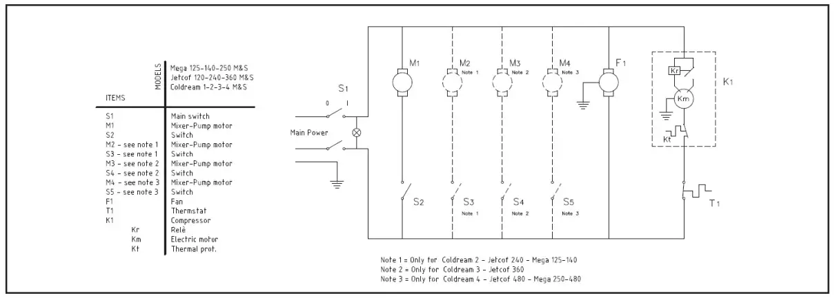
ELECTRICAL DIAGRAM – D5G1/2/3
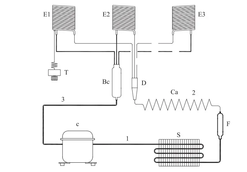
| c | Compressor |
| S | Exchanger |
| F | Fan motor |
| Bc | Boiler collector |
| E 1,2,3 | Evaporator |
| D | Distributor |
| Ca | Capillary |
| 1 | Drain Line |
| 2 | Liquid Line |
| 3 | Suction Line |
| T | Thermostat |
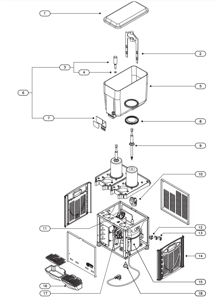
PARTS DIAGRAM – D5G1/2/3
| NO. | CODE | DESCRIPTION |
| 1 | 169 | Lid |
| 2 | 180 | Mixer Paddle |
| 3 | 226 | S/S Piston |
| 4 | 153 | O-R for Stainless Steel Tap |
| 5 | 161 | Bowl |
| 6 | 215 | Stainless Steel Tap Assembly |
| 7 | 369 | Push Lever |
| 8 | 151 | Bowl Gasket |
| 9 | 184 | Mixer Guiding Shaft |
| 10 | 297 | Gearbox 110V |
| 298 | Gearbox 220V | |
| 11 | 64 | Thermostat |
| 12 | 57 | Red Switch |
| 13 | 56 | Black Switch |
| 14 | 0193,00 | Side Panel Grey |
| 0193,01 | Side Panel Red | |
| 0193,02 | Side Panel Blue | |
| 15 | 85 | Compressor 220V |
| 86 | Compressor 110V | |
| 0067,02 | Compressor 220V | |
| 0067,03 | Compressor 110V | |
| 82 | Compressor 220V/50 | |
| 83 | Compressor 220V/60 | |
| 84 | Compressor 110V | |
| 16 | 666 | Drip Tray |
| 17 | 182 | Fan Motor 220V |
| 68 | Fan Motor 110V | |
| 833 | Fan Motor 220V | |
| 834 | Fan Motor 110V | |
| 835 | Fan Motor 220V | |
| 836 | Fan Motor 110V | |
| 18 | 150 | Rubber Leg |
READ THOROUGHLY BEFORE OPERATION
UPDATED 07/2022


