![]() IL01203004Z
IL01203004Z
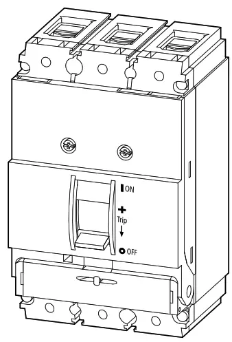
NZMB Thermal Magnetic Circuit Breaker
Instruction Manual
 NZMB(C)(N)(S)(H)1(-4)-A(M)(S)…
NZMB(N)1-A(AF)…-NA
NZMB(N)1-S…-CNA
(P)N1-… NS1-…-NA
NZMB Thermal Magnetic Circuit Breaker
Electric current! Danger to life!![]() Installation, commissioning and maintenance work must be carried out by qualified personnel only.
Installation, commissioning and maintenance work must be carried out by qualified personnel only.
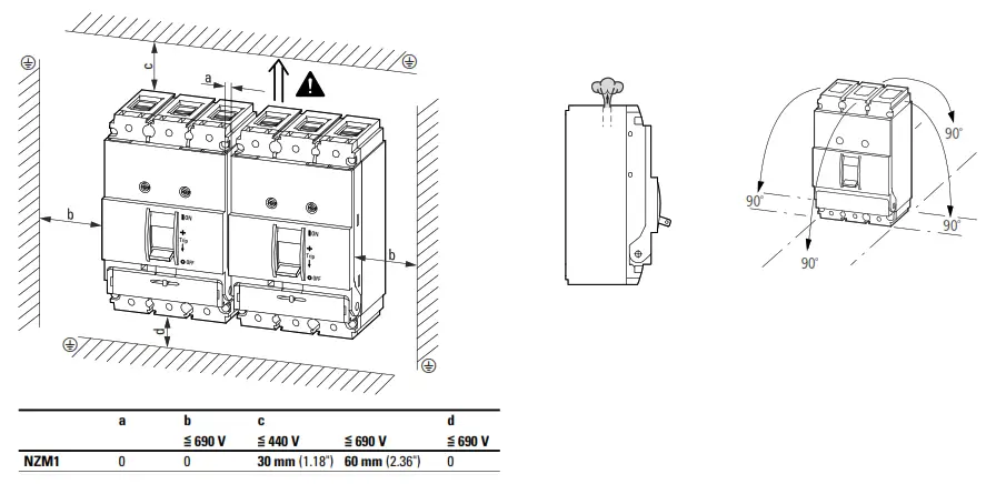
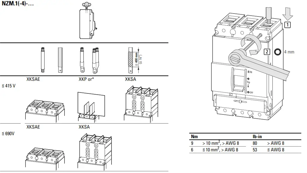
Minimum clearance/direction of blow-out
Terminals
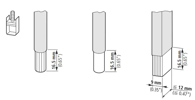
| 1 x 10 – 70 mm² | 1 x 10 – 16mm² | ≧ 2 x 9 x 0.8 mm (≧ 2 x 0.35“ x 0.03“) |
| 2 x 6 – 25 mm² | 2 x 6 – 16 mm² | |
| 1 x AWG 4 – AWG 2/0 | 1 x AWG 12 – AWG 6 | |
| 2 x AWG 10 – AWG 4 | 2 x AWG 10 – AWG 6 |
UL/CSA = Cu only, Ampacity per 75° C Table.
Wiring terminations circuit breaker type NZM…1…-NA (CNA)
Wiring terminations molded case switch type N(S)1…-NA
| Connector type | Wire size | Wire 75° C | Max. A-Rating | Tightening-Torque |
| 1)NZM1-XKC | 1 x AWG 2/0 – 12 2xAWG 4 -10 | Cu only | 125 | 9 Nm (80 lb-in) 6 Nm (53 lb-in) (AWG 8 – 12) |
| NZM1-XKA | 1 x AWG 3/0 – 6 | Cu only | 125 | 15 Nm (133 lb-in) |
| NZM1-XKS | 1 x AWG 2/0 – 12 2xAWG 4 -10 | Cu only | 125 | 9 Nm (80 lb-in) |
| 2)Integrated Auxiliary Terminal | 1 x AWG 12 – 18 | Cu only | 1.2 Nm (11 lb-in) |
- Connector Type NZM1-XKC supplied standard on all NZM1 circuit breakers and switches.
- Integrated Auxiliary Terminal on Connector Type NZM1-XKA only.
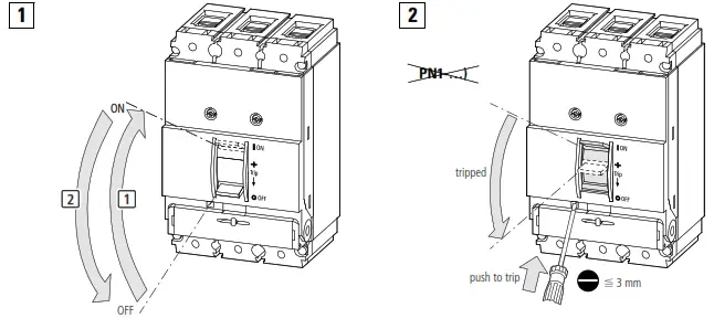
Settings
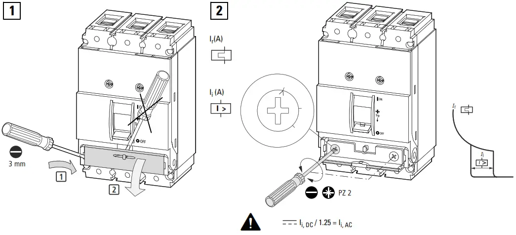
![]() Note: On certain models with UL/CSA labeling the thermal trip setting is fixed and only the magnetic trip (instantaneous) setting is adjustable.
Note: On certain models with UL/CSA labeling the thermal trip setting is fixed and only the magnetic trip (instantaneous) setting is adjustable.
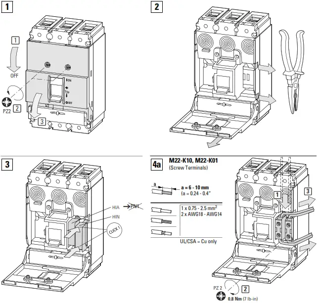
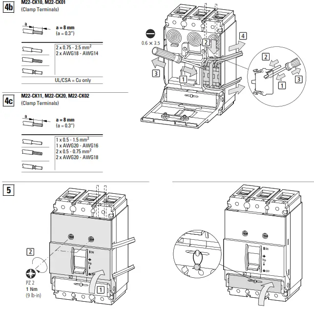
Accessories
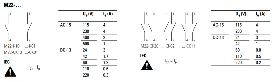
Notes on mounting and wiring Auxiliary Switches for UL/CSA labeled models:
- M22-K(10)(01) have screw terminals. M22-CK(10)(01)(20)(02)(11) have clamp terminals.
- Switch modules are snapped into place at the locations shown in the diagrams that follow.
- Switches will function as either “standard” or “trip/alarm” contacts depending on their mounting location.
- Location “HIN” refers to standard operation. Location “HIA” refers to “trip/alarm” operation.
- Follow the numbering and wiring scheme provided above depending on the contact location and function. (N.O. or N.C.)
- Permissible contact configuration: 1 HIA and/or 2 HIN.
![]() Note:
Note:
After mounting of the M22… switch is complete, check off the appropriate box on the auxiliary switch label provided on the side of the breaker or switch.
-NA -CNA (UL/CSA)
| Ith = Ie | |
| Ue (V) | Ie (A) |
| 600 AC | 5 A |
| 250 DC | 1 A |
Pilot Duty Ratings: B 600, Q 300 Above 300 V AC Same polarity
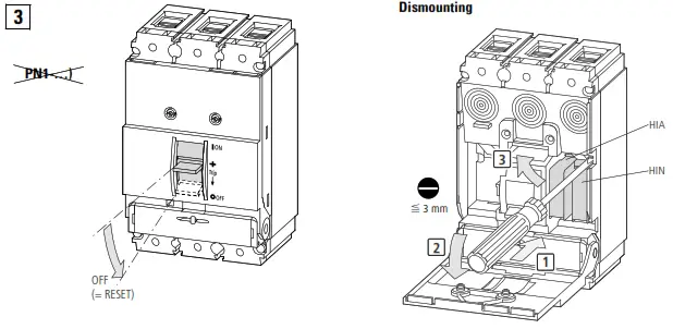
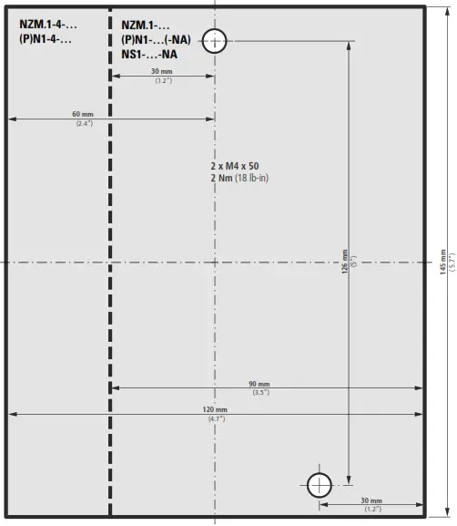
Test
![]() Eaton Electric Ltd., P.O. Box 554, Abbey Park, Southampton Road, Titchfield, PO14 4QA, United Kingdom
Eaton Electric Ltd., P.O. Box 554, Abbey Park, Southampton Road, Titchfield, PO14 4QA, United Kingdom
USA:
Eaton.com/eatoncare
+1 877-386-2273
Eaton.com/aftersales
07/22 IL01203004Z
Eaton.com/recycling
© 2002 Eaton Industries GmbH


