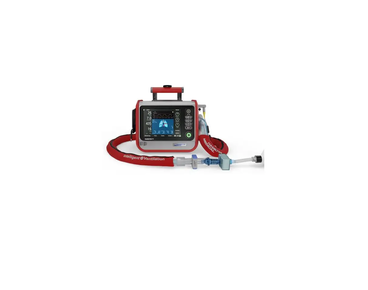
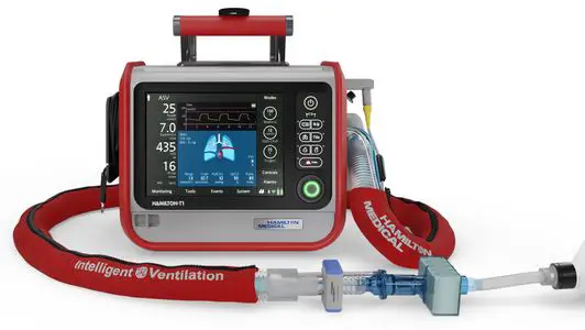
HAMILTON MEDICAL T1 Ventilator
© 2021 Hamilton Medical AG. All rights reserved. Printed in Switzerland.
No part of this publication may be reproduced, stored in a database or retrieval system, or transmitted in any form or by any means, electronic, mechanical, or by photocopying, recording, or otherwise, without prior written permission of Hamilton Medical AG.
This document may be revised, replaced, or made obsolete by other documents by Hamilton Medical AG at any time and without notice. Ensure that you have the most current applicable version of this document; if in doubt, contact the technical support department of Hamilton Medical AG, Switzerland. While the information set forth herein is believed to be accurate, it is not a substitute for the exercise of professional judgment.
Nothing in this document shall limit or restrict in any way Hamilton Medical AG’s right to revise or otherwise change or modify the equipment (including its software) described herein, without notice. In the absence of an express, written agreement to the contrary, Hamilton Medical AG has no obligation to furnish any such revisions, changes, or modifications to the owner or user of the equipment (including software) described herein.
The equipment must be operated, serviced, or upgraded only by trained professionals. Hamilton Medical AG’s sole responsibility with respect to the equipment and its use is as stated in the limited warranty provided in the operator’s manual.
Hamilton Medical AG shall not be liable for any loss, cost, expense, inconvenience, or damage that may arise out of misuse of the product, or if non-Hamilton Medical AG parts were used when replacing parts, or if serial numbers were amended, deleted, or removed.
If returning parts to Hamilton Medical AG, be sure to use the standard Hamilton Medical returned goods authorization (RGA) procedure. Disposal of parts shall follow all local, state, and federal regulation with respect to environmental protection.
Product and company names mentioned herein may be the trademarks and/or registered trademarks of their respective owners.
Hamilton Medical AG will make available, on request, circuit diagrams, component parts lists, descriptions, calibration instructions, or other information that will assist appropriately trained personnel to repair those parts of the equipment designated by Hamilton Medical AG to be repairable.
Manufacturer
Hamilton Medical AG
Via Crusch 8
CH-7402 Bonaduz Switzerland
Phone: (+41) 58 610 10 20
[email protected] www.hamilton-medical.com
Document history
Table 1-1. Document history
| Document version No. | Amendment | Date of issue |
| 00 | First release | June 2011 |
| 01 | Minor text corrections | October 2011 |
| 02 | Content updated | — |
| 03 | New security clamp and power cord CN included | January 2014 |
| 04 | Content updated | June 2014 |
| 05 | – Feature icons added – Illustrations updated | February 2016 |
|
06 | – New template – Text and illustrations updated due to new hardware and software specifications |
September 2021 |
Notes, cautions and warnings
Safety messages are displayed as follows:
WARNING
A WARNING alerts the user to the possibility of injury, death, or other serious adverse reactions associated with the use or misuse of the device.
CAUTION
A CAUTION alerts the user to the possibility of a problem with the device associated with its use or misuse, such as device malfunction, device failure, damage to the device, or damage to other property.
NOTICE
A NOTICE emphasizes information of particular importance.
For additional information, see the System Overview Chapter of the HAMILTON-T1 Operator‘s Manual (PN 10101879).
Introduction
This guide describes how to set up the HAMILTON-T1 ventilator and prepare it for operation. This includes instructions to install all its main components and optional accessories.
If you have questions, contact your Hamilton Medical technical support representative or write to [email protected].
NOTICE
Depending on the ordered configuration some parts may not be available or already be installed to the ventilator.
Installation requirements
Service engineers/technicians responsible for the installation must comply or fulfill the following requirements:
- Only trained service engineers authorized by Hamilton Medical are allowed to service, maintain, install, and replace parts/components of the ventilator.
- Always return defective parts, components, or assemblies to Hamilton Medical AG, Switzerland, with a completed Return Good Authorization (RGA) request.
Delivered parts and accessories
Required parts
Table 5-1. Required parts
| Graphic | Part description | Part number |
 | HAMILTON-T1 ventilator | 161005 161006 1610060 |
 | HAMILTON-T1 gray ventilator unit for armed forces | 161009 1610090 |
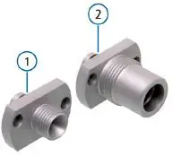 | High-pressure oxygen connector (including nut and nipple connector) | ① 160470 DISS or ② 160471 NIST |
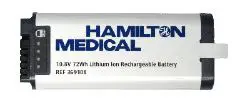 | Battery | 369108 |
 | Battery cap with screws | MSP161173 |
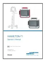 | Operator’s Manual | 161030 English 161032 Spanish 161031 German 161033 French 161037 Italian 161034 Russian 161035 Chinese 161036 Portuguese |
Basic accessories
Table 5-2. Basic accessories
| Graphic | Part description | Part number |
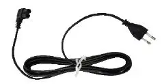 | Power cord | 355198 USA 355199 GBR 355200 EU 355308 CHN |
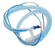 | Single use coaxial breathing set,1.80 m with flow sensor | 2600871 |
| 1 Not delivered tcountries | ||
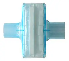 | Single use HMEF inspiratory filter | 2799631 Adult or 2792041 Neonatal |
| 1 Not delivered to all countries | ||
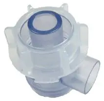 | Single use expiratory valve set | 161154 Adult or 161188 Neonatal |
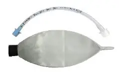 | Demonstration lung | 151815 Adult or 282494 Neonatal |
Optional accessories
Table 5-3. Optional accessories
| Graphic | Part description | Part number |
 | O2 sensor | 10110473 |
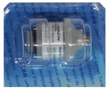 | O2 sensor | 396200 |
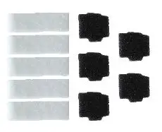 | Filter set | 161275 |
 | Feature icons positioning guide | 161976 |
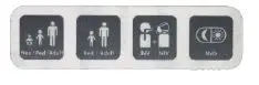 | Feature icons | 161737 |
 | INTELLiVENT-ASV icon positioning guide | 101056611 |
| 1 Not delivered to all countries | ||

| INTELLiVENT-ASV icon | 1617461 |
| 1 Not delivered to all countries |
| Graphic | Part description | Part number |
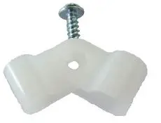 | Cable clamp | 361061 GBR and EU or 361097 USA and CHN |
 | Reusable protective sleeve, short version | 161435 Red or 161136 Black |
Packaging
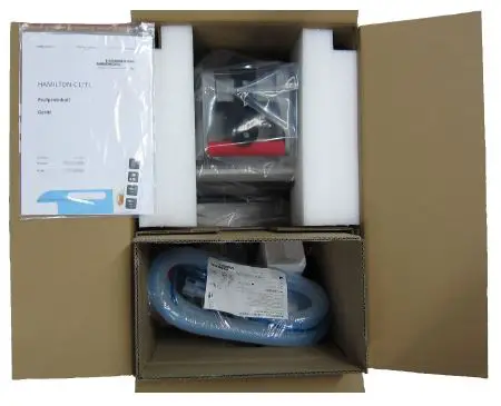
Figure 6-1. Packaging overview
NOTICE
- Store the original packaging, including the protective material for later use. This will protect the equipment if you have to move it.
- Breathing set not included for all countries.
Installing the oxygen connector
NOTICE
For 1610060 and 1610090 devices, the DISS or NIST oxygen connector is preassembled during production.
- Remove the yellow protective cap (1) from the high-pressure oxygen inlet.
- Use a Torx TX 10 screwdriver to remove the two screws (2).
Figure 7-1. Removing the yellow protective cap and screws from the high-pressure oxygen inlet
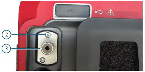
- Position the DISS or NIST connector (3) in its housing and push it in position.
CAUTION- Make sure the two holes for the screws in the connector (3) matches the ones in the ventilator. Use the figure below as a reference.
- Make sure the connector (3) is correctly placed and fully inserted in its housing.
For additional information, see the Oxygen Connectors Set Installation Guide (PN 612219).
- Install the two screws (2). Use a Torx TX 10 screwdriver to tighten the two screws (2).
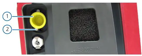
Figure 7-2. Installing the DISS/NIST connector
Installing the O2 sensor
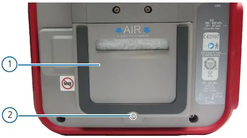
- Use a size 2 slotted screwdriver to remove the screw (2).
- Tilt out and remove the filter cover (1).

- Check the presence of the O2 sensor (5).
CAUTION
Do not switch on the ventilator if the O2 sensor (5) is not correctly installed. Contact Hamilton Medical for assistance.
NOTICE- If the O2 sensor (5) is already mounted to the ventilator, remove the cell plug (4) and check that the O2 sensor (5) is tightly mounted into its housing. In case of movement, tighten the O2 sensor (5) by turning it clockwise.
- Afterwards, reconnect the cell plug (4), reinstall the filter cover (2) and secure it in position with the screw (1).
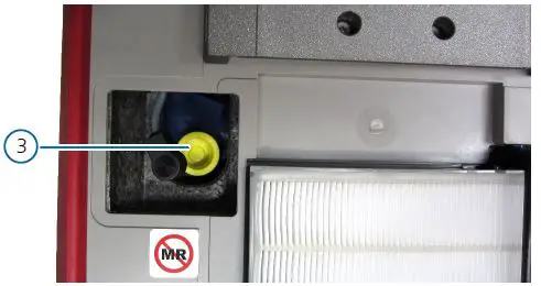
- Remove the yellow protective cap (3) from the O2 sensor housing.
Figure 8-2. Removing the yellow protective cap from the O2 sensor housing
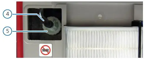
- Align the O2 sensor (5) with the screw thread in the housing. Then, turn the O2 sensor (5) clockwise to tighten it.
- Insert the cell plug (4) into the O2 sensor (5).
Figure 8-3. Installing the O2 sensor
- Attach the air filter cover (1) removed earlier. Reinstall the screw (2) to secure the filter cover (1) to the ventilator.
Connecting the power sources
Before proceeding with the installation, see the Connecting to a power source Chapter of the HAMILTON-T1 Operator‘s Manual (PN 10101879).
Installing the battery
NOTICE
For 1610060 and 1610090 devices, the battery is preassembled during production.
- The HAMILTON-T1 ventilator is a class II device according to IEC 60601-1. Therefore, it does not require any protective earth grounding.
- Before installing the ventilator, always check the reliability of the chosen power source (AC or DC).
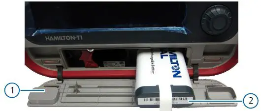
- Carefully open the battery door (1) on the front of the ventilator.
- Insert the battery (2) in the compartment on the right.
NOTICE- As soon as the battery (2) is fully inserted, the ventilator will turn on automatically.
- Wait until all security checks are carried out and, when the main screen is displayed, turn the ventilator off by pressing and holding for three seconds the power button.
- If a second battery is available, insert it in the compartment on the left.
Figure 9-1. Installing the primary battery
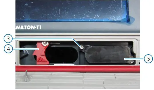
- Place the battery cap (5) to close the compartment on the right with the previously installed primary battery (2) inside.
- Use a Torx TX 10 screwdriver to tighten the two screws (3) provided.
NOTICE
Make sure the battery retaining lock (4) for the second battery is properly closed, even if the second battery is not installed. An open battery retain lock (4) will not allow the battery door (1) to close. - Carefully close the battery door (1).
Figure 9-2. Mounting the battery cap
Connecting the AC power cord
NOTICE
- The primary power supply for the HAMILTON-T1 ventilator is AC between 100 and 240 V and between 50 and 60 Hz.
- Before installing the ventilator, check the location of the AC plugs and make sure to have enough free space to easily disconnect the power supply whenever needed.
- To avoid unintentional disconnections, always secure the AC power cord with the provided cable clamp
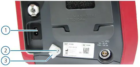
- Use a Torx TX 10 screwdriver to remove the screw (2) and release the cable clamps (3).
- Connect the AC power cord to the AC socket (1) on the ventilator.
Figure 9-3. Removing the cable clamps
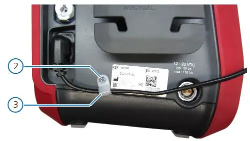
- Choose between the two cable clamps (3), the one matching the AC power cord size. Use the small clamp for GBR and EU power cords and the big clamp for USA and CHN power cords.
- Position the chosen cable clamp (3) on the AC power cord near the provided hole.
- Use a Torx TX 10 screwdriver to reinstall the screw (2) and fix the cable clamp to the ventilator.
Figure 9-4. Installing the AC power cord
- Connect the other end of the AC power cable to a suitable AC power supply.
- After switching on the ventilator, the power symbol (4) will be displayed in the bottom right corner of the screen.
Figure 9-5. Power and battery symbols on the display
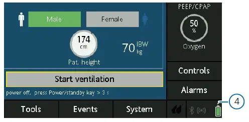
NOTICE
If the second battery is installed, a second battery icon is also displayed on the screen.
Attaching the icons
Feature icons
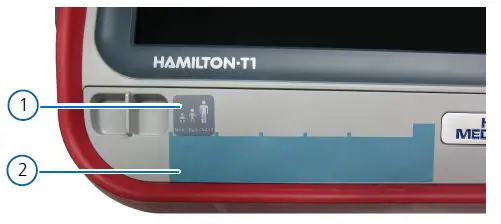
- Attach the feature icons positioning guide (2) to the front left corner of the ventilator.
- Attach the required feature icons (1) to the ventilator in the spaces marked by the feature icons positioning guide (2).
- Remove and discard the feature icons positioning guide (2).
Figure 10-1. Attaching the feature icons
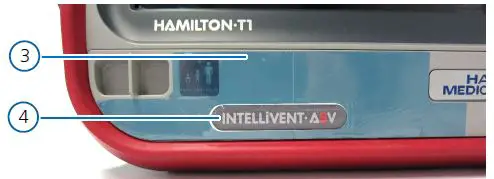
INTELLiVENT-ASV icon
- Attach the INTELLiVENT-ASV icon positioning guide (3) to the front left corner of the ventilator.
- Attach the INTELLiVENT-ASV icon (4) to the ventilator in the space marked by the INTELLiVENT-ASV icon positioning guide (3).
- Remove and discard the INTELLiVENT-ASV icon positioning guide (3).
Figure 10-2. Attaching the INTELLiVENT-ASV icon
Testing and acceptance
Device information
Table 11-1. Device information
| HAMILTON-T1 | |
| Ventilator serial number: | SN |
| Inventory number: | |
| Software version: | . . |
| Name of hospital and location: | |
| Name of distributor and country: | |
| Name of installer: | |
| Date (YYYY/MM/DD) | / / |
Component installation
Table 11-2. Component installation checks
| Task | Yes | No | Not applicable | HAMILTON-T1 manual reference |
|
DSS / NIST connector correctly installed? |
|
|
| See the Installing the oxygen connector Chapter of the Installation guide (PN 624412). |
| O2 sensor correctly installed? |
|
|
| See the Installing the O2 sensor Chapter of the Installation guide. |
| Primary battery correctly installed? | See the Installing the battery Chapter of the Installation guide. | |||
| Secondary battery correctly installed? | ||||
| AC power cord correctly installed? |
|
|
| See the Connecting the AC power cord Chapter of the Installation guide. |
| Feature icons correctly installed? | See the Attaching the icons Chapter of the Installation guide. | |||
| INTELLiVENT-ASV icon correctly installed? |
General checks
Table 11-3. General checks
| Task | Yes | No | Not applicable | HAMILTON-T1 manual reference |
| Connect the ventilator to an AC power supply and an oxygen supply. Assemble the patient breathing circuit.
Is the breathing circuit correctly assembled? |
|
|
| See the Preparing the ventilator Chapter of the Operator’s Manual (PN 10101879). |
| Switch on the power. When the ventilator is switched on the buzzer sounds briefly and the red alarm lamp flashes. After the self-test is passed the alarm lamp flashes again. |
|
|
| See the Turning the ventilator on and off Chapter of the Operator’s Manual. |
| Use the configuration setting to choose the language.
Is the desired language set? |
|
|
| See the Selecting the default language Chapter of the Operator’s Manual. |
| Set the date and time correctly.
Are the correct date and time set? |
|
|
| See the Setting date and time Chapter of the Operator’s Manual. |
| Perform the electrical safety tests. Document the measured values.
Are the measured values ok? |
|
|
| See the Electrical safety Chapter of the Service Manual (PN 624393). |
| Perform the leak test.
Is the leak test passed? |
|
|
| See the Performing the breathing circuit Leak test Chapter of the Operator’s Manual. |
| Perform the flow sensor calibration test.
Is the flow sensor calibration test passed? |
|
|
| See the Calibrating the adult/pediatric flow sensor Chapter of the Operator’s Manual. |
| Perform the O2 sensor calibration test.
Is the O2 sensor calibration test passed? |
|
|
| See the Calibrating the O2 sensor Chapter of the Operator’s Manual. |
| Generate an alarm situation.
Is the corresponding alarm message correctly displayed? |
|
|
|
See the Responding to alarms Chapter of the Operator’s Manual. |
| Resolve the alarm situation (e.g. re-connect the mains power).
Is the alarm reset? |
|
|
|
| Task | Yes | No | Not applicable | HAMILTON-T1 manual reference |
| Update the Hamilton Connect Module (HCM) firmware.
Is the HCM firmware correctly updated? |
|
|
| See the Hamilton Connect Communication Guide (PN 10102528). |
| Configure the HCM.
Is the HCM correctly configured? |
|
|
| See the Hamilton Connect Configuration Tool User Guide (PN 10110032) |
| Install the Hamilton Connect App.
Is the Hamilton Connect App correctly installed? |
|
|
| |
| Connect the ventilator to the Hamilton Connect App.
Is the ventilator correctly connected to the Hamilton Connect App? |
|
|
| See the Hamilton Connect App Instructions for use (PN 10103324) |
NOTICE
- If the HAMILTON-T1 ventilator does not pass the initial installation tests and checks, contact your local Hamilton Medical representative or Hamilton Medical’s technical support for assistance.
- After you have completed the Initial Installation Testing and Acceptance Report for the HAMILTON-T1 ventilator, please send a copy of the report to your local Hamilton Medical representative or Hamilton Medical ([email protected]), and save/archive the original report for your records.
Remarks:
Date (YYYY/MM/DD)
__ __ __ __ / __ __ / __ __
Signature ____________________
More information and free software simulation: www.hamilton-medical.com
Hamilton Medical AG
Via Crusch 8, 7402 Bonaduz, Switzerland
+41 58 610 10 20
[email protected]
www.hamilton-medical.com
Distributor USA:
Hamilton Medical, Inc.
4990 Energy Way, Reno, NV 89520
+41 58 610 10 20
[email protected]
www.hamilton-medical.com


