![]() Operating Instructions & Parts Manual
Operating Instructions & Parts Manual
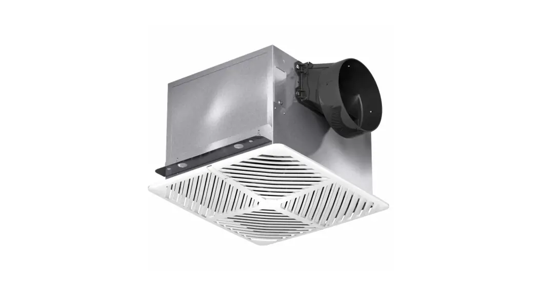
Insulated Ventilators
Models 60RG34, 60RG35, 60RG36, 60RG39, 60RG40, 60RG41, 60RG42,
60RG43, 5AE75, 60KU32, 5AE77, 60RG45, 60RG46, 5AE80,
60KU34, 6WZN1, 6WZN2, 60KU31,
60KU33, 60KU42, 60KU43, 60KU44
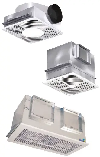

60RG34 Insulated Ventilators
PLEASE READ AND SAVE THESE INSTRUCTIONS. READ CAREFULLY BEFORE ATTEMPTING TO ASSEMBLE, INSTALL, OPERATE OR MAINTAIN THE PRODUCT DESCRIBED. PROTECT YOURSELF AND OTHERS BY OBSERVING ALL SAFETY INFORMATION. FAILURE TO COMPLY WITH NSTRUCTIONS COULD RESULT IN PERSONAL INJURY AND/OR PROPERTY DAMAGE! RETAIN INSTRUCTIONS FOR FUTURE REFERENCE. PLEASE REFER TO BACK COVER FOR INFORMATION REGARDING DAYTON’S WARRANTY AND OTHER IMPORTANT INFORMATION.
Model #: ___________________
Serial #: ___________________
Purch. Date: _______________
BEFORE YOU BEGIN
![]() WARNING
WARNING
Installation, troubleshooting and parts replacement are tobe performed only by qualified personnel in accordance with all applicable codes and standards, including fire-rated construction.
Electrical Requirements:![]() WARNING
WARNING![]() Install all wiring, protection and grounding in accordance with the U.S. National Electrical Code (NEC) and all local requirements. Follow all local electrical and safety codes, as well as the U.S.
Install all wiring, protection and grounding in accordance with the U.S. National Electrical Code (NEC) and all local requirements. Follow all local electrical and safety codes, as well as the U.S.
National Electrical Code (NEC) and the Occupational Safety and Health Act (OSHA).![]() Tools Needed:
Tools Needed:
- Lock-Out Tag-Out
- Phillips Screwdriver
- Drill
- Sheet Metal Screws
Recommended Accessories:
- Speed Control (48C172, 48C173, 43Y140, 35YV92-35YV94)
- Non-Lighted (3DPF7-3DPF8) Ceiling Radiation Damper
- 6″ Round Duct Connector (6WZP2)
- 8″ Round Duct Connector (6WZP3)
UNPACKING
 Contents:
- Dayton ® Insulated Ventilator (1)
- Mounting Brackets with Hardware (2)
- Operating Instructions and Parts Manual (1)
 Inspect:
- After unpacking unit, inspect carefully for any damage that may have occurred during transit. Check for loose, missing, or damaged parts. Shipping damage claim must be filed with carrier.
- Check all bolts, screws, set-screws, etc. for looseness that may have occurred during transit. Retighten as required. Rotate wheel by hand to be sure it turns freely.
 See General Safety Instructions on page 2, and Cautions and Warnings as shown.
GENERAL SAFETY INSTRUCTIONS
![]() DANGER
DANGER
Do not depend on any switch as the sole means of disconnecting power when installing or servicing the fan. Always disconnect, lock and tag power source before installing or servicing. Failure to disconnect power source can result in fire, shock or serious injury. Motor will restart without warning after thermal protector trips. Do not touch
operating motor, it may be hot enough to cause injury.![]() DANGER
DANGER
Do not place any body parts or objects in fan, motor openings or drives while motor is connected to power source.![]() CAUTION
CAUTION
For general ventilating use only. Do not use to exhaust hazardous or explosive materials and vapors.![]() WARNING
WARNING
To reduce the risk of fire, electric shock, or injury to persons, observe the following:
- Read and follow all instructions and cautionary markings. Make sure electrical power source conforms to requirements of equipment and local codes.
- Use this unit only in the manner intended by the manufacturer. If you have questions, contact the manufacturer.
- Installation work and electrical wiring must be done by a qualified person(s) in accordance with all applicable codes and standards, including fire-rated construction.
- Sufficient air is needed for proper combustion and exhausting of gases through the flue (chimney) of fuel burning equipment to prevent back drafting. Follow the heating equipment manufacture’s guideline and safety standards such as those published by the National Fire Protection Association (NFPA), and the American Society for Heating, Refrigeration and Air Conditioning Engineers (ASHRAE) and the local code authorities.
- These fans are not recommended for cooking exhaust applications. They are designed primarily for low temperature, clean air applications only. Figure 3, page 6 shows the minimum distance these fans should be placed in relation to cooking equipment.
- When cutting or drilling into wall or ceiling, do not damage electrical wiring or other hidden utilities.
- Ducted fans must always be vented to the outdoors.
- If this unit is to be installed over a tub or shower, it must be marked as appropriate for the application and be connected to a GFCI (Ground Fault Circuit Interrupter) – protected branch circuit. 9. Suitable for use with solid-state speed controls.
- Never place a switch where it can be reached from a tub or shower.
- Fan/Light combination not to be installed in a ceiling thermally insulated to a value greater than R-40.
- Before servicing or cleaning unit, switch power off at service panel and lock service disconnecting means to prevent power from being switched on accidentally. When the service disconnecting means cannot be locked, securely fasten a prominent warning device, such as a tag, to the service panel.
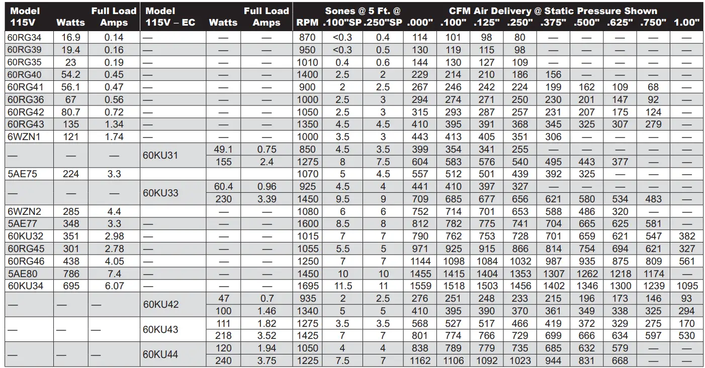
SPECIFICATIONS
| Max. Inlet Temp. | 104°F |
| Mounting Location | Ceiling, Horizontal or Vertical Discharge |
| Housing Material | Galvanized Steel |
| Agency Compliance | UL/cUL 507, AMCA Sound and Air, Energy Star® |
NOTE: Models 60RG34, 60RG35, 60RG36, 60RG39, 60RG40, 60RG41, 60RG42, 60RG43and 60KU42 are acceptable for use over a bathtub or shower when installed in a GFCI protected branch circuit.![]() Dayton Electric Mfg. Co. certifies that the ventilators shown herein are licensed to bear the AMCA seal. The ratings shown are based on tests and procedures performed in accordance with AMCA Publication 211 and AMCA Publication 311and comply with the requirements of the AMCA Certified Ratings Program. Energy Star®
Dayton Electric Mfg. Co. certifies that the ventilators shown herein are licensed to bear the AMCA seal. The ratings shown are based on tests and procedures performed in accordance with AMCA Publication 211 and AMCA Publication 311and comply with the requirements of the AMCA Certified Ratings Program. Energy Star®  Certified models include:
60RG34, 60RG39, 60RG35, 60RG41, 60RG40 and 60RG36
| Singlewide | 60RG34 13-1/2 x 10-7/8 | 60R035 60RG39 60RG40 | 60RG36 60RG41 60RG42 | 60KU42 14-1/4 x 12-1/8 | 5AE75 6WZN1 18-1/4 x | 60KU31 60KU33 18-1/4 x | 5AE77 6WZN2 |
| Recommended Ceiling Opening (inches) | 13-1/2 x 10-7/8 | 60RG43 14-1/4 x 12-1/8 | 14-5/8 | 14-5/8 | 18-1/4 x 14-5/8 | ||
| Recommended Duct Sizes (inches) | 6 Dia. | 8 x 6 | 8 x 8 | 8X8 | 8 x 8 | 8 x 8 | 10 x 8 |
| Recommended Speed Control Doublewide | 48C172 60KU32 | 48C172 60KU43 | 48C172 60RG45 | 35YV94 43Y140 60KU44 | 48C172 60RG46 5AE80 60KU34 | 35YV94 | 48C172
|
| Recommended Ceiling Opening (inches) | 23-7/8 x 11-7/8 | 23-7/8 x 11-7/8 | 24 x 14-5/8 | 24 x 14-5/8 | 24 x 14-5/8 | ||
| Recommended Duct Sizes (inches) | 19-1/2 x 8 | 19-1/2 x 8 | 18-314 x 8 | 17-7/16 x 8 | 18-3/4 x 8 | ||
| Recommended Speed Control | 48C172 | 35YV94 43Y140 | 48C172 | 35YV94 43Y140 | 48C173 |
|
TYPICAL INSTALLATION
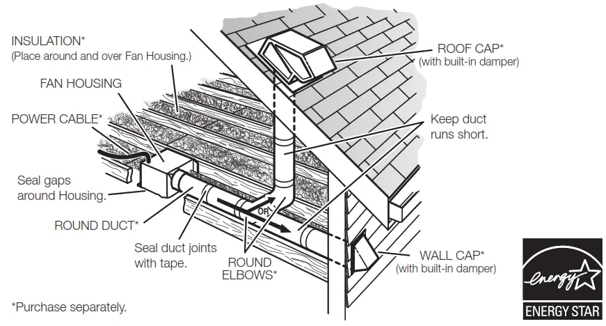
The ducting from this fan to the outside of the building has a strong effect on the air flow, noise and energy use of the fan. Use the shortest, straightest duct routing possible for best performance, and avoid installing the fan with smaller ducts than recommended. Insulation around the ducts can reduce energy loss and inhibit mold growth. Fans installed with existing ducts may not achieve their rated airflow.
Rigid metal duct is recommended for optimal fan performance.
Ensure duct joints and exterior penetrations are sealed with caulk or other similar material to create an air-tight path and to minimize building heat loss and gain and reduce the potential for condensation.
Place/wrap insulation around duct and/or fan to in order to minimize possible condensation buildup within the duct, as well as minimize building heat loss and gain.
| Energy Stare Certified Fan Model/Size | Recommended Duct Dimensions |
| 60RG34 | 6 inch round |
| 60RG35, 60RG39, 60RG40 | 8 x 6 inch rectangular |
| 60RG36, 60RG41 | 8 x 8 inch rectangular |
OTHER INSTALLATION CONSIDERATIONS
Ductwork and Noise
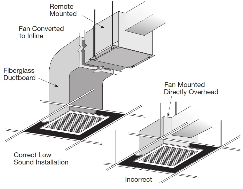
Fiberglass ductboard is a better choice than metal ductwork for reducing fan noise and is highly recommended for low sound applications. Where metal duct is used, sound transmission can be reduced with flexible duct connections between the fan and the duct.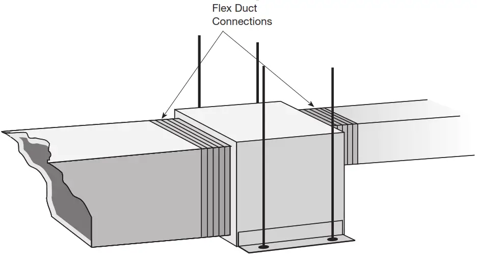 Sound and Location
The location of these fans must be taken into consideration before installation. In critical sound installations, insulated ductwork, flexible duct connections or placing the fan in a remote section of ductwork are solutions to meeting the required fan sound levels.
PREPARE THE FAN
Remove Wiring Knockout
Remove either top or side wiring knockout, depending on wiring direction, by bending it back and forth to break tabs.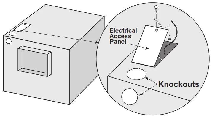 Ductwork
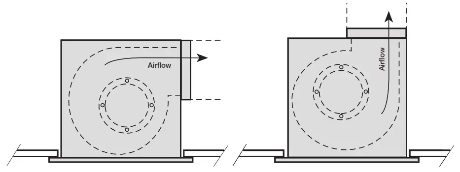
Check ductwork to see if the fan’s discharge requires rotation from horizontal to vertical discharge.
Fan Rotation
To rotate from horizontal to vertical discharge A Models Only
Models: 60RG34, 60RG35,
60RG36, 60RG39, 60RG40,
60RG41, 60RG42, 60RG43,
5AE75, 5AE77 , 6WZN1, 6WZN2,
60KU31, 60KU33, 60KU42
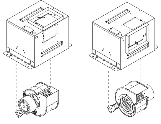
Remove the two screws holding the power assembly in and pull power assembly out. Rotate power assembly 180 degrees and put back into fan. Use the same screws to reattach power assembly to fan housing. Flip fan over and remove the four screws holding the discharge duct and damper assembly. Exchange the assembly with plate mounted on top of fan, as shown in these illustrations.
Models: 60RG45, 60RG46, 5AE80, 60KU32, 60KU34, 60KU43, 60KU44
Remove the eight screws holding the access panel or collar as shown in picture. Rotate the fan housing so the discharge is facing up. Replace access panel or collar and screws.
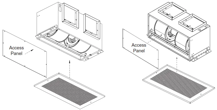
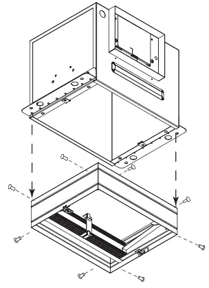
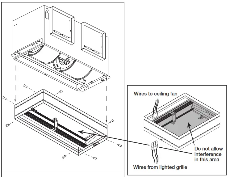
Ceiling Radiation Damper (CRD)
If fan is to be used in a fire resistive membrane ceiling, a ceiling radiation damper must be used.
If the ceiling radiation damper is already mounted to the fan from the factory, proceed to Install the Fan.
To mount the ceiling radiation damper to fan, make sure grille attachment tabs are facing down. Then place the inlet part of the fan into the ceiling radiation damper collar, and use self-tapping sheet metal screws (by others) to screw through the damper collar and into the fan housing. If the fan/light combination is being used, make sure ceiling radiation damper has an electrical plug in it. The electrical plug must be inserted into the fan. Make sure the electrical wire will not interfere with damper operation as shown in figure below.
Models: 60RG34, 60RG35, 60RG36, 60RG39, 60RG40, 60RG41, 60RG42, 60RG43, 5AE75, 5AE77 ,6WZN1, 6WZN2, 60KU31, 60KU33, 60KU42
Models: 60RG45, 60RG46, 5AE80, 60KU32, 60KU34, 60KU43, 60KU44
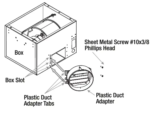
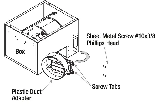
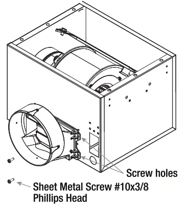
Discharge Installation 60RG34 Models
- Insert plastic duct tab into box slots.

- Rotate plastic duct adapter until the screw tabs meet the box.

- Install screws provided to secure discharge.

INSTALLATION INSTRUCTIONS
- For best performance, choose a location with the shortest possible duct run and minimum number of elbows. Do not mount near cooking equipment, as shown in Fig. 1.
- Attach adjustable mounting brackets to fan, but leave the screws loose until proper height is determined, shown in Fig. 2. Cut hole to dimensions shown in table below. For Frame Construction:
 Position unit between joists. Position brackets such that bottom edge of housing will be flush with finished ceiling, and tighten the adjustable mounting brackets, shown in Fig. 3.
 - Installation of ductwork is critical to the performance of the fan, shown in Fig.4. Straight ductwork (1) or ductwork that turns in the same direction as the wheel (2) is recommended. Ductwork turning opposite the wheel direction (3) will cause turbulence and back pressure resulting in poor performance.
- Slide ductwork over the fan’s discharge collar and securely attach it with sheet metal screws.
Make sure the screws do not interfere with damper operation. Check damper to make sure it opens freely.
Note: Model 60RG34 is standard with a round duct. Should any model require a round duct, Round Duct Connector (6WZP3 or 6WZP2) may be ordered from manufacturer for field installation.
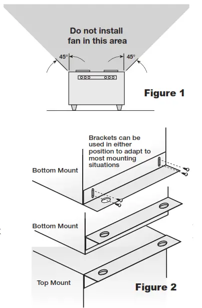 Position unit between joists. Position brackets such that bottom edge of housing will be flush with finished ceiling, and tighten the adjustable mounting brackets, shown in Fig. 3.
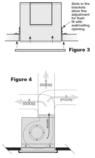
| Ceiling Openings | |
| Ceiling Exhaust Sizes | Fan/CRD |
| 60RG34, 60RG35, 60RG39′ 6ORG40 | 111/8x 137/18 |
| 60RG36, 60RG41, 60RG42, 60RG43, 60KU42 | 121/4 x 14% |
| 60KU32, 60KU43 | 241/8x 121/4 |
| 5AE75, 5AE77, 6WZN1, 6 ZN2, 60KU31, 60KU33 | 147/8 x 187/8 |
| 60RG45, 60RG46, 5AE80, 60KU34, 60KU44 | 14/8 x 241/4 |
WIRE THE FAN
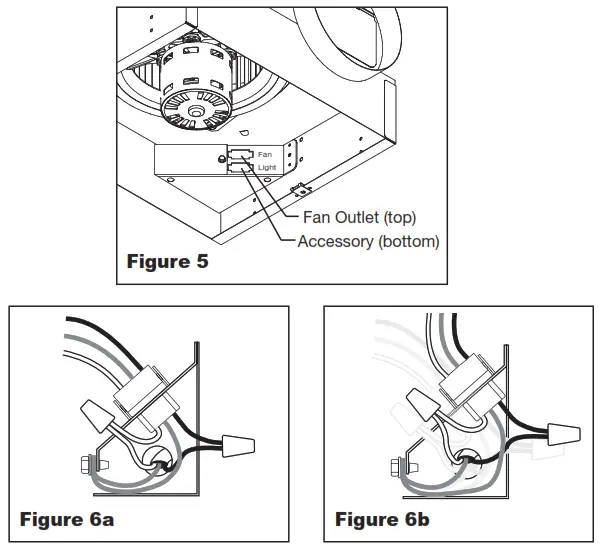
- Remove wiring cover. If fan/accessory combination is being used, make sure the fan plug is connected to the fan receptacle and the accessory plug is connected to the accessory receptacle, shown in Fig. 5. Using proper wire connectors, wire the fan as shown in Fig. 6a. For wiring of light proceed to Fig. 6b.
- Push all wiring into the unit’s cover and replace wiring cover.
| 115 & 277 Volt Black wire is “Hot” White wire is “Neutral” Green wire is “Ground” | 220 – 240 Volt Black wire is “Hot” White wire is “Hot” Green wire is “Neutral/Ground” |
ATTACH THE GRILLE
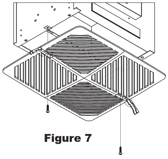
- Attach grille with two screws provided. Make ure not to over tighten; over tightening will damage grille.
- Slide attachment screw covers over the attachment screws, shown in Figure 7.
TROUBLESHOOTING GUIDE
| Symptom Ventilator inoperative | Possible Cause(s) 1.Blown fuse or breaker 2.Defective motor 3.Incorrectly wired | Corrective Action 1.Replace or repair 2.Replace or repair 3.Shut power OFF and check wiring for proper connections |
| Excessive noise or vibration | 1.Accumulation of material on wheel 2.Fan wheel out of balance | 1.Clean 2.Replace wheel |
| Insufficient airflow | 1.Blocked duct or clogged filters 2.Collapsed or perforated duct | 1.Clean or replace 2.Repair or replace duct section |
| Motor overloads or overheats | 1.Shorted motor winding 2.Incorrect voltage input 3.Buildup of dust, dirt or other contaminants on motor | 1.Replace motor 2.Correct to 115V 3.Clean motor |
MAINTENANCE
![]() WARNING
WARNING
Disconnect the power source before working on the unit.
Maintenance should be done yearly or as conditions warrant.
- The ventilator motor, wheel, housing and grille should be checked for dust and dirt accumulations. Dirt buildup can lead to loss of performance and motor overheating.
a. Remove grille. Using a vacuum cleaner with appropriate attachments, vacuum dust from grille. Wash grille with warm, soapy solution of water. Allow grille to dry thoroughly before re-installing.
b. To clean wheel and housing, unplug motor from the integral terminal box. Vacuum the wheel. If necessary, the wheel can be washed. Wipe the wheel dry with an absorbent cloth. Wipe out the interior of the housing. Plug blower motor into terminal box.
c. Lubricate only those motors which a have an oil hole provided. A few drops of all purpose oil (SAE 20) will be sufficient.
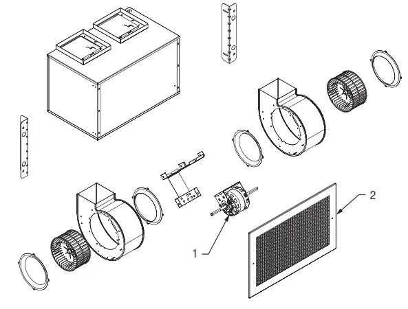
REPAIR PARTS ILLUSTRATION FOR SINGLEWIDE INSULATED VENTILATORS
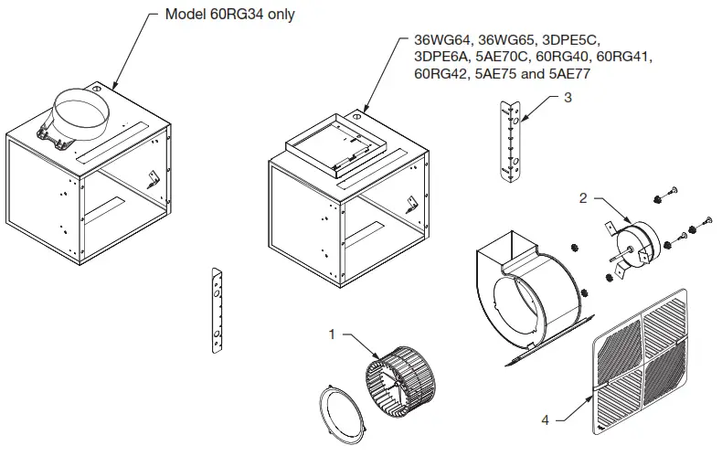
REPAIR PARTS ILLUSTRATION FOR DOUBLEWIDE INSULATED VENTILATORS
For Repair Parts, call 1-800-Grainger
24 hours a day – 365 days a year
Please provide following information:
- Model number
- Serial number (if any)
- Part description and number as shown in parts list
REPAIR PARTS LIST FOR SINGLEWIDE INSULATED VENTILATORS
| Ref. | Part Number for Models: | ||||||
| No. | Description | 60RG34 | 60RG35 | 60RG36 | 60RG39 | 60RG40 | Qty |
| 1 | Wheel | 21EC04 | 21EC04 | 21ECO5 | 21EC04 | 21EC04 | 1 |
| 2 | Motor | 21DY26 | 21DY27 | 21DY28 | 21EC38 | 34G193 | 1 |
| 3 | Mounting Bracket Kit | 21EA91 | 21EA91 | 21EA92 | 21EA91 | 21EA91 | 1 |
| 4 | Grille | 793K37 | 793K37 | 793K37 | 793K37 | 793K37 | 1 |
| Ref. | Part Number for Models: | ||||||
| No. | Description | 60RG41 | 60RG42 | 60RG43 | 5AE77 | 5AE75 | Qty |
| 1 | Wheel | 21ECO5 | 21ECO5 | 21ECO5 | 21EC06 | 21EC06 | 1 |
| 2 | Motor | 21EC10 | 21EC40 | 21EC11 | 21EC41 | 21DV64 | 1 |
| 3 | Mounting Bracket Kit | 21EA92 | 21EA92 | 21EA92 | 21EA93 | 21EA93 | 1 |
| 4 | Grille | 793K37 | 793K37 | 793K37 | 21EA87 | 21EA87 | 1 |
| Ref. | Part Number for Models: | ||||||
| No. | Description | 6WZN1 | 6WZN2 | 60KU31 | 60KU33 | 60KU42 | Qty |
| 1 | Wheel | 21DV70 | 21DV69 | 21EC06 | 21EC06 | 21ECO5 | 1 |
| 2 | Motor | 21 DV63 | 21 DV62 | 60YG51 | 60YG52 | 60YG53 | 1 |
| 3 | Mounting Bracket Kit | 21EA93 | 21EA93 | 21EA93 | 21EA93 | 21EA92 | 1 |
| 4 | Grille | 21EA87 | 21EA87 | 21 EA87 | 21EA87 | 793K37 | 1 |
| Ref. | Part Number for Models: | ||||||
| No | Description | 60KU32 | 60RG45 | 60RG46 | 5AE80 | 60KU34 | Qty |
| 1 | Motor | 21EC12 | 21EC42 | 21EC43 | 21EC44 | 21EC45 | 1 |
| 2 | Grille | 21EA89 | 21EA88 | 21EA88 | 21EA88 | 21EA88 | 1 |
| Ref. | Part Number for Models: | |||
| No. | Description | 60KU43 | 60KU44 | Qty |
| 1 | Motor | 60YG54 | 60YG55 | 1 |
| 2 | Grille | 21EA89 | 21EA88 | 1 |
† Includes (2) scrolls and motor bracket fully assembled, requires purchase of (2) wheels if needed.
DAYTON ONE-YEAR LIMITED WARRANTY
DAYTON ONE-YEAR LIMITED WARRANTY. All Dayton ® product models covered in this manual are warranted by Dayton Electric Mfg. Co. (“Dayton”) to the original user against defects in workmanship or materials under normal use for one year after date of purchase. If the Dayton product is part of a set, only the portion that is defective is subject to this warranty. Any product or part which is determined to be defective in material or workmanship and returned to an authorized service location, as Dayton or Dayton’s designee designates, shipping costs prepaid, will be, as the exclusive remedy, repaired or replaced with a new or reconditioned product or part of equal utility or a full refund given, at Dayton’s or Dayton’s designee’s option, at no charge. For limited warranty claim procedures, see “Warranty Service” below. This warranty
is void if there is evidence of misuse, mis-repair, mis-installation, abuse or alteration. This warranty does not cover normal wear and tear of Dayton products or portions of them, or products or portions of them which are consumable in normal use. This limited warranty gives purchasers specific legal rights, and you may also have other rights which vary from jurisdiction to jurisdiction.
WARRANTY DISCLAIMERS AND LIMITATIONS OF LIABILITY RELATING TO ALL CUSTOMERS FOR ALL PRODUCTS
LIMITATION OF LIABILITY. TO THE EXTENT ALLOWABLE UNDER APPLICABLE LAW, DAYTON’S LIABILITY FOR CONSEQUENTIAL AND INCIDENTAL DAMAGES IS EXPRESSLY DISCLAIMED. DAYTON’S LIABILITY IN ALL EVENTS IS LIMITED TO AND SHALL NOT EXCEED THE PURCHASE PRICE PAID.
WARRANTY DISCLAIMER. A DILIGENT EFFORT HAS BEEN MADE TO PROVIDE PRODUCT INFORMATION AND ILLUSTRATE THE PRODUCTS IN THIS LITERATURE ACCURATELY; HOWEVER, SUCH INFORMATION AND ILLUSTRATIONS ARE FOR THE SOLE PURPOSE OF IDENTIFICATION, AND DO NOT EXPRESS OR IMPLY A WARRANTY THAT THE PRODUCTS ARE MERCHANTABLE, OR FIT FOR A PARTICULAR PURPOSE, OR THAT THE PRODUCTS WILL NECESSARILY CONFORM TO THE ILLUSTRATIONS OR DESCRIPTIONS. EXCEPT AS PROVIDED BELOW, NO WARRANTY OR AFFIRMATION OF FACT, EXPRESSED OR IMPLIED, OTHER THAN AS STATED IN THE “LIMITED WARRANTY” ABOVE IS MADE OR AUTHORIZED BY DAYTON.
PRODUCT SUITABILITY. MANY JURISDICTIONS HAVE CODES AND REGULATIONS GOVERNING SALES, CONSTRUCTION, INSTALLATION, AND/OR USE OF PRODUCTS FOR CERTAIN PURPOSES, WHICH MAY VARY FROM THOSE IN NEIGHBORING AREAS. WHILE ATTEMPTS ARE MADE TO ASSURE THAT DAYTON PRODUCTS COMPLY WITH SUCH CODES, DAYTON CANNOT GUARANTEE COMPLIANCE, AND CANNOT BE RESPONSIBLE FOR HOW THE PRODUCT IS INSTALLED OR USED. BEFORE PURCHASE AND USE OF A PRODUCT, REVIEW THE SAFETY/SPECIFICATIONS, AND ALL APPLICABLE NATIONAL AND LOCAL CODES AND REGULATIONS, AND BE SURE THAT THE PRODUCT, INSTALLATION, AND USE WILL COMPLY WITH THEM.
CONSUMERS ONLY. CERTAIN ASPECTS OF DISCLAIMERS ARE NOT APPLICABLE TO CONSUMER PRODUCTS SOLD TO CONSUMERS; (A) SOME JURISDICTIONS DO NOT ALLOW THE EXCLUSION OR LIMITATION OF INCIDENTAL OR CONSEQUENTIAL DAMAGES, SO THE ABOVE LIMITATION OR EXCLUSION MAY NOT APPLY TO YOU; (B) ALSO, SOME JURISDICTIONS DO NOT ALLOW A LIMITATION ON HOW LONG AN IMPLIED WARRANTY LASTS, SO THE ABOVE LIMITATION MAY NOT APPLY TO YOU; AND (C) BY LAW, DURING THE PERIOD OF THIS LIMITED WARRANTY, ANY IMPLIED WARRANTIES OF MERCHANTABILITY OR FITNESS FOR A PARTICULAR PURPOSE APPLICABLE TO CONSUMER PRODUCTS PURCHASED BY CONSUMERS, MAY NOT BE EXCLUDED OR OTHERWISE DISCLAIMED.
THIS LIMITED WARRANTY ONLY APPLIES TO UNITED STATES PURCHASERS FOR DELIVERY IN THE UNITED STATES.
WARRANTY SERVICE
To obtain warranty service if you purchased the covered product directly from W.W. Grainger, Inc. (“Grainger”),
(i) write or call or visit the local Grainger branch from which the product was purchased or another Grainger branch near you (see www.grainger.com for a listing of Grainger branches); or
(ii) contact Grainger by going to www.grainger.com and clicking on the “Contact Us” link at the top of the page, then clicking on the “Email us” link; or
(iii) call Customer Care (toll free) at 1-888-361-8649. To obtain warranty service if you purchased the covered product from another distributor or retailer,
(i) go to www.grainger.com for Warranty Service;
(ii) write or call or visit a Grainger branch near you; or
(iii) call Customer Care (toll free) at 1-888-361-8649. In any case, you will need to provide, to the extent available, the purchase date, the original invoice number, the stock number, a description of the defect, and anything else specified in this Dayton One-Year Limited Warranty. You may be required to send the product in for inspection at your cost. You can follow up on the progress of inspections and corrections in the same ways. Title and risk of loss pass to buyer on delivery to common carrier, so if product was damaged in transit to you, file claim with carrier, not retailer, Grainger or Dayton. For warranty information for purchasers and/or delivery outside the United States, please use the following applicable contact information:
![]() MARCH 2022
MARCH 2022
Dayton Electric Mfg. Co.,
100 Grainger Parkway, Lake Forest, IL 60045 U.S.A.
or call +1-888-361-8649
DM_US 44930530-6.019350.0029


