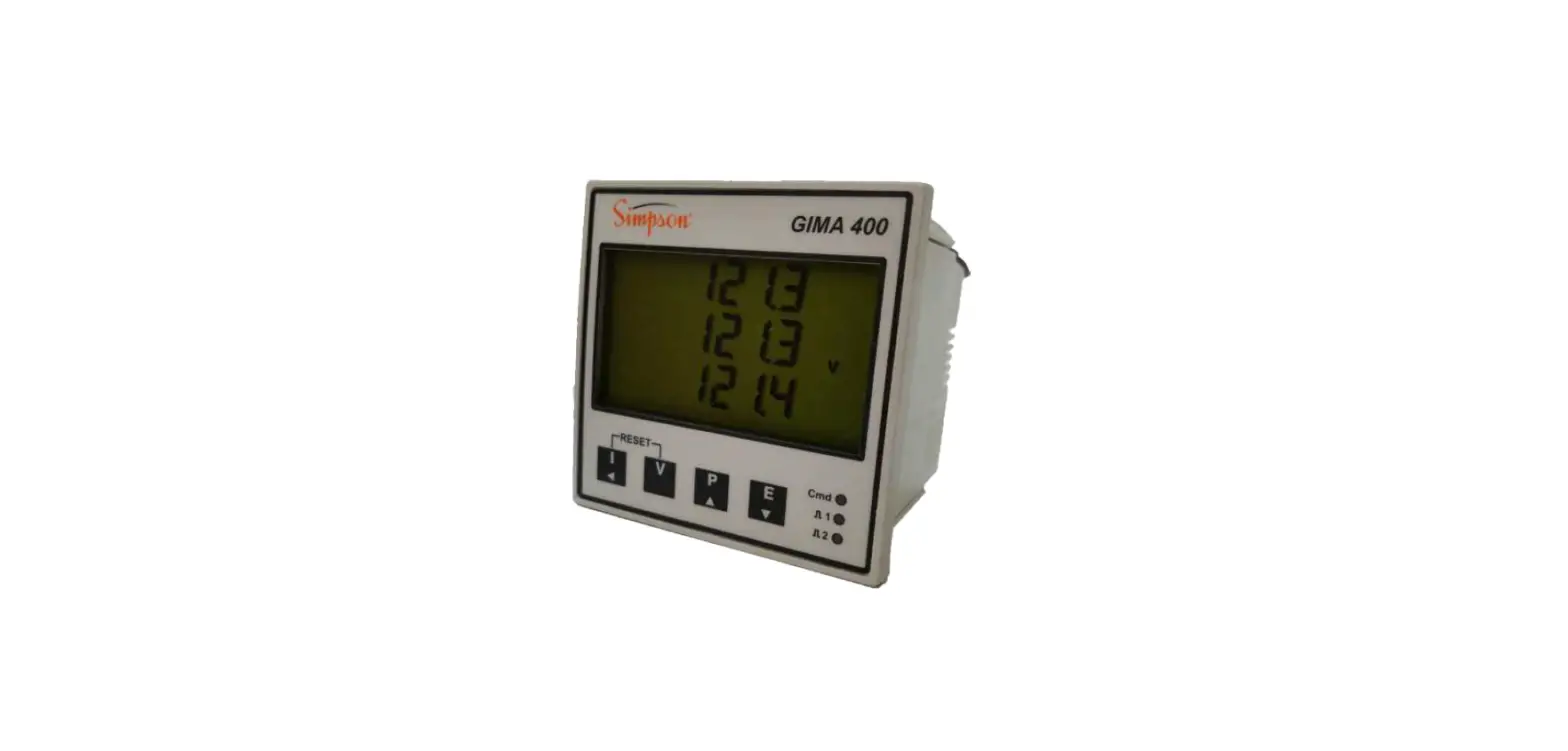
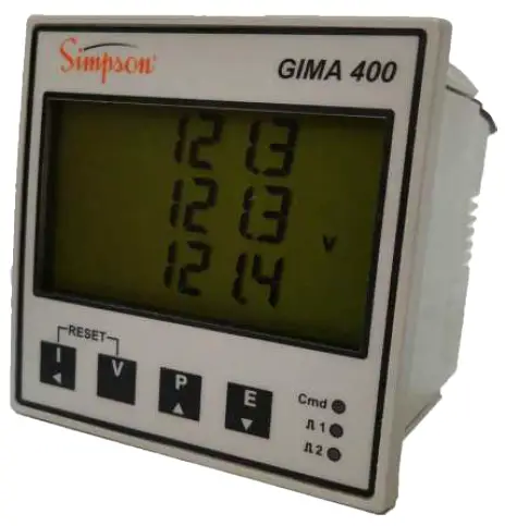
Simpson GIMA400 Digital Power Meters
Safety
The GIMA400 is intended for connection to dangerous voltages giving a risk of electric shock. Refer to the safety/installation instructions in the GIMA400 Installation Guide before connecting the communications.
WARNING
The meter contains no user serviceable parts. Installation and commissioning should only be carried out by qualified personnel
For further Information contact the manufacturer:
Address: Simpson Electric Company 520 Simpson Avenue Lac Du Flambeau, WI. (USA)
Web: www.simpsonelectric.com
Email: [email protected]
Programming
Meters fitted with the Modbus option have two additional stages in the front panel programming menu.
To enter programming mode:
- Hold and together for 5 Seconds.
- Press repeatedly until the required setup page is displayed.
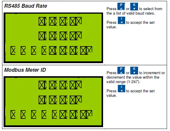
For full information on entering and using programming mode refer to the latest “GIMA400
Connection
Cable Selection
A dedicated, screened twisted pair cable is required to provide basic RS485 connection. A second twisted pair may be used for 0V connection if required. The cable should be chosen to suit the data rate and maximum length to be installed. The EIA RS-485-A standard provides curves that relate cable length to data rate for 24 AWG screened, twisted pair, telephone cable with a shunt capacitance of 50pf/m. For baud rates up to 19,200 the standard suggests a maximum length of 1200m for this type of cable. If other types of cable are to be used it is recommended that the cable supplier is consulted as to the suitability for use with RS485 to 19,200 baud.
Signal 0V and Cable Shield
- A signal 0V termination is provided on each meter. Although RS485 does not strictly require a signal 0V, it is recommended this is connected as shown in the diagram below. This creates a known reference for the isolated RS485 system thereby reducing potential common-mode errors in the meter’s RS485 driver circuit.
- A cable shield is used to attenuate noise picked up from external sources. This should be continuous, and cover as much of the signal pairs as possible. It is recommended that the shield should be connected to ground at the host (PC) only. The cable shield should not be used as the 0V connection.
Terminating Resistors
In order to minimise signal errors due to noise over long cable lengths, terminating resistors may be fitted. These match the RS485 device impedance to that of the cable. Two 120 resistors, one at the host port terminals and the other at the most remote meter terminals are recommended for this purpose.
Connection To Meters
The bus wires should be taken to meters at each location for termination, using the meter terminals as a loop in-out connection. 3-Pairs of terminals, internally shorted, are provided for convenience. The use of spurs should be avoided wherever possible.
Basic Connection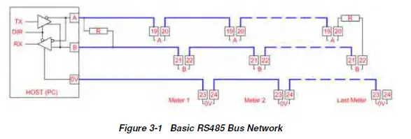
Protocol
Modbus Commands
The GIMA400 meter supports the following standard Modbus commands
| Command | Function | Broadcast |
| 03 | Read Multiple Holding Registers | No |
| 04 | Read Multiple Input Registers | No |
| 06 | Preset a Single Register | Yes |
| 08 (SF=00) | Sub Function 00 only (Loop Back) | No |
| 16 | Preset Multiple Registers | Yes |
Exception Responses
If the meter receives a Modbus command, with no errors and a valid address, it will attempt to handle the query and provide an appropriate response. If the meter cannot handle the query a standard Modbus exception response is sent (except broadcast queries). An exception response is characterised by its function byte which has 80H added to that sent in the query. The following exceptions codes are supported:
| Code | Function |
| 1 | Preset data is out of range for parameter |
| 2 | Function cannot access requested register address |
Modbus Data Tables
Using The Tables
For convenience, meter data is organised in tables of like information with the same format. An entire table may be read with a single Modbus command 3 (Holding Registers). For compatibility with the Modbus standard each register contains a single data Word (16 bits). Data in the meter is stored as:
Unsigned Integer (U-INT)
16-bit data in the range 0 to 65,535. This is used for parameters such as CT prim as this can never be negative.
Signed Integer (S-INT)
16-bit data in the range –32,768 to +32,767. This is used for parameters such as instantaneous kW, which may have a negative value indicating export power.
Long Integer (LONG)
32-bit data in the range 0 to 4,294,967,295. This is used for parameters such as kWh, which may have large values. Each LONG requires two consecutive Modbus data words. Standard software often handles long integer reads, however, a LONG may be calculated from the individual data words as:
Energy Registers
| Data Address | Modbus Register | Data | Access |
| 512 | 40513 | eScale High Word | Read Only |
| 513 | 40514 | eScale Low Word | |
| 514 | 40515 | kWh High Word | Read/Write |
| 515 | 40516 | kWh Low Word | |
| 516 | 40517 | kVAh High Word | Read/Write |
| 517 | 40518 | kVAh Low Word | |
| 518 | 40519 | kvarh Inductive High Word | Read/Write |
| 519 | 40520 | kvarh Inductive Low Word | |
| 520 | 40521 | kvarh Capacitive High Word | Read/Write |
| 521 | 40522 | kvarh Capacitive Low Word | |
| 522 | 40523 | Import kvarh High Word | Read/Write |
| 523 | 40524 | Import kvarh Low Word | |
| 524 | 40525 | Export kWh High Word | Read/Write |
| 525 | 40526 | Export kWh Low Word | |
| 526 | 40527 | Export kvarh High Word | Read/Write |
| 527 | 40528 | Export kvarh Low Word | |
| 528 | 40529 | Hours Run High Word | Read/Write |
| 529 | 40530 | Hours Run Low Word |
Energy registers are stored as long integer representations of the number displayed on the meter
without decimal point or scaling. For example if the meter displays 123456.78kWh, the Holding Registers 40515-40516 will contain the long integer 12345678. This number may be scaled in Wh or kWh, using eScale as:
- Wh = Holding Reg[40516] x 10(eScale-3)
- kWh = Holding Reg[40516] x 10(eScale-6)
The eScale constant is set, along with the kWh register resolution and scaling, by the CT primary and nominal voltage programmed settings. The display scaling and eScale therefore remain constant once a meter is installed and commissioned. A read of eScale High Word always returns zero.
Example:
If the meter displays 1234567.8 kWh then eScale would be 5 and the Holding Registers 40515- 40516 would contain 12345678.
The host would calculate the scaled energy reading as:
12345678 x 10(5-3) = 12345678 x 100 = 1,234,567,800 Wh or 12345678 x 10(5-6) = 12345678 x 0.1 = 1,234,567.8 kWh
The host programmer could take two approaches to interpreting the data from the meter:
- Enter a fixed scaling factor (x100 for Wh or x0.1 for kWh in above example). This would be set for each meter in the system based on its display after commissioning.
- Use the transmitted eScale constant, as shown above, to automatically position the decimal point in the interpreted result.
Instantaneous Meter Values
| Data Address | Modbus Register | Data | Scaling |
| 2816 | 42817 | System kW | Kp |
| 2817 | 42818 | System kVA | Kp |
| 2818 | 42819 | System kvar | Kp |
| 2819 | 42820 | System PF | 1000 = 1.000 |
| 2820 | 42821 | Frequency | 500 = 50.0 |
| 2821 | 42822 | Phase 1 Volts | Kvp |
| 2822 | 42823 | Phase 1 Amps | Ki |
| 2823 | 42824 | Phase 1 kW | Kp |
| 2824 | 42825 | Phase 2 Volts | Kvp |
| 2825 | 42826 | Phase 2 Amps | Ki |
| 2826 | 42827 | Phase 2 kW | Kp |
| 2827 | 42828 | Phase 3 Volts | Kvp |
| 2828 | 42829 | Phase 3 Amps | Ki |
| 2829 | 42830 | Phase 3 kW | Kp |
| 2830 | 42831 | Phase 1 PF | 1000 = 1.000 |
| 2831 | 42832 | Phase 2 PF | 1000 = 1.000 |
| 2832 | 42833 | Phase 3 PF | 1000 = 1.000 |
| 2833 | 42834 | Ph1-Ph2 Volts | Kvl |
| 2834 | 42835 | Ph2-Ph3 Volts | Kvl |
| 2835 | 42836 | Ph3-Ph1 Volts | Kvl |
| 2836 | 42837 | Neutral Current | Ki |
| 2837 | 42838 | Amps Scale Ki | – |
| 2838 | 42839 | Phase Volts Scale Kvp | – |
| 2839 | 42840 | Line Volts Scale Kvl | – |
| 2840 | 42841 | Power Scale Kp | – |
Note: All registers in this table have read only access.
Instantaneous readings are provided as signed integer values with no decimal point or legend (e.g. kW or MW). Scaling factors are provided to enable conversion of the raw data to real numbers inbasic unit form (amps, volts, watts, VA, or var). These scaling factors are constant values calculated as a function of CT and PT Primary programming. To convert raw data to real numbers
- R = I x 10(K-3)
Where:
- I = Integer number
- K = Relevant Scaling Factor
- R = Real number result
Example:
- If the meter is programmed with CT Primary=50Amps and PT Primary=415V:
- LCD values would be scaled as: 50.00A, 240.0V, 415.7VLL and 36.00kW.
- Scaling factors would be: I Scale=1, Kvp=2, Kvl=2, Kp=4.
- Integer Values would be transmitted as: 5000, 2400, 4157 and 3600
- Amps would be calculated as 5000 x 10(1-3) = 5000/100 = 50.00A
- Phase Volts would be calculated as 2400 x 10(2-3) = 2400/10 = 240.0V
- Line Volts would be calculated as 4157 x 10(2-3) = 4157/10 = 415.7V
- 3-Ph Power would be calculated as 3600 x 10(4-3) = 3600×10 = 36000W
Additional Instantaneous Values
| Data Address | Modbus Register | Data | Scaling |
| 3072 | 43073 | Phase 1 kVA | Kp |
| 3073 | 43074 | Phase 2 kVA | Kp |
| 3074 | 43075 | Phase 3 kVA | Kp |
| 3075 | 43076 | Phase 1 kvar | Kp |
| 3076 | 43077 | Phase 2 kvar | Kp |
| 3077 | 43078 | Phase 3 kvar | Kp |
Note: All values in this table are Signed Integers with read only access.
Peak Hold Values
| Data Address | Modbus Register | Data | Scaling |
| 3328 | 43329 | Peak Hold Ph1 Amps | Ki |
| 3329 | 43330 | Peak Hold Ph2 Amps | Ki |
| 3330 | 43331 | Peak Hold Ph3 Amps | Ki |
| 3331 | 43332 | Peak Hold Ph1 Volts | Kvp |
| 3332 | 43333 | Peak Hold Ph2 Volts | Kvp |
| 3333 | 43334 | Peak Hold Ph3 Volts | Kvp |
| 3334 | 43335 | Peak Hold kW Demand | Kp + 1 |
| 3335 | 43336 | KW Demand Period | 1-60 Minutes |
| 3336 | 43337 | KW Demand | Kp + 1 |
| 3337 | 43338 | KVA Demand | Kp + 1 |
| 3338 | 43339 | Peak Hold kVA Demand | Kp + 1 |
| 3339 | 43340 | Kvar Demand | Kp + 1 |
| 3340 | 43341 | Peak Hold kvar Demand | Kp + 1 |
Note: All values in this table are Signed Integers(amps & Volts parameters) and unsigned integers ( power demands) with read/write access except 43337, 43338 and 43340 which have read only access.
Meter Setup
| Data Address | Modbus Register | Data | Scaling |
| 3584 | 43585 | CT Primary | 10 – 25,000 Amps |
| 3585 | 43586 | Nominal Volts | 10 – 55,000 Volts |
| 3586 | 43587 | Pulse 1 Rate | 1-1000 Counts/Pulse |
| 3587 | 43588 | Pulse 2 Rate (= Pulse 1 Rate) | 1-1000 Counts/Pulse |
| 3588 | 43589 | Baud | 96 = 9600baud etc |
| 3589 | 43590 | Modbus ID | 0 – 247 |
| 3590 | 43591 | Meter Model | Cube400 = 400 |
| 3591 | 43592 | Meter Type | Basic Cube400 = 1 |
| 3592 | 43593 | Firmware Version | Eg. 0x14 = 1.04 |
| 3593 | 43594 | Current Demand Period | 1 = 10Sec, 2=20Sec etc |
| 3594 | 43595 | Pulse ON Time | 1 = 100ms, 2=200ms etc |
| 3595 | 43596 | Security Code | 0 – 9999 |
| 3596 | 43597 | Hours Run Limit | 0–9999kW (scaled as LCD) |
| 3597 | 43598 | PT Scaling Factor | 1 – 10 |
Note: All values in this table are unsigned Integers with read/write access except 43591-43593 which are read only.
The overall PT Primary is calculated as: Nominal Volts X PT scaling factor
Peak Hold Current/Voltage Demand
| Data Address | Modbus Register | Data | Scaling |
| 3840 | 43841 | Peak Ph1 Amps Demand | Ki |
| 3841 | 43842 | Peak Ph2 Amps Demand | Ki |
| 3842 | 43843 | Peak Ph3 Amps Demand | Ki |
| 3843 | 43844 | Peak Ph1 Volts Demand | Kvp |
| 3844 | 43845 | Peak Ph2 Volts Demand | Kvp |
| 3845 | 43846 | Peak Ph3 Volts Demand | Kvp |
Note: All values in this table are Unsigned Integers with read/write access.
Current/Voltage Demand
| Data Address | Modbus Register | Data | Scaling |
| 4096 | 44097 | Ph1 Amps Demand | Ki |
| 4097 | 44098 | Ph2 Amps Demand | Ki |
| 4098 | 44099 | Ph3 Amps Demand | Ki |
| 4099 | 44100 | Ph1 Volts Demand | Kvp |
| 4100 | 44101 | Ph2 Volts Demand | Kvp |
| 4101 | 44102 | Ph3 Volts Demand | Kvp |
Note: All values in this table are Unsigned Integers with read only access
Total Harmonic Distortion Values
| Data Address | Modbus Register | Data | Scaling |
| 4352 | 44353 | V1 % THD | 1000 = 100% |
| 4353 | 44354 | V2 % THD | 1000 = 100% |
| 4354 | 44355 | V3 % THD | 1000 = 100% |
| 4355 | 44356 | I1 % THD | 1000 = 100% |
| 4356 | 44357 | I2 % THD | 1000 = 100% |
| 4357 | 44358 | I3 % THD | 1000 = 100% |
Note: All values in this table are Unsigned Integers with read only access.
Power Demand Values
| Data Address | Modbus Register | Data | Scaling |
| 4608 | 44609 | kW Demand | Kp + 1 |
| 4609 | 44610 | kVA Demand | Kp + 1 |
| 4610 | 44611 | Kvar Demand | Kp + 1 |
| 4611 | 44612 | Peak Hold kW Demand | Kp + 1 |
| 4612 | 44613 | Peak Hold kVA Demand | Kp + 1 |
| 4613 | 44614 | Peak Hold kvar Demand | Kp + 1 |
Note: All values in this table are signed Integers. Demand values have read only access while peak hold values have read/write access
Amalgamated Data Table
| Data Address | Modbus Register | Data | Scaling |
| 7680 | 47681 | KWh High Word | Ke |
| 7681 | 47682 | KWh Low Word | |
| 7682 | 47683 | KVAh High Word | Ke |
| 7683 | 47684 | KVAh Low Word | |
| 7684 | 47685 | Kvarh High Word | Ke |
| 7685 | 47686 | Kvarh Low Word | |
| 7686 | 47687 | Export kWh High Word | Ke |
| 7687 | 47688 | Export kWh Low Word | |
| 7688 | 47689 | Phase 1 Amps | Ki |
| 7689 | 47690 | Phase 2 Amps | |
| 7690 | 47691 | Phase 3 Amps | |
| 7691 | 47692 | Phase 1 Volts | Kvp |
| 7692 | 47693 | Phase 2 Volts | |
| 7693 | 47694 | Phase 3 Volts | |
| 7694 | 47695 | Ph1-Ph2 Volts | Kvl |
| 7695 | 47696 | Ph2-Ph3 Volts | |
| 7696 | 47697 | Ph3-Ph1 Volts | |
| 7697 | 47698 | Frequency | 500 = 50.0 |
| 7698 | 47699 | Phase 1 PF | 1000 = 1.000 |
| 7699 | 47700 | Phase 2 PF | |
| 7700 | 47701 | Phase 3 PF | |
| 7701 | 47702 | System PF | |
| 7702 | 47703 | Phase 1 kW | Kp |
| 7703 | 47704 | Phase 2 kW | |
| 7704 | 47705 | Phase 3 kW | |
| 7705 | 47706 | System kW | |
| 7706 | 47707 | Phase 1 kVA | Kp |
| 7707 | 47708 | Phase 2 kVA | |
| 7708 | 47709 | Phase 3 kVA | |
| 7709 | 47710 | System kVA | |
| 7710 | 47711 | Phase 1 kvar | Kp |
| 7711 | 47712 | Phase 2 kvar | |
| 7712 | 47713 | Phase 3 kvar | |
| 7713 | 47714 | System kvar | |
| 7714 | 47715 | Ph1 Amps Demand | Ki |
| 7715 | 47716 | Ph2 Amps Demand | |
| 7716 | 47717 | Ph3 Amps Demand | |
| 7717 | 47718 | Ph1 Volts Demand | Kvp |
| 7718 | 47719 | Ph2 Volts Demand | |
| 7719 | 47720 | Ph3 Volts Demand | |
| 7720 | 47721 | Peak Ph1 Amps | Ki |
| 7721 | 47722 | Peak Ph2 Amps | |
| 7722 | 47723 | Peak Ph3 Amps | |
| 7723 | 47724 | Peak Ph1 Volts | Kvp |
| 7724 | 47725 | Peak Ph2 Volts | |
| 7725 | 47726 | Peak Ph3 Volts | |
| 7726 | 47727 | kW Demand | Kp + 1 |
| 7727 | 47728 | kVA Demand | |
| 7728 | 47729 | kvar Demand | |
| 7729 | 47730 | Peak Hold kW Demand | Kp + 1 |
| 7730 | 47731 | Peak Hold kVA Demand | |
| 7731 | 47732 | Peak Hold kvar Demand | |
| 7732 | 47733 | Neutral Current | Ki |
| 7733 | 47734 | Amps Scale Ki | – |
| 7734 | 47735 | Phase Volts Scale Kvp | – |
| 7735 | 47736 | Line Volts Scale Kvl | – |
| 7736 | 47737 | Power Scale Kp | – |
| 7737 | 47738 | Energy Scale Ke | – |
Note: All values in this table have read only access.
The amalgamated data table provides a copy of key variables in a single table, which may be read with a single Modbus command. The format and scaling of each parameter is identical to that found in the main tables
V1 Harmonics
| Data Address | Modbus Register | Data | Scaling |
| 7936 | 47937 | V1: 2nd Harmonic | 1000 = 100% |
| 7937 | 47938 | V1: 3rd Harmonic | 1000 = 100% |
| 7938 | 47939 | V1: 4th Harmonic | 1000 = 100% |
| 7939 | 47940 | V1: 5th Harmonic | 1000 = 100% |
| 7940 | 47941 | V1: 6th Harmonic | 1000 = 100% |
| 7941 | 47942 | V1: 7th Harmonic | 1000 = 100% |
| 7942 | 47943 | V1: 8th Harmonic | 1000 = 100% |
| 7943 | 47944 | V1: 9th Harmonic | 1000 = 100% |
| 7944 | 47945 | V1: 10th Harmonic | 1000 = 100% |
| 7945 | 47946 | V1: 11th Harmonic | 1000 = 100% |
| 7946 | 47947 | V1: 12th Harmonic | 1000 = 100% |
| 7947 | 47948 | V1: 13th Harmonic | 1000 = 100% |
| 7948 | 47949 | V1: 14th Harmonic | 1000 = 100% |
| 7949 | 47950 | V1: 15th Harmonic | 1000 = 100% |
V2 Harmonics
| Data Address | Modbus Register | Data | Scaling |
| 8192 | 48193 | V2: 2nd Harmonic | 1000 = 100% |
| 8193 | 48194 | V2: 3rd Harmonic | 1000 = 100% |
| 8194 | 48195 | V2: 4th Harmonic | 1000 = 100% |
| 8195 | 48196 | V2: 5th Harmonic | 1000 = 100% |
| 8196 | 48197 | V2: 6th Harmonic | 1000 = 100% |
| 8197 | 48198 | V2: 7th Harmonic | 1000 = 100% |
| 8198 | 48199 | V2: 8th Harmonic | 1000 = 100% |
| 8199 | 48200 | V2: 9th Harmonic | 1000 = 100% |
| 8200 | 48201 | V2: 10th Harmonic | 1000 = 100% |
| 8201 | 48202 | V2: 11th Harmonic | 1000 = 100% |
| 8202 | 48203 | V2: 12th Harmonic | 1000 = 100% |
| 8203 | 48204 | V2: 13th Harmonic | 1000 = 100% |
| 8204 | 48205 | V2: 14th Harmonic | 1000 = 100% |
| 8205 | 48206 | V2: 15th Harmonic | 1000 = 100% |
V3 Harmonics
| Data Address | Modbus Register | Data | Scaling |
| 8448 | 48449 | V3: 2nd Harmonic | 1000 = 100% |
| 8449 | 48450 | V3: 3rd Harmonic | 1000 = 100% |
| 8450 | 48451 | V3: 4th Harmonic | 1000 = 100% |
| 8451 | 48452 | V3: 5th Harmonic | 1000 = 100% |
| 8452 | 48453 | V3: 6th Harmonic | 1000 = 100% |
| 8453 | 48454 | V3: 7th Harmonic | 1000 = 100% |
| 8454 | 48455 | V3: 8th Harmonic | 1000 = 100% |
| 8455 | 48456 | V3: 9th Harmonic | 1000 = 100% |
| 8456 | 48457 | V3 10th Harmonic | 1000 = 100% |
| 8457 | 48458 | V3: 11th Harmonic | 1000 = 100% |
| 8458 | 48459 | V3: 12th Harmonic | 1000 = 100% |
| 8459 | 48460 | V3: 13th Harmonic | 1000 = 100% |
| 8460 | 48461 | V3: 14th Harmonic | 1000 = 100% |
| 8461 | 48462 | V3: 15th Harmonic | 1000 = 100% |
I1 Harmonics
| Data Address | Modbus Register | Data | Scaling |
| 8704 | 48705 | I1: 2nd Harmonic | 1000 = 100% |
| 8705 | 48706 | I1: 3rd Harmonic | 1000 = 100% |
| 8706 | 48707 | I1: 4th Harmonic | 1000 = 100% |
| 8707 | 48708 | I1: 5th Harmonic | 1000 = 100% |
| 8708 | 48709 | I1: 6th Harmonic | 1000 = 100% |
| 8709 | 48710 | I1: 7th Harmonic | 1000 = 100% |
| 8710 | 48711 | I1: 8th Harmonic | 1000 = 100% |
| 8711 | 48712 | I1: 9th Harmonic | 1000 = 100% |
| 8712 | 48713 | I1: 10th Harmonic | 1000 = 100% |
| 8713 | 48714 | I1: 11th Harmonic | 1000 = 100% |
| 8714 | 48715 | I1: 12th Harmonic | 1000 = 100% |
| 8715 | 48716 | I1: 13th Harmonic | 1000 = 100% |
| 8716 | 48717 | I1: 14th Harmonic | 1000 = 100% |
| 8717 | 48718 | I1: 15th Harmonic | 1000 = 100% |
I2 Harmonics
| Data Address | Modbus Register | Data | Scaling |
| 8960 | 48961 | I2: 2nd Harmonic | 1000 = 100% |
| 8961 | 48962 | I2: 3rd Harmonic | 1000 = 100% |
| 8962 | 48963 | I2: 4th Harmonic | 1000 = 100% |
| 8963 | 48964 | I2: 5th Harmonic | 1000 = 100% |
| 8964 | 48965 | I2: 6th Harmonic | 1000 = 100% |
| 8965 | 48966 | I2: 7th Harmonic | 1000 = 100% |
| 8966 | 48967 | I2: 8th Harmonic | 1000 = 100% |
| 8967 | 48968 | I2: 9th Harmonic | 1000 = 100% |
| 8968 | 48969 | I2: 10th Harmonic | 1000 = 100% |
| 8969 | 48970 | I2: 11th Harmonic | 1000 = 100% |
| 8970 | 48971 | I2: 12th Harmonic | 1000 = 100% |
| 8971 | 48972 | I2: 13th Harmonic | 1000 = 100% |
| 8972 | 48973 | I2: 14th Harmonic | 1000 = 100% |
| 8973 | 48974 | I2: 15th Harmonic | 1000 = 100% |
I3 Harmonics
| Data Address | Modbus Register | Data | Scaling |
| 9216 | 49217 | I3: 2nd Harmonic | 1000 = 100% |
| 9217 | 49218 | I3: 3rd Harmonic | 1000 = 100% |
| 9218 | 49219 | I3: 4th Harmonic | 1000 = 100% |
| 9219 | 49220 | I3: 5th Harmonic | 1000 = 100% |
| 9220 | 49221 | I3: 6th Harmonic | 1000 = 100% |
| 9221 | 49222 | I3: 7th Harmonic | 1000 = 100% |
| 9222 | 49223 | I3: 8th Harmonic | 1000 = 100% |
| 9223 | 49224 | I3: 9th Harmonic | 1000 = 100% |
| 9224 | 49225 | I3: 10th Harmonic | 1000 = 100% |
| 9225 | 49226 | I3: 11th Harmonic | 1000 = 100% |
| 9226 | 49227 | I3: 12th Harmonic | 1000 = 100% |
| 9227 | 49228 | I3: 13th Harmonic | 1000 = 100% |
| 9228 | 49229 | I3: 14th Harmonic | 1000 = 100% |
| 9229 | 49230 | I3: 15th Harmonic | 1000 = 100% |
Custom Data Table
This provides a custom table containing 32 Modbus registers, selected and arranged to suit individual requirements.
To set up a custom table first write the Data Addresses of the required parameters to the following Modbus table.
| Data Address | Modbus Register | Data | Example | |
| 19200 | 419201 | Custom Address 0 | 514 | kWh High Word |
| 19201 | 419202 | Custom Address 1 | 515 | kWh Low Word |
| 19202 | 419203 | Custom Address 2 | 516 | kVAh High Word |
| 19203 | 419204 | Custom Address 3 | 517 | kVAh Low Word |
| 19204 | 419205 | Custom Address 4 | 518 | kvarh Inductive High Word |
| 19205 | 419206 | Custom Address 5 | 519 | kvarh Inductive Low Word |
| 19206 | 419207 | Custom Address 6 | 520 | kvarh Capacitive High Word |
| 19207 | 419208 | Custom Address 7 | 521 | kvarh Capacitive Low Word |
| 19208 | 419209 | Custom Address 8 | 522 | Import kvarh High Word |
| 19209 | 419210 | Custom Address 9 | 523 | Import kvarh Low Word |
| 19210 | 419211 | Custom Address 10 | 524 | Export kWh High Word |
| 19211 | 419212 | Custom Address 11 | 525 | Export kWh Low Word |
| 19212 | 419213 | Custom Address 12 | 526 | Export kvarh High Word |
| 19213 | 419214 | Custom Address 13 | 527 | Export kvarh Low Word |
| 19214 | 419215 | Custom Address 14 | 2816 | System kW |
| 19215 | 419216 | Custom Address 15 | 2817 | System kVA |
| 19216 | 419217 | Custom Address 16 | 2818 | System kvar |
| 19217 | 419218 | Custom Address 17 | 2819 | System PF |
| 19218 | 419219 | Custom Address 18 | 2820 | Frequency |
| 19219 | 419220 | Custom Address 19 | 2821 | Phase 1 Volts |
| 19220 | 419221 | Custom Address 20 | 3331 | Peak Hold Ph1 Volts |
| 19221 | 419222 | Custom Address 21 | 2824 | Phase 2 Volts |
| 19222 | 419223 | Custom Address 22 | 3332 | Peak Hold Ph2 Volts |
| 19223 | 419224 | Custom Address 23 | 2827 | Phase 3 Volts |
| 19224 | 419225 | Custom Address 24 | 3333 | Peak Hold Ph3 Volts |
| 19225 | 419226 | Custom Address 25 | 2822 | Phase 1 Amps |
| 19226 | 419227 | Custom Address 26 | 3328 | Peak Hold Ph1 Amps |
| 19227 | 419228 | Custom Address 27 | 2825 | Phase 2 Amps |
| 19228 | 419229 | Custom Address 28 | 3329 | Peak Hold Ph2 Amps |
| 19229 | 419230 | Custom Address 29 | 2828 | Phase 3 Amps |
| 19230 | 419231 | Custom Address 30 | 3330 | Peak Hold Ph3 Amps |
| 19231 | 419232 | Custom Address 31 | 3584 | CT Primary |
Write 514 to Modbus Register 419201 etc. The Data Addresses may be any valid Modbus register address listed in the above tables. Data Addresses in this table have read/write access. The corresponding Modbus Parameters pointed to by Data Address 0 – Data Address 31 are available at Modbus Addresses 419457 – 419488 (Data Addresses 19456 – 19487).
Specification
- Aux Mains
- Internally supplied from GIMA400 Auxiliary
- Requires additional 1W max
- Modbus
- RS485 Half duplex, 2 Wires + 0V
- RX Load: ¼ Unit load per meter (max 128 per bus)
- TX Drive: 32 Unit loads maximum
- Protocol: Modbus RTU/JBUS, 16-Bit CRC
- Baud: 4800, 9600, 19200 user programmable
- Address: 1-247 user programmable
- Isolation
- 3.5kV (1 minute) RS485 Port from all other circuit
- Performance
- Reply: Maximum 250ms
- Rate: Min 5ms from reply to next request
- Data: Meter readings & programmable settings
- Maximum data length 20 Words.
- General
- Environmental: Refer to GIMA400 specification
- Dimensions: Add 10mm to depth of GIMA400
- Terminals: Rising clamp, max wire 4mm2
SIMPSON ELECTRIC COMPANY 520 Simpson Avenue Lac Du Flambeau, WI 54538 715-588-3311
Part #06-118352 Rev 01, 09/29/21


