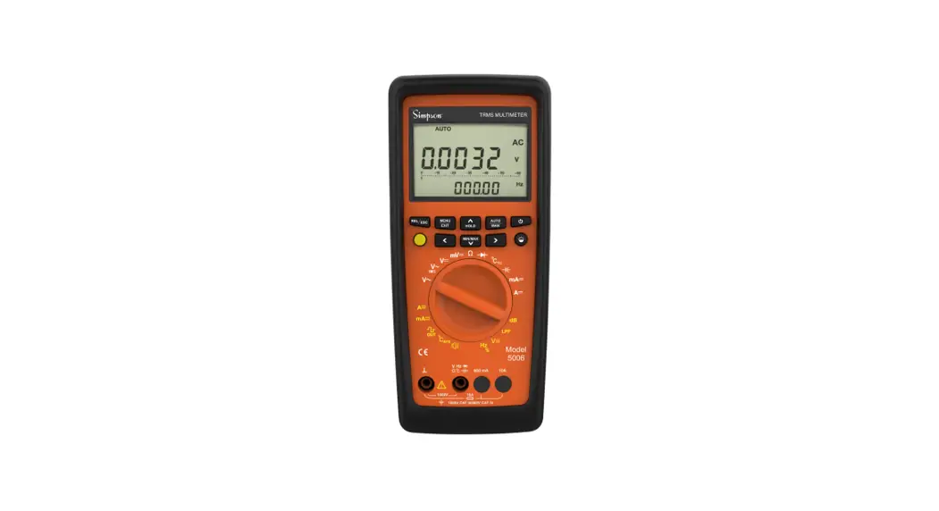
![]() 5002, 5003, 5005, 5006 Digital Portable Multimeter
5002, 5003, 5005, 5006 Digital Portable Multimeter
Owner’s Manual
Simpson 5002 5003 5005 5006 series of new multimeters is made for professional use that offers safety, high resolution, large range count, reliability, ruggedness, a complete tool for test automation and is equipped with more than 30 different measuring functions.
Special Features
- True RMS Digital Multimeter
- Data logger & View function (up to 32000 readings)
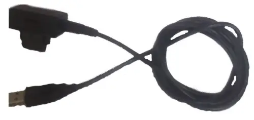
- Plug and Play USB connectivity with PC
- 100kHz bandwidth for voltage measurement
- 1kHz Low Pass Filter mode
- GO-NO-GO function
- VAC with 1MOhm impedance 4-20mA/0-20mA scale type measurement
- Single fuse for mA & A
- Adjustable square wave output
- Temperature measurement with J, K, Pt100 & Pt1000 sensors
- External power adapter for long hours of measurements
- Selectable clamp ratio for current measurement
- Conductance Measurement
- Frequency/Time Period Measurement
Application
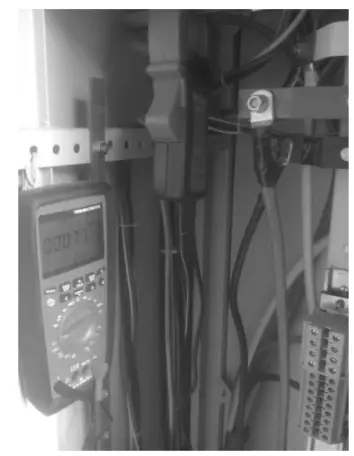
Low input impedance (Ri = 1MΩ)
Trouble shooting a branch circuit with dead or disconnected circuit is made easy with VAC1M. Low impedance VAC1M measurement helps eliminating error readings resulting from ghost voltages caused by long wires that share a common conduit
Single fuse(16A)
Instrument contains a single fuse of 16A common for all the ranges of current from 600μA to 10A AC/DC as compared to the two fuses in traditional DMMs. This eliminates the accidental blowing of 1.6A fuse due to operator’s error when higher current is applied in lower ranges
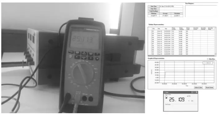
Tool for automation, USB 2.0 Interface
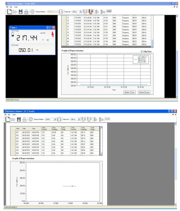
With ready to use communication protocol and plug and play USB 2.0 add-on device, one can easily automate his test system. The extensive data capturing and analysis is possible with DMM software. With vast functionality and editable report settings DMM software is a real help for easy report generation and analysis of a device under test.
Square Wave Output
A square wave output can be generated from the DMM with the user selectable frequency and adjustable duty cycle. This can be used as baud rate generator, to check flow meters, to test frequency counters, accelerometer and frequency transmitter. It can also be used as audio signal in audio signal testing.
Current measurement with clamp sensor
Measurement with various clamp sensors is possible, which helps in accurate measurement of current from 60mA to 6000A without interrupting the circuit. The measured current is automatically calculated from the selected clamp ratio.
Low pass filter(LPF) in VAC10MΩ & VAC1MΩ
A selectable 1kHz low pass filter offers advanced variable frequency drive filtering to help you accurately analyze nontraditional sine waves and noisy signals.
In LPF mode DMM rejects all high frequency noise making it suitable for making measurements on inverters and high frequency drives.
True RMS measurement with high crest factors
Accurate true RMS measurement of distorted waveform with crest factor CF between 1 to 10.
Data Logging
DMM 5005/5006 offers continuous data logging of up to 32000 readings with real time stamping. Log rate is adjustable from as low as 0.1 sec to as high as 1hr.
Adjustable Beep Level
With Beep level setting, the limit for continuity can be adjusted from 10Ω to 90Ω depending upon application.
Separate fuse compartment
Easier access to fuse when replacing the blown fuse.
Auto Power OFF with adjustable timing
Flexibility to adjust “Auto off ” period from 5 minutes to 60 minutes.
60mv & 600mV DC & ACDC
This helps in accurate measurement of low output voltages <600mV from sensors & transmitters. High frequency low voltage signal from RF transmitters can also be measured. Signal as low as 0.001mV can be measured accurately.
Min / Max / Avg measurement
Min/Max/Avg function records the minimum, maximum and average of all the readings applied since its activation. With dual display it makes it even flexible for the user to keep the trace of the applied readings while viewing Min/Max/Avg readings. The average reading is useful for smoothing out unstable inputs,& verifying circuit performance.
Dedicated keys for easy navigation
Dedicated navigation keys makes scrolling through menu and setting of parameters easy & comfortable.
External Power Adapter (DC Jack)
The external power supply adapter helps in conserving battery while performing long hours of measurements. When DC jack is connected batteries inside DMM are electronically disconnected, and reconnected in absence of mains, hence there is no need of removing the battery when using the power adapter.
100kHz Bandwidth
Alternating voltages with frequencies up to 100kHz can be measured accurately. This is useful while analyzing high frequency analog signals.
Self battery voltage measurement
Capable of measuring self battery voltage.
Room temperature measurement
Room temperature can be sensed and measured without any external sensor. The same is used as internal reference temperature in thermocouple based temperature measurements
Fully programmable GO NO-GO
The Go – NoGo function gives an indication through a buzzer for the applied input lying inside or outside the set band. The values for low limit, high limit and buzzer condition can be easily set through NoGo function in menu settings. Once the NoGo function is set, user can get busy doing other activities in the vicinity of the meter, whenever the condition is met it will be indicated by a buzzer. It eliminates the need of operator to continuously monitor the display.
View Function
Data logged on meter can be viewed directly on the meter itself, hence the data analysis is also possible without a PC based software. However for graphical and large data analysis PC based software can be used.
Dangerous Contact Voltage Indication
Presence of hazardous voltage (>35Vrms 50/60Hz and 50Vdc) at the contact terminal are indicated on display. This is very useful while performing measurements in the circuit which takes longer time to discharge its capacitors, or where unexpected danger voltage are present.
Model Wise Functional Overview
| Functions/Features | 5002 | 5003 | 5005 | 5006 |
| Voltage VDC (Ri>9MΩ) | • | • | • | • |
| Voltage VAC TRMS (Ri>9MΩ ) | • | • | • | • |
| Voltage LoZ VAC TRMS (Ri=1MΩ ) | • | • | • | |
| Voltage VAC TRMS (Ri>9MΩ) LPF 1kHz | • | • | • | |
| Voltage LoZ VAC TRMS (Ri=1MΩ) LPF 1kHz | • | • | • | |
| Voltage VACDC (Ri>9MΩ) | • | • | • | • |
| High impedance, high bandwidth mV measurement | 600mV | 60mV/600mV | 60mV/600mV | 60mV/600mV |
| Bandwidth VAC & mV ACDC | 10kHz | 10kHz | 10kHz | 100 kHz |
| Frequency Measurement | • | • | ||
| Duty cycle % | ||||
| Voltage level measurement dB, dBu, dBm | • | • | • | |
| Resistance | • | • | • | • |
| Conductance measurement | • | • | • | • |
| Continuity test (I const = 1 mA) | • | • | • | • |
| Diode measurement (I const = 1 mA) | • | • | • | • |
| Temperature measurement (TYP J,TYP K) | • | • | • | |
| Temperature measurement (PT100,PT1000) | • | • | • | |
| Capacitance measurement | • | • | ||
| Current ADC | 600mA | 6 A/16 A (20 A) | 600 μ A/ 6 m A 60mA/600mA 6A/10A(16 A) | 600 μ A/ 6 m A 60mA/600mA 6A/10A(16 A) |
| Current AAC+DC TRMS | ||||
| Current AAC TRMS | ||||
| Bandwidth @AAC+DC or AAC 10 kHz | • | • | • | • |
| Measurement with Clamp Sensor | • | • | • | • |
| Data Logging / Viewing Function | • | • | ||
| Protective rubber holster | • | • | • | • |
| Fuse 16A/ 1000V | 1.6A | • | • | |
| 0-20mA/ 4-20mApercentage scale | • | • | ||
| Square wave Out | • | • | ||
| Self battery voltage measurement | • | • | • | • |
| MIN/MAX/AVG and Auto Hold Functions | • | • | • | • |
| Dangerous contact voltage indication | • | • | • | • |
| REL/Zero function | • | • | • | • |
| USB IR-interface | Optional | |||
| External power supply adapter | ||||
| External power supply adapter | 1000 V CAT III 600 V CAT IV | 1000 V CAT I 600V CAT II | 1000 V CAT III 600 V CAT IV | 1000 V CAT III 600 V CAT IV |
Environmental Condition
| Operating temperature | -10 to +50°C, 14°F to 122°F |
| Storage temperature | – 25 to +70°C, -13°F to 158°F |
| Relative humidity | < 75% non condensing. |
| IP | I. P 50 for Housing, IP20 for terminals. |
| Altitude | Up to 2000 m |
Technical Specification
Voltage
Measurement Function | Measuring Range | Resolution | Input Impe dance | Intrinsic Uncertainty under Reference Condition ±(…% of the rdg.+…Digits) | Overload Capacity 2) | |||
| DC 7 | AC 1) 3) | ACDC 1) 3) | Value | Time | ||||
| V | 6V | 100µV | >9 MΩ | 0 .05 + 5 | 0 .5 + 9 | 1 + 30 | 1000 V DC/ AC RMS Sine | Continuous |
| 60 V | 1mV | 0 .05 + 5 | ||||||
| 600 V | 10 mV | 0 .05 + 9 | ||||||
| 1000 V | 100 mV | 0 .09 + 10 | ||||||
| mV | 60 mV | 1 µV | >10 MΩ | 0 .09 + 15 | – | 1 + 30 | Max10 s | |
| 600 mV | 10 µV | 0 .09 + 15 | ||||||
| Influence Quantity | Range of Influence | Range | Accuracy | |||||
| Simpson 5006 | Others 2) | |||||||
| Frequency 6) 9) | >15 Hz… 45 Hz | 60 mV~5), 600 mV~ | 3 +30 | |||||
| >65 Hz… 100 kHz | ||||||||
| >15 Hz… 45 Hz | 6 V, 60V, 600 V~ | 2 +9 | 3 +9 | |||||
| > 65 Hz… 1 kHz | 1 +9 | 3 +9 | ||||||
| >1 kHz…..20 kHz | 3 +9 | 4 +9 10) | ||||||
| >20 kHz….100kHz 8) | 3 .5 +30 | |||||||
| >15 Hz… 45 Hz | 1000 V~ | 2 +9 | 3 +9 | |||||
| > 65 Hz… 1 kHz | 2 +9 | 3 +9 | ||||||
| >1 kHz…..10 kHz | 3 +30 | |||||||
| 1 ) Specified Accuracy is valid as of 3% of the measuring range. With Short- circuited test probes: residual value of 1 to 30 d at zero point due to the TRMS converter. | ||||||||
| 2 ) At 0°C to 40°C (Accuracy Range) | ||||||||
| 3 ) In VAC measurement, Frequency will be shown above 10% of the present range, except for 1000V & 60mV range i.e. 25% & 50% respectively. | ||||||||
| 4 ) Frequency Influence upto 10kHz. | ||||||||
| 5 ) Frequency response up to 50 kHz | ||||||||
| 6 ) Frequency response is valid from 10% to 100% of range | ||||||||
| 7 ) With Zero Balancing | ||||||||
| 8 ) Frequency response up to 100 kHz, for greater than 50 kHz plus 2.5% | ||||||||
| 9 ) Overload capacity of the voltage measurement input: power Limiting: Frequency x Voltage Max : 6×10 V xHz for V>100V | ||||||||
| 10 ) Frequency response greater than 2 kHz plus 2.5% | ||||||||
Frequency, Duty Cycle
| Measurement Function | Measuring Range | Frequency | Intrinsic Uncertainty ±(% of the rdg. + .Digits) | Overload Capacity 1) | |
| Value | Time | ||||
| Hz5) | 600Hz, 6kHz, 60kHz, 600kHz, 114-1z | fmin2): 6Hz | 0.05 +5 | 1000 V DC/AC RMS Sine | Max 10 s |
| Hz(V)3) | 10Hz…..100kHz | 0.1 +54) | |||
| Duty Cycle (%) | 2.0…98% | 151-1z …. 1 kHz | 0.1 R +5 d | ||
| 5.0…98% | …. 10 kHz | 0.2 R per kHz+ 5d | |||
| 10…90% | …. 50kHz | 0.5 R per kHz+ 5d | |||
| 1) At 0°C to 40°C (Accuracy Range) | |||||
| 2) Lowest measurable frequency for square measuring signals symmetrical to the zero point ( ±5V). | |||||
| 3) Overload capacity of the voltage measurement input : Power limiting: Frequency x voltage max : 6×10 Vx Hz for U> 100V. | |||||
| 4) Input sensitivity, sinusoidal signal, 10% to 100% of the measuring range | |||||
| 5) At input ±5Vrms, Square wave, Bipolar inputs. | |||||
| R= Range d= digit | |||||
Current
| Measurement Function | Measuring Range | Resolution | Voltage Drop Approx. | Intrinsic Uncertainty under Reference Condition ± (…% of the rdg.+…Digits) | Overload 32) Capacity | |||||
| DC 4) | AC 1) | ACDC 1) | Value | Time | ||||||
| mA | 600 μA | 10 nA | 60 mV | 05 + 15 | 1 +10 | 15 + 10 | 0.7A | Continuous | ||
| 6 mA | 100 nA | 60 mV | 0.5 + 5 | 1+10 | 15 + 10 | |||||
| 60 mA | 1 µA | 60 mV | 01 + 5 | 1 + 10 | 1.5 + 10 | |||||
| 600 mA | 10 μA | 60 mV | 02 + 5 | 1 + 10 | 15 + 10 | |||||
| A | 6A | 100µA | 60 mV | 0.9 + 10 | 1 +10 | 15 + 10 | 10 A =5 min 3) | |||
| 10A | 1 mA | 300 mV | 0.9 + 10 | 1+10 | 15 + 10 | |||||
| Influence Quantity | Range of Influence | Range | Accuracy | |||||||
| Simpson 5006 ±(…% of the rdg +…Digits) | Others | |||||||||
| Frequency 5) | >15 Hz ….45 Hz | 600µA. 10A | 3+10 | |||||||
| >16 Hz….10 kHz | ||||||||||
| 1) Specified Accuracy is valid as of 3% of the measuring range. With Short-circuited test probes: residual value of 1 to 30 d at zero point due to the TRMS converter. | ||||||||||
| 2) At 0°C to 40°C (Accuracy Range) | ||||||||||
| 3) Off time 30 min and TA= 40°C | ||||||||||
| 4) With Zero Balancing | ||||||||||
| 5) Frequency response is valid from 10% to 100% of range | ||||||||||
Resistance, Diode, Continuity
| Measurement Function | Measuring Range 4) | Resolution | Open Ckt. Voltage | Meas. curr. @ range limit | Intrinsic Uncertainty ±(…% of the rdg +…Digits) | Overload Capacity 2) | |
| Value | Time | ||||||
| Ω 1) | 600 Ω | 10mΩ | <1.4V | Approx. 300 μA | 0.1 + 10 | 1000 V DC/ AC RMS Sine | Max 10 s |
| 6 k Ω | 100mΩ | Approx. 250 μA | 0.1 + 10 | ||||
| 60k Ω | 1Ω | Approx. 100 μA | 0.1 + 10 | ||||
| 600kΩ | 10 Ω | Approx. 12 μA | 0.5 + 10 | ||||
| 6MΩ | 100 Ω | Approx. 1.2 μA | 1 + 10 | ||||
| 60MΩ | 10k Ω | Approx. 125 nA | 5 + 10 | ||||
| Continuity | 600 Ω | – | Appx. 8V | Approx. 1 mA | 3 + 5 | ||
| Diode 1) | 6.0V 3) | – | Appx. 8V | Approx. 1 mA | 0.5 + 5 | ||
| 1) Measurement of Resistance, Diode will be more accurate after removal from device under test | |||||||
| 2) At 0°C to 40°C (AccuracyRange) | |||||||
| 3) Displays up to max6.0 V, “OL” in excess of 6.0V. | |||||||
| 4) With Zero Balancing | |||||||
Temperature
| Measurement Function | Measuring Range | Intrinsic Uncertainty ±(…% of the rdg +-Digits) | Overload Capacity 1) | ||
| Value | Time | ||||
| Temperature °C/ °F | Pt 100 | -200°C. +850°C/-328°F to 1562°F | 2) 0.3 + 15 | 1000 V DC/AC R MS Sine | Max 10s |
| Pt1000 | -150°C..+850°C -238°F to 1562°F | 0.3 + 15 2) | |||
| TC K | -200°C..+1372°C -328°F to 2501.6°1– | 1 % +20 2) | |||
| TC J | -210°C..+1200°C -346°F to 2192°F | 1 % +20 2) | |||
| 1 ) At 0°C to 4 0°C (Accuracy Range) | |||||
| 2) Plus Sensor Deviation | |||||
Capacitance
| Measurement Function | Measuring Range | Resolution | VO Max | Intrinsic Uncertainty ± (% of the rdg +Digits) | Overload Capacity 1) 2) | |
| Value | Time | |||||
| F 3) 4) | 1 0 n F | 1 0 p F | 0 .7 V | 1 +1 0 2) | 1000VDC/AC RMS Sine | Max 10 s |
| 1 0 0 n F | 1 0 0 p F | 1 + 6 2) | ||||
| 1 µ F | 1 n F | 1 + 6 2) | ||||
| 1 0 µ F | 1 0 n F | 1 + 6 2) | ||||
| 1 0 0 µ F | 1 0 0 n F | 5 + 6 2) | ||||
| 1 0 0 0 µ F | 1 µ F | 5 + 6 2) | ||||
| 1 ) At 0 °C to 4 0 °C (Accuracy Range) | ||||||
| 2 ) Applies to measurements at film capacitors and battery operated : | ||||||
| 3 ) Measurement of Capacitance will be more accurate after removal from device undertest | ||||||
| 4 ) With Zero Balancing | ||||||
Square Wave Out
| Output | Range | Accuracy |
| Frequency | 30Hz – 10kHz | 0.1% x output frequency + 2 counts of DMM display |
| Duty Cycle | 10% – 100% 2) | 0.2% of Full scale 1) |
| Amplitude | Fixed -3.15 to 3.15V | ±0.4V |
| 1) For signal greater than 1kHz, add 0.2% per kHz to the accuracy | ||
| 2) In Multiple of 10 | ||
Influence Error
| Influence Quantity | Range of Influence | Measured Quantity/ Measuring Range 1) | Variation ± (….%of rdg +. digits)/10k |
| Temperature | -10ºC to 21ºC & +25 °C to 50°C | VDC | 0.2 + 20 |
| V~, VACDC | 0.4 + 10 | ||
| 600Ω to 600 kΩ | 0.5 + 10 | ||
| > 600 kΩ | 1 + 10 | ||
| mA/ADC | 0.6 + 10 | ||
| mA/AAC, ACDC | 0.8 + 10 | ||
| 10nF…10µF | 1 + 5 | ||
| 100µF…1000µF | 1.5+10 | ||
| Hz,% | 0.2 + 10 | ||
| ºC/ºFpt100/pt1000 | 0.5 + 10 | ||
| ºC/ºF thermocouple K/J | 0.2 + 10 | ||
| Relative humidity | 75% 3Days Meter off | V, A, Hz, %, Diode F,Ω | 1 × intrinsic error |
| Battery voltage | 1.8 to 3.6V | V, A, Hz, %, Diode, F,Ω | 1 × intrinsic error |
| 1) With Zero Balancing | |||
Reference Condition for Accuracy
| Reference Temperature | 23°C ± 1K, 73.4°F ± 1K |
| Relative Humidity | 45%…55% RH |
| Waveform of measured quantity | Sinusoidal |
| Input frequency | 45…65 Hz |
| Battery Voltage | 3 V ± 0.1 V |
Influence Quantity
| Influence Quantity | Range of Influence | Measuring Ranges | Attenuation |
| Common Mode interference voltage | Noise quantity max. 1000 V dc | V dc | > 120 dB |
| Noise quantity max. 1000 V ~ 50-60 HZ sinusoidal | 6.0 V~, 60 V~ | >80 dB | |
| 600 V~ | > 70 dB | ||
| 1000 V~ | > 60 dB | ||
| Normal Mode interference ratio | Noise quantity V ~ Value of the measuring range at a time Max. 1000V~, 50Hz, 60Hz Sinusoidal | V dc | > 50dB |
| Noise quantity max. 1000 V dc | V~ | >110dB |
Applicable Regulations & Standards
| EMC Immunity | IEC 61326-1:2012, Table A.1 |
| Immunity | IEC 61000-4-2 : 8 KV atmosphere discharge, 4 KV contact discharge |
| IEC 61000-4-3 : 3 V/m | |
| Safety | IEC 61010-1-2010 |
| IP for water & dust | IEC 60529 : IP 50 For Instrument and IP20 for socket |
| Pollution degree: | 2 |
| Installation category: | 1000 V CATIII / 600 V CATIV, 600V CATII for DMM 5003 |
| High Voltage Test | 7.4 kV (IEC 61010-1-2010), 3.5kV For DMM 5003 |
| Test & Procedure | IS 13875 |
Battery
| Battery Voltage | 2 X 1.5 V Cells (LR6 Battery) |
| Battery type | Alkaline manganese cells. |
| Battery Life | Appx. 100 Hrs. (Backlight off) |
| Battery test | Automatic display of |
Mechanical Design
| Housing | PC ABS |
| Dimension | 200 x 91 x 54 mm |
| Weight | Approx. 0.5 kg with batteries |
Crest Factor
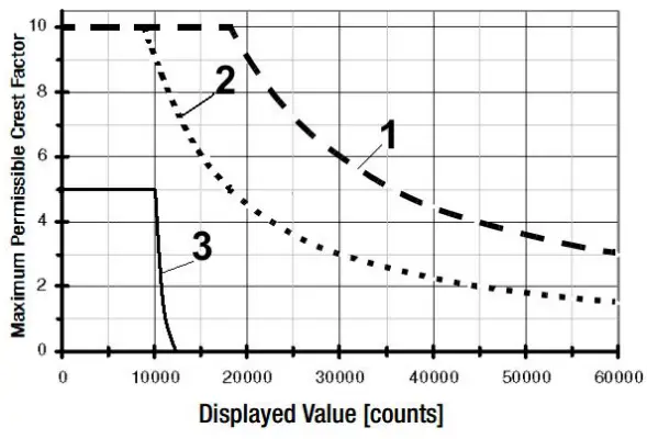
Additional error caused by signal’s crest factor: 1 < CF < 3: 1% R+ 30D
3 < CF < 10: 3% R
Curve 1 : Range from 0.06V to 60V, 0.6mA to 60mA, 6A
Curve 2 : Range 600V/600mA
Curve 3 : Range 1000V/10A
Note: With Unknown Waveform (CF >2), measurement should be made with manual range selection.
R = Reading
D = Digit
Internal Clock
| Time Format | dd. MM. yy hh. mm. ss |
| Resolution | 1 s |
| Accuracy | +1min. per month |
| Temperature Influence | 50 ppm/K |
Display
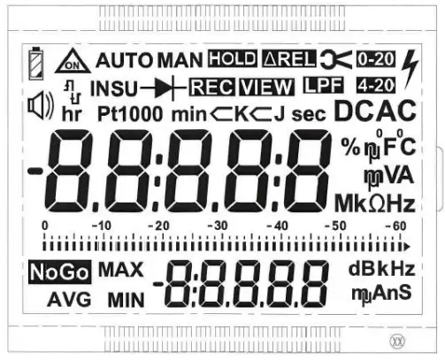
LCD display field 67 mm X 54 mm with digital display, analog scale and with display of measurement unit, and Various special functions.
Analog
| Display: | LCD scale with bar graph or pointer, depending on the selected parameter setting |
| Scaling: | 2 bar/pointer corresponds to 2500 counts at the digital display |
| Over range Display (Digital): | By triangle “ |
| Polarity Display: | With automatic switching |
| Sample rate (Digital): | 10 measurements/sec and display refresh |
Digital
| Display: | 7-segment characters |
| Character Height: | Main Display – 12.88mm Sub Display – 7.37mm |
| Resolution: | 60,000 counts |
| Overflow Display: | “OL” is displayed |
| Polarity Display: | “-” (minus) is displayed if plus pole is connected to “ ⊥” |
| Measuring Rate: | 10 measurement/sec with the Min-Max function except for the capacitance, frequency and duty cycle measuring Function |
| Refresh Rate: | 4 times/sec |
| Number of Digits: | 5 |
Fuse
| Fuse | FF (UR) 16 A/ 1000 V AC/DC; 10 mm x 38 mm ( Simpson 5005 & 5006) |
| FF (UR) 1.6 A/ 1000 V AC/DC ; 6.3 mm x 32 mm ( Simpson 5002) | |
| Switching Capacity | 30 kA at 1000 V AC/DC (Simpson 5005 & 5006) |
| 10 kA at 1000 V AC/DC (Simpson 5002) |
Accessories For Operation at a PC
Interface Adapter For USB Communication
| Communication: | Bi-Directional |
| Baud Rate: | 9600 |
| Data Bit: | 8 |
| Stop Bit: | 1 |
| Flow Control: | None |
A CD ROM is included which contains current drivers for Windows operating systems, Installation Guide, Datalogger User Manual and Datalogger Setup File.
Scope of Supply
| Model Name | Scope of Supply |
| Simpson 5002 Simpson 5003 Simpson 5005 Simpson 5006 | 1. Digital Meter |
| 2. Cable Set | |
| 3. Protective Case | |
| 4. Battery | |
| 5. Operating Manual | |
| 6. Test Certificate | |
| OPTIONAL ACCESSORIES | |
| 1. External Power Supply Adapter | |
| 2. USB Interface Adapter + Software CD | |
![]() Simpson Electric Company
Simpson Electric Company
520 Simpson Avenue
Lac Du Flambeau, WI 54538-0099 (USA)
Web: www.simpsonelectric.com
Contact: +1 715-588-3311
Revision 2022/10


