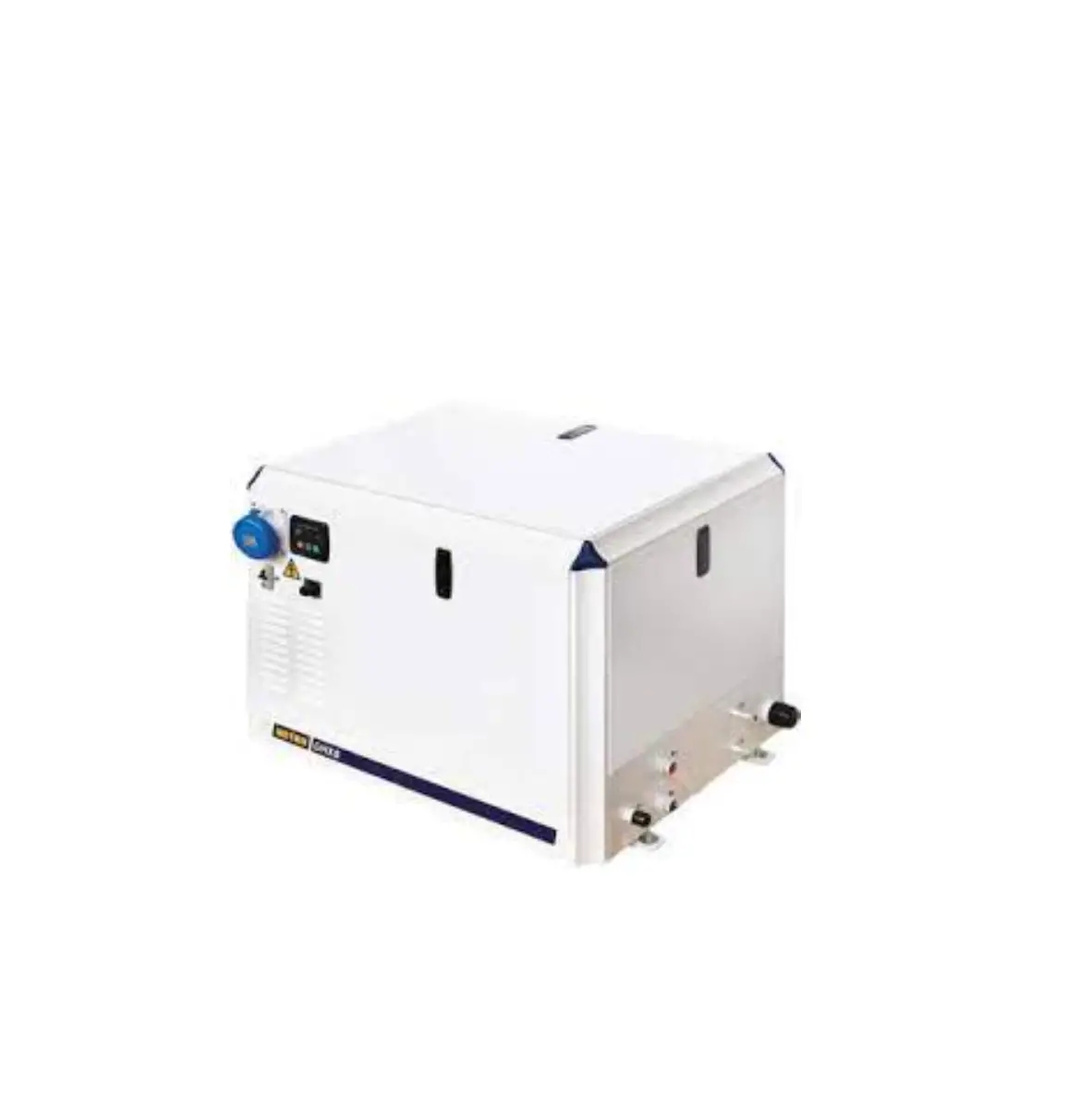
vetus GHX GLX Generator Set
Safety Information
Warning indications
The following warning indications are used in this manual in the context of safety:
![]() DANGER Indicates that great potential danger exists that can lead to serious injury or death.
DANGER Indicates that great potential danger exists that can lead to serious injury or death.
![]() WARNING Indicates that a potential danger that can lead to injury exists.
WARNING Indicates that a potential danger that can lead to injury exists.
![]() CAUTION Indicates that the usage procedures, actions etc. concerned can result in serious damage to property. Some CAUTION indications also advise that a potential danger exists that can lead to serious injury or death.
CAUTION Indicates that the usage procedures, actions etc. concerned can result in serious damage to property. Some CAUTION indications also advise that a potential danger exists that can lead to serious injury or death.
![]() IMPORTANT Emphasizes important procedures, circumstances etc.
IMPORTANT Emphasizes important procedures, circumstances etc.
Symbols
![]() Indicates that the relevant procedure must be carried out.
Indicates that the relevant procedure must be carried out.
![]() Indicates that a particular action is forbidden.
Indicates that a particular action is forbidden.
Pass the safety precautions on to other people who will use the generator set.
General rules and laws concerning safety and accident prevention must always be observed
Safety rules
- The manufacturer cannot be held responsible for any damage resulting from misuse of the generator set / engine, from the failure to follow the indications contained in this manual and for every tampering with or change made without the manufacturer’ s authorization.
- Refer only to a technician staff, with precise technical skills, specific abilities and experiences. The lack of these requirements could provoke damages to people’s safety.
- Use the generator set only for the task authorized by the manufacturer, do not manipulate anything to obtain different performances.
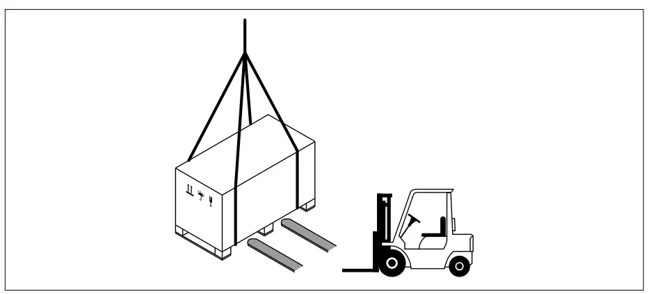
- When lift and during the transport of unpacked generator set use means of appropriate load capacity.
- When lift packed generator set pay attention on load indication printed on box!
- During the installation the installer had to follow the designer’s indications. Do not make changes to the generator / engine components for any reason.
- Do not keep using the generator set if anomalies are detected.
- In case of anomaly, stop immediately the engine or reduce the load as much as possible. Start again only when normal condition are restored.
- Replace only original spare parts. Use oils and greases recommended by manufacturer.
- Stop the engine and switch of the power with the main switch (switches ) before working on the electrical system.
- Never start the generator set without air filter, dirt could damage the engine.
- Don’t smoke near the starter battery ! The battery release flammable gases. Wrong battery connection could provoke sparks and explosion.
- Never confuse the plus and minus terminal when fittings the batteries.
- Use correct protection (clothes etc.) during maintenance operations!
- Always close the raw water inlet valve when you dismount the coolant system!
- Never use starter spray or similar. To prevent the risk of explosion in the air inlet pipe.
- Avoid to opening the coolant filler cap when the engine is hot. Steam or hot coolant can spray out, and built up pressure will be lost. Open the filler cap slowly and release the overpressure if the filler cap must be opened.
- Hot oil can cause burnt injuries. Avoid skin contact with hot oil. Make sure that the oil system is not pressurized before working on it. Never start the engine with the oil filter cap removed!
- During maintenance operation make sure that the engine room is well ventilated.
- Do not throw away any polluting material. Follow the local rules of legislation.
- If you wash the engine with high pressure wash, observe the following:
- never point the jet of water at seals, rubber hoses or electrical components.
- never use high pressure function when washing the engine.
- Use the correct fuel, see the fuel indications in owners manual.
- Keep the equipment as much efficient as possible and carry out the scheduled maintenance operations established with the manufacturer.
![]() IMPORTANT
IMPORTANT
This installation manual has been published by VETUS to aid the boat manufacturer involved in the application and installation of the products described herein.
It is assumed that these personnel are familiar with marine product application and the installation procedures of these products, or like or similar products manufactured and marketed by VETUS. furthermore, it is assumed that they are familiar with, if not trained in, the recommended installation procedures of these products.
It is the responsibility of the purchaser (whether boat builder or dealer) of a VETUS generator set to select the appropriate package for a given installation. Making such a selection requires knowledge of the boat, including intended use, intended duty cycle all of which is in the exclusive possession of the purchaser.
All information, illustrations, and specifications contained in this manual are based on the latest product information available at time of publication. Vetus reserves the right to make changes at any time without obligation.
Engine lifting
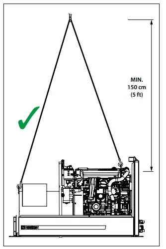
![]() WARNING Handle the unpacked unit with care!
WARNING Handle the unpacked unit with care!
When you install the generator set on the boat after opening the packaging always follow the hoist instructions below.
Preferably use a spacer rod as shown in the drawing lift the engine.
Assure that the spacer rod is in ‘good condition‘ and strong enough to withstand the weight.
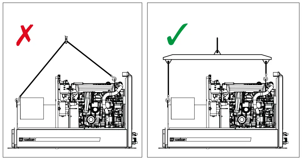
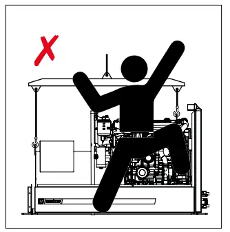
WARNING The lifting hooks are engineered only to lift the generator set without any extra weights!
Introduction
The reliability of the total generator set is entirely dependent on the quality of the installation. Nearly all problems are caused by faults or inaccuracies which occur during the installation. It is therefore of utmost importance to follow and check the points mentioned in the manual.
Generator set storage, before use
If the generator set is stored for a prolonged period, check the possible conditions of conservation in relation to the storage environment and the type of packaging.
The engine is supplied with a protection treatment which is valid for 6 months from delivery date.
- Check for the coolant (coolant circuit). The engine supplied with a mixture to withstand storage temperature of -15 °C (5 °F).
![]() ATTENTION The raw water circuit could contain engine test bed water. Drain completely the raw water circuit if the storage temperature is lower than 0°C (32°F).
ATTENTION The raw water circuit could contain engine test bed water. Drain completely the raw water circuit if the storage temperature is lower than 0°C (32°F).
- Verify the packages integrity.
- Humidity and salt corrosion could damages the engine and/or generator during their storage.
First engine start
- Read the owner’s manual.
- Verify the fuel feed line for possible leaks. Take care to avoid restrictions in the fuel line pipes.
- Check and verify the electrical connections.
![]() IMPORTANT Wrong connection of positive and negative from battery could provoke short circuit and damage the engine.
IMPORTANT Wrong connection of positive and negative from battery could provoke short circuit and damage the engine.
![]() IMPORTANT Wrong connection of generator terminals could damage the generator.
IMPORTANT Wrong connection of generator terminals could damage the generator.
- Check the battery condition and state of charge.
- Check the raw water circuit, the connection and open the sea cock.
- Check the belt and belt tension.
- Check coolant level and oil level of engine, verify if fuel is available in the tank. Fuel tank must be clean!
- Start the engine, lets warm up the engine for few minutes without load.
- Verify for any leaks, verify the sea water pump, and verify the flush of water on exhaust system, verify that no warnings on the control panel are displayed.
![]() IMPORTANT If you hear a strange noise, or vibration of the engine is extreme or black smoke is coming out of the exhaust stop the engine immediately and ask for assistance.
IMPORTANT If you hear a strange noise, or vibration of the engine is extreme or black smoke is coming out of the exhaust stop the engine immediately and ask for assistance.
When the temperature of the engine stabilizes at a temperature higher than normal it might be necessary to bleed the coolant circuit.
Bleeding the coolant circuit:
- Switch off the engine of the generator set.
- Open the expansion tank cap to let the air escape.
- Add coolant or water to the coolant circuit if necessary.
- Close the cap.
- Start the engine and verify if the engine is running normal
Long engine storage – Inactivity
If the engine remains inactive for a period of time exceeding 6 months, you need to protect it from oxidation and breakdowns in accordance with the following instructions:
- Drain off the water from the fuel system and fill the fuel tank.
- Make sure that the engine fuel system is filled with a fuel mixture with protective properties.
- Flush out the raw water circuit with fresh water and if necessary fill with antifreeze. Clean the heat exchanger if necessary.
- Make sure that the cooling system is filled with a suitable anti-freeze.
- Let the engine run for 15 minutes without load; stop the engine and change the oil filter and the engine oil.
- Put oil (according to the specifications into the oil sump until the oil sump reaches at least ‘Min’ on the oil dipstick.
Oil 15 W40, API: CF4, CG4, CH4, CI4 or ACEA: A3/B3, A3/B4, E7
For example: Vetus Marine Diesel Engine Oil 15 W40
Shell Rimula R4 15W40
- Disconnect the battery cables, charge the batteries if necessary and grease the battery terminals.
After a period of inactivity, it is necessary to carry out a some maintenance work before starting the engine again to ensure its efficiency conditions.
- Check the battery charge level conditions. Assure that the battery voltage is over 12.5 V.
- Make sure the electric contacts are intact. Assure the correct electrical connections.
- Carry out the engine diagnosis.
- Check the oil level-conditions, and if necessary, top- up or replace.
- Verify and if necessary replace the oil filter.
- Check the coolant level an mixture, and if necessary top – up.
- Replace / Clean the fuel filter.
- Clean the air filter.
- Verify the belts status and tighteners.
- Verify the integrity of the sea water pump impeller.
- Check the integrity of zinc anodes, is present.
- Verify and if is necessary grease: starter pinion.
- Start the engine and run without load for few minutes.
- If no anomalies bring the engine to its operating temperature, 70 – 80 °C (158 – 176 °F). Verify that there is no air in the coolant circuit – bleed the air from coolant circuit if necessary.
- Turn off the engine and check again the engine oil level and coolant level.
- Verify for tightening.
Generator set requirements
Generator Set Compartment
![]() IMPORTANT Boating standards and legislation must be adhered to when constructing the generator set compartment
IMPORTANT Boating standards and legislation must be adhered to when constructing the generator set compartment
Care must be exercised in the design and construction of the generator set compartment. Seams must be located so that any rain water that may leak through the seams is directed away from the air intake system. Water that runs onto the air intake may enter the engine and/or generator and cause serious damage to internal engine and/or generator parts.
![]() IMPORTANT Vitus will not honors any warranty claim for engine damage as a result of water entry.
IMPORTANT Vitus will not honors any warranty claim for engine damage as a result of water entry.
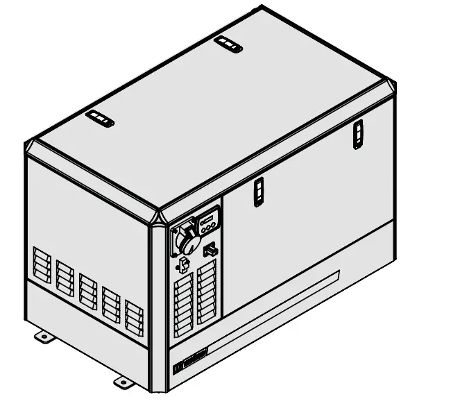
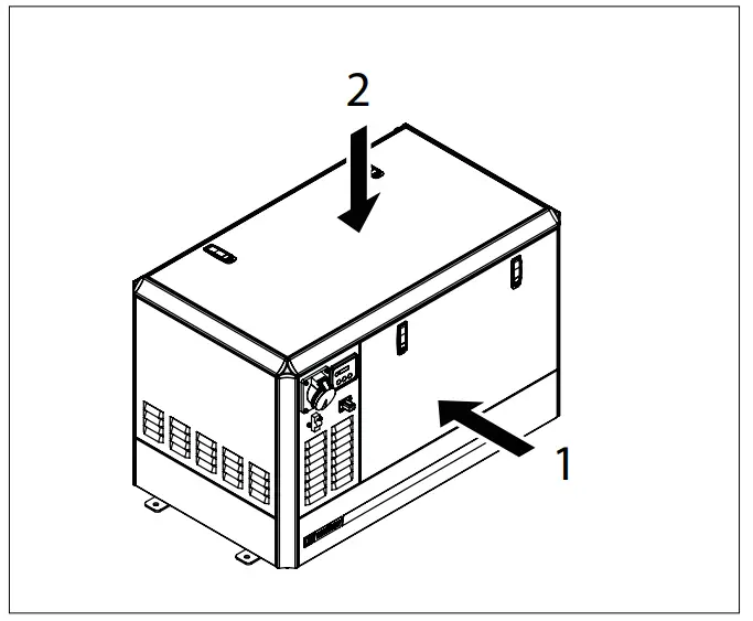
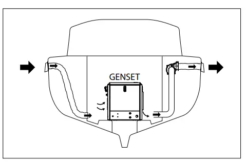
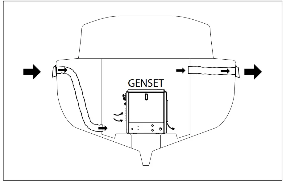
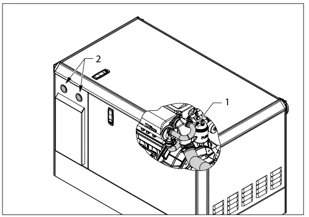
When selecting a location for the generator set take into consideration that there is sufficient room for carrying out maintenance work. Therefore the engine must be easily accessible on the service side (1).
For (re)filling of oil and coolant the upper side of the engine must be easily accessible (2).
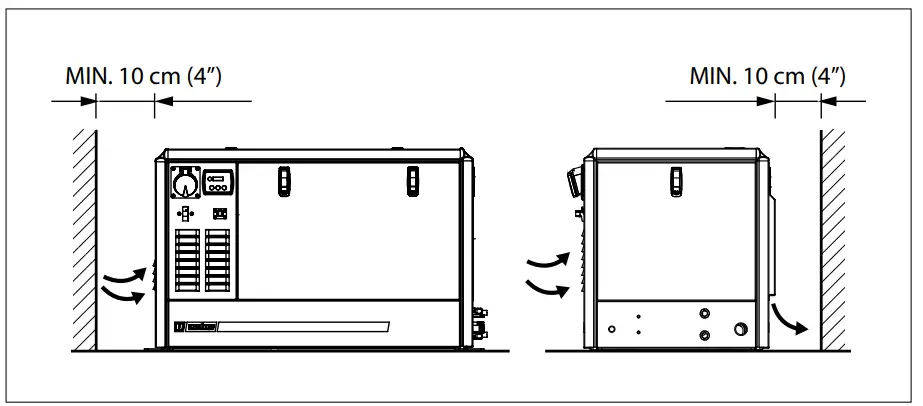
For ventilation and combustion air it is important to keep the housing at least 10 cm (4 in.) free of a bulkhead as per drawing.
Position the generator set as low as possible into the ship.
The generator set is already secured to the engine bed by means of flexible engine mounts. The feet (3) of the engine bed can be mounted directly to the ship.
Never connect the bed of the generator set directly to bulkheads or tank walls.
Generator Set Compartment Ventilation
This section does not cover the design of the ventilation system as it pertains to ventilation of fumes from the engine compartment. The requirements for ventilation of fumes varies considerably from one boat design to the next, as well as from country to country, and therefore, the boat manufacturer is responsible for ensuring their application is in compliance with the appropriate industry regulations and standards.
According to boating standards and legislation the engine compartment ventilation system has multiple tasks. Included the following:
- To supply the engine with combustion air.
- To maintain a low temperature in the engine compartment
Fresh air should enter the engine compartment as low as possible and the heated air should be discharged from the highest point.
If a separate air duct (or similar) is used to provide engine compartment ventilation, or additional ventilation, care must be taken to prevent seawater and spray from entering it.
![]() WARNING Ventilating air is required to clear the bilges, as well as the compartment in which the engine is located, of potentially toxic and flammable vapours.
WARNING Ventilating air is required to clear the bilges, as well as the compartment in which the engine is located, of potentially toxic and flammable vapours.
Intake air requirement
The generator set normally draw air from the engine room.
Engine compartments with natural draft ventilation must have vent openings of sufficient size and location to accomplish the tasks previously outlined, see table below for absolute minimum required area ventilation opening.
An ample supply of air within the temperature limits of the generator set and carry away heat from the generator set in the engine room is thus assured.
A ‘sealed’ engine compartment must have a good ventilation to maintain reasonable engine room temperatures. High temperature of intake air reduces engine performance and increases engine coolant temperatures. Air temperatures above 40 degrees C (104 degrees F) reduce the engine power by 1% for each 5.5 degree C (10 degree F) of rise. To minimise these effects the engine room temperature must not be more than 15 degrees C (30 degrees F) above the outside ambient air temperature.
Apply a combination of ventilators, blowers and air intake ducting to met the temperature limit.
In cases where it is impossible to met the above mentioned temperature limit with using natural ventilation connections are available, both for air inlet and air exhaust of the sound box. With these connections the generator set can be directly connected to air ducts.
Air inlets should be louvred to protect the engine room where appropriate the generator set from water spray. Even better is a cowl ventilator with dorado box located as high as possible.
The air inlet ducts should run to the bottom of the engine room to clear fumes from the bilges and to circulate fresh air..
Air outlets should be at the top of the engine room to remove the hottest air.
An engine room blower (optional) should be used as an extraction ventilator to remove air from the engine room. Such air intake should be positioned as low as possible.
![]() IMPORTANT The size of ventilation openings must be sufficient for both the generator set and the main propulsion engine(s) located in the same compartment.
IMPORTANT The size of ventilation openings must be sufficient for both the generator set and the main propulsion engine(s) located in the same compartment.
The combustion air requirement for the generator set is as shown in the table below:
| Generator set model | Combustion air flow | Ventilation opening | ||
| GHX 8 | 1.1 m3/min | ( 37 cu.ft/min ) | 58 cm2 | ( 9 sq.in. ) |
| GHX 9 | 1.3 m3/min | ( 44 cu.ft/min ) | 70 cm2 | ( 11 sq.in. ) |
| GHX 14 | 1.9 m3/min | ( 67 cu.ft/min ) | 105 cm2 | ( 16 sq.in. ) |
| GHX 17 | 2.2 m3/min | ( 78 cu.ft/min ) | 123 cm2 | ( 19 sq.in. ) |
| GHX 24 | 3.2 m3/min | ( 111 cu.ft/min ) | 175 cm2 | ( 27 sq.in. ) |
| GLX 6 | 0.8 m3/min | ( 30 cu.ft/min ) | 47 cm2 | ( 7 sq.in. ) |
| GLX 7 | 1.1 m3/min | ( 37 cu.ft/min ) | 58 cm2 | ( 9 sq.in. ) |
| GLX 14 | 1.9 m3/min | ( 67 cu.ft/min ) | 105 cm2 | ( 16 sq.in. ) |
| GLX 17 | 2.2 m3/min | ( 78 cu.ft/min ) | 123 cm2 | ( 19 sq.in. ) |
| GLX 20 | 2.6 m3/min | ( 93 cu.ft/min ) | 146 cm2 | ( 23 sq.in. ) |
| GLX 24 | 3.2 m3/min | ( 111 cu.ft/min ) | 175 cm2 | ( 27 sq.in. ) |
Fuel connection
Fuel Delivery System
![]() IMPORTANT Boating standards (CE-ABYC) and Coast Guard regulations must be adhered to when installing fuel delivery system.
IMPORTANT Boating standards (CE-ABYC) and Coast Guard regulations must be adhered to when installing fuel delivery system.
The main concern of a boat’s fuel system is safety; this must be achieved through a technically sound installation and constant inspection.
The fuel system, from the filler pipe to the fuel pump is the same, in principle, for all boats.
The fuel tank is an integrated component of the boat.
Fuel tanks can be made of (stainless) steel or of plastic.
Steel tanks should not be galvanised or painted inside. Condensation can occur when temperature changes; this water accumulates at the bottom of the tank.
The generator set itself is equipped with a fuel lift pump; therefore the tank can be installed at a lower level than the generator set. The maximum suction height is 1.50 m (5 ft).
Only a few points related to function and safety are listed here:
- All connections should be on the upper side of the tank.
- The drain plug at the lowest point on the tank serves to permit the removal of water and sediment.
- The filler tank pipe outer diameter should be at least 50 mm (2 in.).
- The tank breather pipe must have an inner diameter (I.D.) of at least 13 mm (1/2 in.) and must be fitted with a goose neck to prevent water from entering the tank.
- Diesel tanks shall be equipped with inspection hatch(es) having a suitable diameter of at least 120 mm at suitable position(s) for cleaning and inspection of the lowest part(s) of the tank. The hatch must remain accessible when the tank has been installed in the craft. The hatch(es) may be located on the top or side of the tank.
It is recommended that the exact route and length of the fuel lines be established at the first installation of the engine to prevent problems later in connecting them to the engine.
![]() ATTENTION!
ATTENTION!
All fuel lines must be well secured. The holes where the lines run through the bulkheads should be carefully rounded off, or protected with rubber grommets. This prevents damage to the lines from abrasion.
![]() ATTENTION! The max. fuel pump suction pressure head is around 1.5 m (60 inches) take care when install the fuel line.
ATTENTION! The max. fuel pump suction pressure head is around 1.5 m (60 inches) take care when install the fuel line.
![]() ATTENTION! Air leaks or narrow needs on fuel line could provoke engine stop.
ATTENTION! Air leaks or narrow needs on fuel line could provoke engine stop.
Fuel connections
The following, but not limited to the following, additional fuel connection related points, applying to all engines unless otherwise stated, must be considered.
- Fuel pickup should be at least 25 mm (1 in.) from the bottom of fuel tank, to prevent picking up impurities.
- The fuel lines (both supply- and return line) should be copper, tubing 8 mm (5/16 in.) outer diameter. The fuel lines can be plumbed to the flexible hoses mounted at the bed of the generator set.
- If the generator set is positioned at a higher level than the tank it is recommended to run the fuel return line to approx. 1 cm (3/8”) from the bottom of the tank so to prevent possible syphoning when the generator set is not running.
- A flexible fuel line must be used to connect fuel supply line to fuel inlet fitting on the generator set to absorb deflection when engine is running. Injection pump fuel return line must also have a flexible rubber hose segment.
- On Multi-Engine Diesel Installations: Use a separate tube for the fuel supply line and fuel return line, for each engine.
- Larger diameter (than previously specified) lines and fittings must be used on installations requiring long lines or numerous fittings.
- Fuel line(s) should be installed free of stress and firmly secured to prevent vibration and/or chafing.
- Sharp bends in fuel lines should be avoided.
Shut off valve
The generator set is equipped with a electrically operated shut off valve. But in the supply line, as close as possible to the tank, a shut off valve must be installed too.
Make sure the boat owners know the location and how to operate it.
Diesel fuel Pre-filter and fuel additives.
There is the possibility that contamination of diesel fuel and algae growth in the diesel fuel could block the lift pump resulting in poor performance.
![]() IMPORTANT The engine is provided with an element type fuel filter, but to help eliminate water and dirty it is recommended to use an additional 10 micron filter that has a water separator
IMPORTANT The engine is provided with an element type fuel filter, but to help eliminate water and dirty it is recommended to use an additional 10 micron filter that has a water separator
It is recommended to install an additional fuel filter equipped with a water separator before the fuel lift pump. We recommend a 10 micron, 190 l/h (42 Imp. gph, 50 US gph) per hour rated filter Vetus type 330 VTEB. This will help to filter out contaminants in diesel fuel.
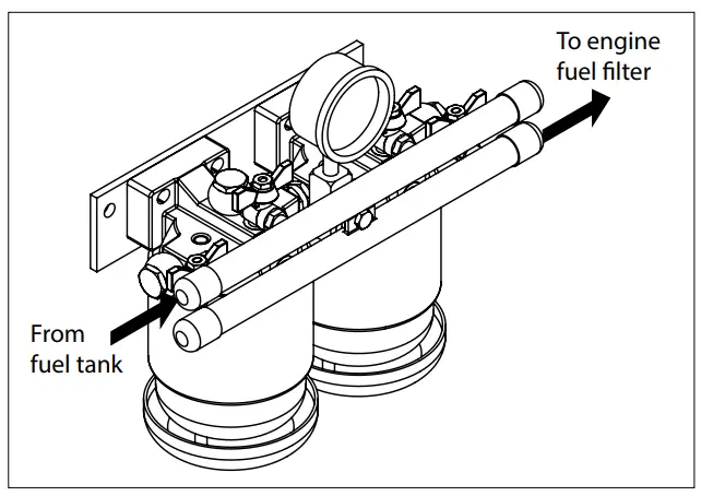
Select a suitable position in the fuel system between the fuel supply pump and the fuel tank for the additional filter The position selected must be free from vibrations, and allow for easy inspection and replacement. It is also recommended that a diesel fuel additive be used to combat algae growth, particularly in warmer climates. Additives reduce the chances of algae growth in the diesel fuel in warmer clime.
![]() IMPORTANT See the certification data on the filter i.e CE,ABYC or Solas
IMPORTANT See the certification data on the filter i.e CE,ABYC or Solas
![]() IMPORTANT For fuel hose use A1 quality tube for petrol and diesel with NBR inside.
IMPORTANT For fuel hose use A1 quality tube for petrol and diesel with NBR inside.
Raw water circuit
The engine heat exchange circuit is represented in the block diagram below:

The sequence is as follows:
- the raw water cools the internal coolant circuit is cooled;
- then the raw water passes a hose connection to the injection point
- Then the exhaust elbow is cooled
- the the raw water is injected into the exhaust gasses and mixed with the exhaust gasses it goes overboard.
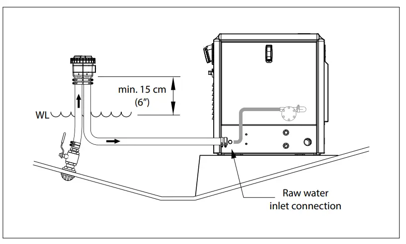
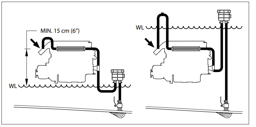
![]() IMPORTANT If the injection point at the exhaust bend of the engine is situated at a height less than 15 cm (6”) above the waterline an air vent must be installed; see ‘Exhaust system’.
IMPORTANT If the injection point at the exhaust bend of the engine is situated at a height less than 15 cm (6”) above the waterline an air vent must be installed; see ‘Exhaust system’.
Installation material
The parts needed to connect the raw water supply to the generator set are included in the scope of delivery.
These parts are:
- Sea water strainer FTR330,
- Water scoop,
- Ball valve,
- Hose pillar,
- Hose clamps and
- 2 metre hose
For inner diameter:
| Generator set model | Diameter | |
| GHX 8, GHX 9, GHX 14, GHX 17, GHX 24,GLX 6, GLX 7, GLX 14, GLX 17 | 19 mm | ( 3/4 in. ) |
| GLX 20, GLX 24 | 25 mm | ( 1 in. ) |
Raw water inlet
When choosing a position for the water inlet, take the following into account:
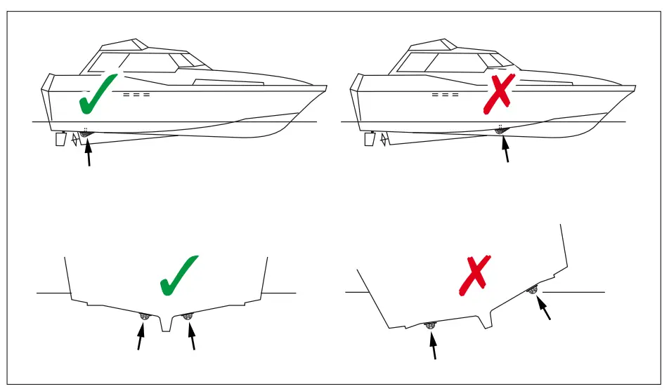
- The water inlet must be in a place where a continuous supply of water is available under all circumstances. Close to the bow, where turbulence can occur at higher speeds, is a less suitable place. This applies is particular to high speed power boats! The inlet must also remain under water when the vessel rolls. If air is sucked in instead of water, insufficient cooling as well as damage to the water pump impeller is a consequence of dry running.

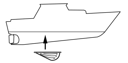
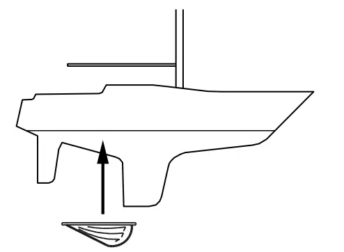
- Place the water scoop with the opening facing forwards or backwards depending on the type of boat:
 NOTE The recommendation below is based on the assumption that the generator set will be used during cruising.IMPORTANT Always close the sea cock of the generator raw water supply if the generator set is NOT running during cruising. Especially when the scoop is fitted with the opening facing forward, this to prevent water being forced in.
motor boats which have a maximum speed of less than 10 knots
sailing boatsthe water scoop can be best fitted with the opening facing backwards
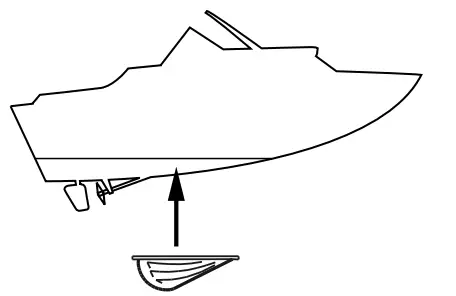
motor boats which can reach a speed of 10 knots or more
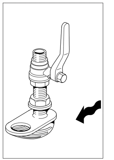
the water scoop must be fitted with the opening facing forward - The skin fitting with the sea cock must provide minimum restriction to water flow. The ball valve is equipped with a lever type handle that operates in a 90 degree arc. This design gives a clear indication of whether the valve is open or shut. Industry standards/ requirements typically require that the sea cock be rigidly attached to the hull at the water pickup.
Sea cock location should be readily accessible for quick, easy operation.
NOTE
![]() A through-hull fitting that is completely flush with the surface of the boat’s hull and without an external strainer may be necessary for the engine raw water intake on very high-speed boats. The protrusion of a standard type through hull fitting and a strainer can cause a Venturi effect on the intake of a high speed boat, creating a suction which works against the raw water pump causing an inadequate supply of cooling water to the engine.
A through-hull fitting that is completely flush with the surface of the boat’s hull and without an external strainer may be necessary for the engine raw water intake on very high-speed boats. The protrusion of a standard type through hull fitting and a strainer can cause a Venturi effect on the intake of a high speed boat, creating a suction which works against the raw water pump causing an inadequate supply of cooling water to the engine.
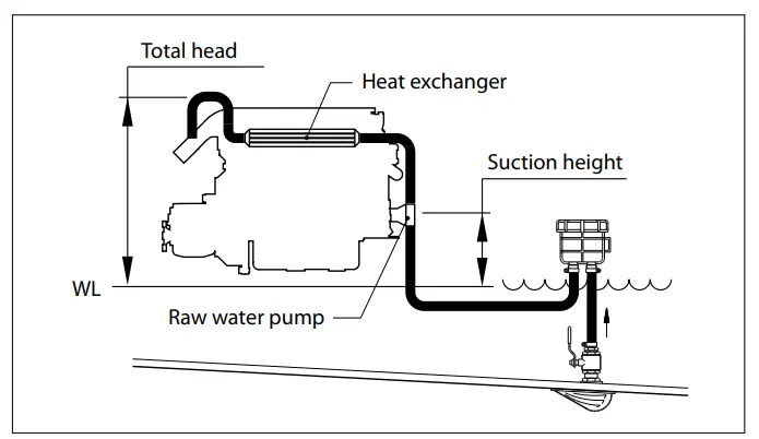
The capacity of the raw water pump is related to suction height and the total head. The higher the suction height or the total head the lesser the capacity of the pump will be.
Never exceed the maximum values, as per table, for the suction height and the total head.
| Generator set model | Raw water pump capacity at max engine rpm | Total head at max. capacity | Raw water inlet connection | ||
| l/min | Imp (UK) gal/ min | US gal/min | |||
| GHX 8, GHX 9, GHX 14, GHX 17, GHX 24, GLX 6, GLX 7, GLX 14, GLX 17 | 20 | 4.4 | 5.3 | 2 m (6’ 7”) water | 20 mm |
| GLX 20, GLX 24 | 60 | 13.2 | 15.9 | 2 m (6’ 7”) water | 25 mm |
![]() IMPORTANT Use a sealant when mounting this skin fitting with the scoop.
IMPORTANT Use a sealant when mounting this skin fitting with the scoop.
Raw water inlet hose
Raw water inlet hose supplied is a wire reinforced hose of adequate wall thickness to prevent it from collapsing from pump suction. Be sure to secure hose connections with hose clamps. Secure hose to prevent contact with any moving parts of the engine.
![]() IMPORTANT The suction hose is to be kept as short as possible. Raw water plumbing should exclude bends as much as possible.
IMPORTANT The suction hose is to be kept as short as possible. Raw water plumbing should exclude bends as much as possible.
Seawater strainer
Install raw water strainer in an area where it will be easily accessible for inspection and cleaning. Strainer should be installed in water inlet hose after the sea cock (water inlet valve) to allow operator to shut off water when cleaning strainer.
Fittings
![]() IMPORTANT
IMPORTANT
If other/more fittings or pipes then included in the scope of supply are needed use only bronze hardware. If more lenght of hose is needed then included in the scope of supply use only MARINEWATER HOSE, steel reinforced and suitable for 2.5 bar (35 psi) both suction or pressure.
Use sealing compound or tape at all connections to prevent air leaks. The neoprene impeller in the raw water pump should never be run dry. All hose joints should be double clamped with 304/316 stainless-steel hose clamps. T-bolt clamps are even better but must be 304/316 stainless.
Exhaust system
Wet exhaust systems
The exhaust system of VETUS generator sets is water injected. The cooling water that has passed the heat exchanger is mixed with the exhaust gases. Temperature and volume of the gases are thereby reduced considerably so that a rubber exhaust hose can be used.
Beyond conveying exhaust gases and cooling system sea water out of the boat, the other purpose of the exhaust system is to prevent sea water intrusion into the engine (at the exhaust outlet) under all conceivable conditions of boat trim, boat operation, sea conditions, and heel angle while not exceeding the manufacturer’s back pressure recommendations. Seawater intrusion is usually catastrophic to the engine.
![]() IMPORTANT
IMPORTANT
The engine supplier is not in a position to judge what installation characteristics will prevent water intrusion in all conceivable circumstances. That judgment is the responsibility of the engine installer. What we as the manufacturer can do is advise the best practice
Installation material
The parts needed to connect the exhaust system are included in the scope of delivery.
These parts are:
- Waterlock,
- Muffler,
- Gooseneck,
- Transom connection and
- 3 metre Exhaust hose.
For inner diameter:
| Generator set model | Diameter |
| GHX 8, GHX 9, GHX 14, GHX 17, GLX 6, GLX 7 | 40 mm |
| GHX 24, GLX 14, GLX 17 | 50 mm |
| GLX 20, GLX 24 | 60 mm |
Waterline
We need to define the water line for exhaust installation purposes. By water line we mean the highest point the water level can reach, at the location of the exhaust through hull fitting, from all conceivable causes – other than passing waves of a duration of not more than a second or two. This worst case water level could be caused by any of the following: backing down aggressively, turning aggressively, coming up onto a plane, decelerating off a plane, extreme boat trim, high seas, wallowing in following seas, heeling, etc. Here after these instructions will refer exclusively to this worst case water level as the relevant water level to plan a good installation.
Prevention of siphoning
Another means of water intrusion is through the raw water intake sea-cock. This can occur when the raw water injection point at the exhaust elbow is below the worst case water level.
What happens is that, upon engine shut-down, raw water siphons from the intake sea-cock, up through the raw water cooling circuit containing the raw water pump, heat exchanger, and water injected exhaust elbow, into the water lift muffler.
This raw water will siphon past the impeller of the sea water pump and fill the muffler and all hoses attached to the muffler until the outside water level is reached. If the engine exhaust manifold is below the worst-case water level, raw water will simply pour into the cylinders, destroying the engine.
This form of water intrusion is avoided by the proper installation of an air vent (anti-siphon) in the raw water circuit between the heat exchanger outlet and the water injected exhaust elbow inlet. The air vent must be well above the worst case water level under all conceivable conditions of boat trim, boat operation, sea conditions, and heel angle. The anti-siphon break and the exhaust hose point should be located as near to the boats centre-line as possible; especially on sail-boats due to large and steady healing. The anti-siphon must be accessible for maintenance.
The valve of an air vent is closed during normal operation of the engine; during a standstill of the engine the water pressure in the raw water line drops and the valve will open to let air in to break the water column.
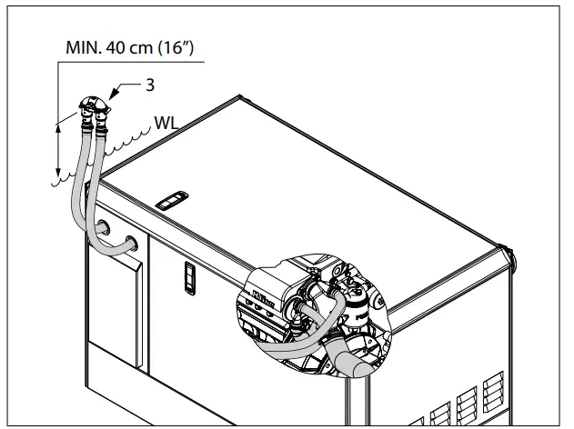
Air vent installation
Remove the connection hose (1) from the heat exchanger to raw water inlet at the exhaust elbow.
Remove the blind plugs (2) out of the wall of the sound box.
Feed the hoses through the released holes. Fit the air vent (3) at a height of minimal 40 cm (16”) but not more than 2 metres (3’ 8”) above the water line. In a sail-boat the air vent must also be positioned as far as possible midships. This prevents the air vent from being less than the required 40 cm (16”) above the waterline when the ship is sailing is heeling. These hoses must be installed in a sloped position.
If an air vent without a valve is installed a vent hose of 8 mm diam. (5/8”) must be installed. When the engine is running a small amount of water will escape, but as soon as the engine stops air will enter the water hose and break the siphoning ability of the system thus preventing the water from penetrating the exhaust.
Dimensional recommendations
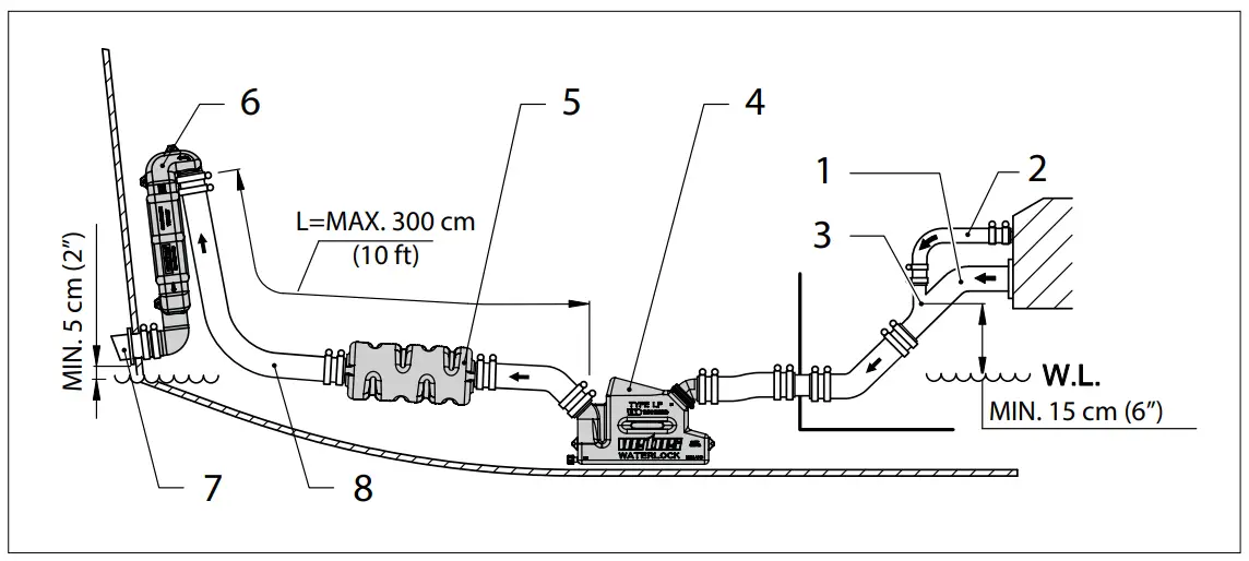
System with water injection point 15 cm (6 in.) or more above the waterline
System with water injection point below or less than 15 cm (6 in.) above the waterline
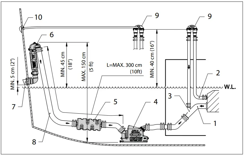
- Exhaust manifold
- Cooling water
- Water injection point
- Waterlock, WLOCKL40R / WLOCKL50R / WLOCKLP60
- Muffler, DEMPMP40 / DEMPMP50 / DEMPMP60
- Goose neck, WLOCKLT40 / WLOCKLT50 / WLOCKL60
- Transom fitting, TRC40R / TRC50R / TRC60R
- Exhaust hose
- Air vent
- Through hull fitting
Waterlock capacity
![]() NOTE The waterlock is sized to hold multiples of the volume of water that spills back from the exhaust highest point when the engine shuts off.
NOTE The waterlock is sized to hold multiples of the volume of water that spills back from the exhaust highest point when the engine shuts off.
![]() IMPORTANT Prolonged cranking of the starter may cause excessive sea water to build up between the engine and the high point.
IMPORTANT Prolonged cranking of the starter may cause excessive sea water to build up between the engine and the high point.
Each time cranking is interrupted additional water may spill back into the muffler. In time this cumulative spill back can flood the engine. Unusual cranking and/or cranking interruptions must be monitored and the muffler drained before excessive water build-up occurs. This may be made more convenient by installing a suitable, non-corrosive valve at the muffler drain fitting.
Electrical installation
Electrical system engine (12 volt)
![]() IMPORTANT The electrical system is carried out in 12 Volt with negative ground.
IMPORTANT The electrical system is carried out in 12 Volt with negative ground.
The electrical wiring has already been fitted to generator set and the built-in control panel.
The battery cables (as supplied) have a standard length of 2.5 metre (8’ 4”); if longer cables are needed a larger cross-section may be required. The permissible voltage drop on both the positive and negative lead between starter motor and battery must not exceed 8 %.
The battery cables are already connected inside the generator set housing.
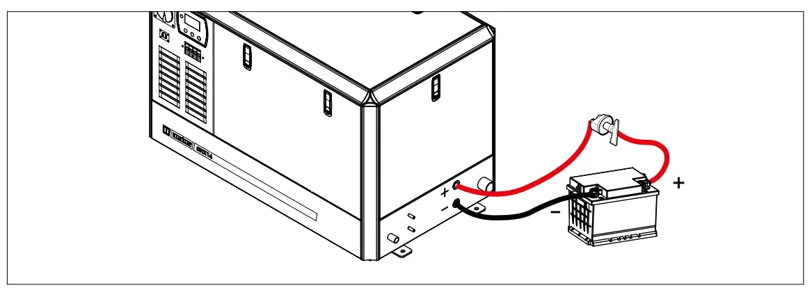
The positive battery cable (RED) to the positive (+) terminal of the starter motor relay and the negative battery cable (BLACK) to the engine motor block.
Connect the battery cables to the battery terminals. Install a battery main switch in the positive cable.
Never use the hull, in case of a steel vessel, as earth return!
Connection of the negative terminal(s) of the battery(ies) to the steel ship’s hull, for earthing purposes, is permissible at one point only.
![]() NOTE The wiring system for the engine and the domestic supply must be kept completely separate and must be individually connected to the batteries.
NOTE The wiring system for the engine and the domestic supply must be kept completely separate and must be individually connected to the batteries.
![]() IMPORTANT Disconnect the battery cables if electrical welding has to be done. Otherwise, the welding can damage the diodes of the alternator.
IMPORTANT Disconnect the battery cables if electrical welding has to be done. Otherwise, the welding can damage the diodes of the alternator.
Remote control panel
If required a remote control panel can be connected to the generator set. Remote control panel complete with 8 meter (26 ft 3 in) connection cable, Vetus art.code: MPRGEN.
Electrical system generator
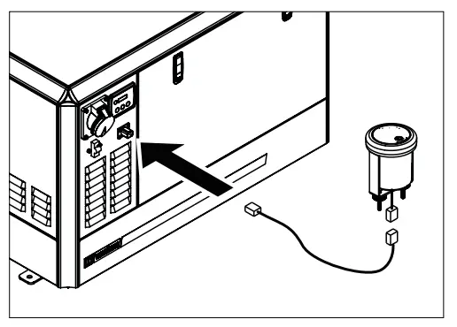
The generator, automatic voltage regulator and circuit breaker are completely pre wired. The generator set is equipped with a CEEform socket to hook up the ship’s power supply system to the generator with the supplied plug.
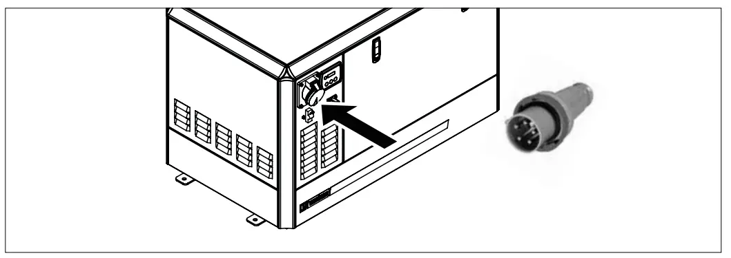
Depending on the generator output voltage the plug can be:
- P+N+E (unbalanced single phase with neutral),
- 2P+E (balanced single phase),
- 3P+E (3 phase without neutral), or
- 3P+N+E (three phase with neutral).
Current rating of the plug and socket is accommodated to the maximum output current of the generator.
Use a cable with wires with sufficient cross-section for the maximum current:
Based on commonly available cable with wires with an insulation temperature rating of 85-90°C use minimum cross-sections as per table below.
Note a de-rating of 0.82 for an engine room temperature of 60°C and a de-rating of 0.7 for a cable with 4 to 6 wires has been applied.
| Cross section in mm2 | Maximum current in Amps at number of current carrying conductors | AWG cross-section | Maximum current in Amps at number of current carrying conductors | |||
| 2 or 3 | 4 | 2 or 3 | 4 | |||
| 2,5 | 25 | 17 | 12 | 33 | 23 | |
| 4 | 33 | 23 | 10 | 45 | 32 | |
| 6 | 41 | 29 | 8 | 57 | 40 | |
| 10 | 57 | 40 | 6 | 82 | 57 | |
| 16 | 82 | 57 | 4 | 111 | 77 | |
| 25 | 115 | 80 | 2 | 148 | 103 | |
| 35 | 152 | 106 | 1 | 172 | 121 | |
| 50 | 189 | 132 | 0 | 201 | 141 | |
| 70 | 234 | 164 | 00 | 234 | 164 | |
Technical data
| Model | GHX 8 SIC | C GHX 14 SIC | GHX 24 SIC | GLX 6 SIC | GLX 14 SIC | GHX 8 TIC | GHX 14 TIC | GHX 24 TIC | ||
| Power | 8kW | 14kW | 24kW | 6kW | 14kW | 8kVA | 14kVA | 24kVA | ||
| at Power Factor (coscp) | 1,0 | 1,0 | 1,0 | 1,0 | 1,0 | 0,8 | 0,8 | 0,8 | ||
| Voltage | 230V | 230V | 230V | 230V | 230V | 3 x400V | 3 X 400V | 3x400V | ||
| Current | 34A | 60A | 104A | 28A | 61 A | 9A | 20A | 35A | ||
| Voltage | (115 V) | (115V) | (3X 230V) | (3 X 230V) | (3 X 230V) | |||||
| Current | (56 A) | (122 A) | (16A) | (35 A) | (60 A) | |||||
| Frequency | 50Hz | 50Hz | 50Hz | 50Hz | 50Hz | 50Hz | 50Hz | 50 Hz | ||
| Overload power | Maximum start current for electro-motor 1.5x nominal generator current | |||||||||
| Short circuit current | >300% | |||||||||
| Power Factor (coscφ) | Between 0.8 inductive and 1 | |||||||||
| Operating range | Minimal 4 % of nominal rpm | |||||||||
| Protection grade | IP 44 | |||||||||
| Max. temperature taw water | 30°C (86°F) | |||||||||
| Max. ambient temperature | 40°C (104°F) | |||||||||
| Max. inclination angle longitudinal | 15° | |||||||||
| Max. angle of inclination angle athwartships | 25° | |||||||||
| Weight | 185 kg | 295 kg | 436 kg | 245 kg | 395 kg | 185 kg | 275 kg | 395 kg | ||
| Model | GLX 14 TIC | C GLX 20 TIC | C GHX 9 SIC | GHX 17 SIC | GLX 7 SIC | GLX 17 SIC | GHX 17 TIC | GLX 17 TIC | GLX 24 TIC | ||
| Power | 14kVA | 20kVA | 9kW | 17kW | 7kW | 17kW | 17 kVA | 17 kVA | 24kVA | ||
| at Power Factor (cos φ) | 0,8 | 0,8 | 1,0 | 1,0 | 1,0 | 1,0 | 0,8 | 0,8 | 0,8 | ||
| Voltage | 3x400V | 3x400V | 240V | 240V | 120V | 120V | 3 x240V | 3x 240V | 3 x240V | ||
| Current | 20A | 29A | 37 A | 71 A | 62A | 142 A | 41A | 41A | 57 A | ||
| Voltage | (3 X230V) | (3 x230V) | (240V) | (240V) | (3x415V) | (3 x415V) | (3 x415 V) | ||||
| Current | (35 A) | (SO A) | (31A) | (71 A) | (24A) | (24A) | (33 A) | ||||
| Frequency | 50Hz | SOHz | 60Hz | 60Hz | 60Hz | 60Hz | -60Hz | 60 Hz | 60Hz | ||
| Overload power | Maximum start current for electro-motor 1.5x nominal generator current | ||||||||||
| Short circuit current | >300% | ||||||||||
| Power Factor (cos cp) | Between 0.8 inductive and1 | ||||||||||
| Operating range | Minimal 4% of nominal rpm | ||||||||||
| Protection grade | IP44 | ||||||||||
| Max. temperature raw water | 30°C (86°F) | ||||||||||
| Max. ambient temperature | 40°C (104°F) | ||||||||||
| Max. inclination angle longitudinal | 15° | ||||||||||
| Max. angle of inclination angle athwartships | 25° | ||||||||||
| Weight | 375 kg | 505 kg | 185 kg | 295 kg | 245 kg | 395 kg | 295 kg | 395 kg | 505 kg | ||
Overall dimensions
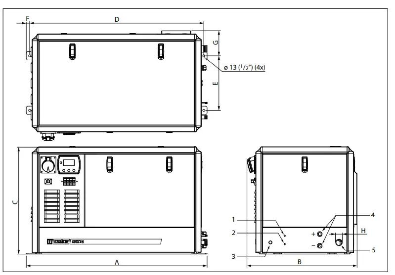
| A | B | C | D | E | F | G H |
| GLX 6 SIC GLX 7 SIC 927 | 657 | 644 | 887 | 297 | 20 | 165 40 |
| (36 1/2”) | (25 7/8”) | (25 3/8”) | (34 15/16”) | (11 11/16”) | (13/16”) | (6 1/2”) |
| GHX 8 SIC / TIC GHX 9 SIC 884 | 659 | 571 | 844 | 327 | 20 | 150 40 |
| (34 13/16”) | (25 15/16”) | (22 1/2”) | (33 1/4”) | (12 7/8”) | (13/16”) | (5 7/8”) |
| GHX 14 SIC / TIC GHX 17 SIC / TIC 1082 | 659 | 641 | 1042 | 327 | 20 | 150 40 |
| (42 5/8”) | (25 15/16”) | (25 1/4”) | (41”) | (12 7/8”) | (13/16”) | (5 7/8”) |
| GLX 14 SIC / TIC GLX 17 SIC / TIC 1172 | 659 | 644 | 1132 | 327 | 20 | 150 50 |
| (46 1/8”) | (25 15/16”) | (25 3/8”) | (44 9/16”) | (12 7/8”) | (13/16”) | (5 7/8”) |
- Fuel supply ø 8 mm
- Fuel return ø 8 mm
- Raw water inlet ø 19 mm
- Battery connections
- Exhaust ø ‘H’
Customer Support
Fokkerstraat 571 – 3125 BD Schiedam – Holland
Tel.: +31 (0)88 4884700 – [email protected] – www.vetus.com