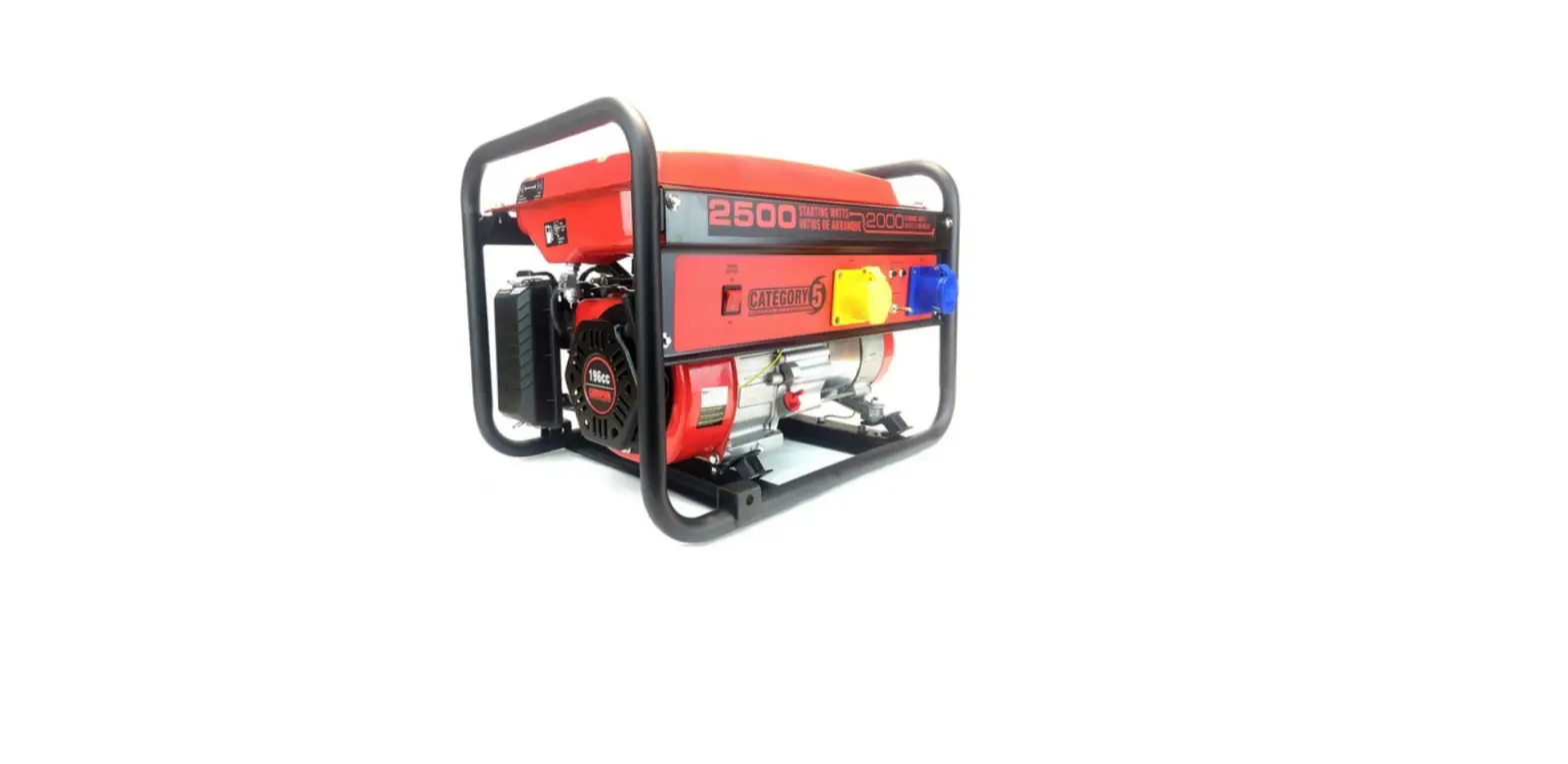
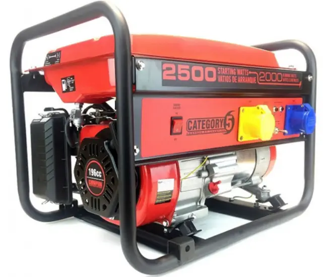
CHAMPION CPG2500 Portable Generator
SAVE THESE INSTRUCTIONS
Important Safety Instructions are included in this manual.
INTRODUCTION
- Congratulations on purchasing your generator.
- Please follow these instructions and maintain it correctly.
Portable Power Generator
- This unit is a petrol engine driven AC generator used for supply electrical power.
Accessories
- CPE manufactures and supplies a series of accessories. See local dealer for more information.
This Booklet
- We reserve the right to change, alter or improve the product and this manual without prior notice.
- Record the model and serial numbers as well as date and place of purchase for future reference. Have this information available when ordering parts and when making technical or warranty inquiries.
MANUAL CONVENTIONS
- Please familiarize yourself with the following symbols. The safety symbol and key words are safety warnings. Follow all safety messages to avoid accidents or injury.
- DANGER indicates an imminently hazardous situation which, if not avoided, will result in death or serious injury.
- WARNING indicates a potentially hazardous situation which, if not avoided, could result in death or serious injury.
- CAUTION indicates a potentially hazardous situation which, if not avoided, may result in minor or moderate injury.
- CAUTION Using without the safety alert symbol indicates a potentially hazardous situation which, if not avoided, may result in property damage.
NOTE
- If you have questions regarding your generator, we can help. Please contact yor local dealer.
SAFETY RULES
WARNING
- Read this manual thoroughly before operating your generator. Failure to follow instructions could result in serious injury or death.
- The engine exhaust from this product contains chemicals that are known to cause serious health problems and even death.
DANGER
- Generator exhaust contains carbon monoxide, a colorless, odorless, poison gas. Breathing carbon monoxide will cause nausea, dizziness, fainting or death. If you start to feel dizzy or weak, get to fresh air immediately.
- Operate generator outdoors only in a well ventilated area.
- DO NOT operate the generator inside any building, including garages, basements, crawlspaces and sheds, enclosure or compartment, including the generator compartment of a recreational vehicle. DO NOT allow exhaust fumes to enter a confi ned area through windows, doors, vents or other openings.
- DANGER CARBON MONOXIDE: using a generator indoors CAN KILL YOU IN MINUTES.
DANGER
- Rotating parts can entangle hands, feet, hair, clothing and/or accessories.
- Traumatic amputation or severe laceration can result.
- Keep hands and feet away from rotating parts. Tie up long hair and remove jewelry.
- Operate equipment with guards in place.
- DO NOT wear loose-fi tting clothing, dangling drawstrings or items that could become caught.
Generator produces powerful voltage.
- DO NOT touch bare wires or receptacles.
- DO NOT use electrical cords that are worn, damaged or frayed.
- DO NOT operate generator in wet weather.
- DO NOT allow children or unqualifi ed persons to operate or service the generator
- Use a ground fault circuit interrupter (GFCI) in damp areas and areas containing conductive material such as metal decking.
- Use approved transfer equipment to isolate generator from your electric utility and Notify your utility company before connecting your generator to your power system.
WARNING
- Sparks can result in fi re or electrical shock.
When servicing the generator:
- Disconnect the spark plug wire and place it where it cannot contact the plug.
- Running engines produce heat. Severe burns can occur on contact.
- Combustible material can catch fi re on contact.
- DO NOT touch hot surfaces.
- Avoid contact with hot exhaust gases.
- Allow equipment to cool before touching. Maintain at least 3 ft. (91.4 cm) of clearance on all sides to ensure adequate cooling.
- Maintain at least 5 ft. (1.5 m) of clearance from combustible materials.
Medical and Life Support Uses.
- In an emergency, call emergency services immediately. NEVER use this product to power life support devices or life support appliances.
- NEVER use this product to power medical devices or medical appliances.
- Inform your electricity provider immediately if you or anyone in your household depends on electrical equipment to live.
- Inform your electrical provider immediately if a loss of power would cause you or anyone in your household to experience a medical emergency.
DANGER
- Fuel and fuel vapors are highly fl ammable and extremely explosive.
- Fire or explosion can cause severe burns or death. Unintentional startup can result in entanglement, traumatic amputation or laceration.
When adding or removing fuel:
- Turn the generator off and let it cool for at least two minutes before removing the fuel cap. Loosen the cap slowly to relieve pressure in the tank.
- Only fi ll or drain fuel outdoors in a well-ventilated area. DO NOT pump gas directly into the generator at the gas station. Use an approved container to transfer the fuel to the generator.
- DO NOT overfi ll the fuel tank.
- Always keep fuel away from sparks, open fl ames, pilot lights, heat and other sources of ignition.
- DO NOT light or smoke cigarettes.
When starting the generator:
- DO NOT attempt to start a damaged generator. Make certain that the gas cap, air fi lter, spark plug, fuel lines and exhaust system are properly in place. Allow spilled fuel to evaporate fully before attempting to start the engine.
- Make certain that the generator is resting fi rmly on level ground.
- When operating the generator:
- DO NOT move or tip the generator during operation. DO NOT tip the generator or allow fuel or oil to spill.
When transporting or servicing the generator:
- Make certain that the fuel shutoff valve is in the off position and the fuel tank is empty.
- Disconnect the spark plug wire.
- When storing the generator:
- Store away from sparks, open fl ames, pilot lights, heat and other sources of ignition.
- Operation of this equipment may create sparks that can start fi res around dry vegetation.
- A spark arrestor may be required. The operator should contact local fi re agencies for laws or regulations relating to fi re prevention requirements.
WARNING
- Rapid retraction of the starter cord will pull hand and arm towards the engine faster than you can let go. Unintentional startup can result in serious injury. Broken bones, fractures, bruises or sprains could result.
- When starting engine, pull the starter cord slowly until resistance is felt and then pull rapidly to avoid kickback.
- DO NOT start or stop the engine with electrical devices plugged in.
CAUTION
- Exceeding the generator’s running capacity can damage the generator and/or electrical devices connected to it.
- DO NOT overload the generator.
- Start the generator and allow the engine to stabilize before connecting electrical loads.
- Connect electrical equipment in the off position, and then turn them on for operation.
- Turn electrical equipment off before stopping the generator.
- DO NOT tamper with the governed speed.
- DO NOT modify the generator in any way.
Improper treatment or use of the generator can damage it, shorten its life and void your warranty.
- Use the generator only for intended uses.
- Operate only on level surfaces.
- DO NOT expose generator to excessive moisture, dust, or dirt.
- DO NOT allow any material to block the cooling slots.
- If connected devices overheat, turn them off and disconnect them from the generator.
DO NOT use the generator if:
- Electrical output is lost
- Equipment sparks, smokes or emits fl ames
- Equipment vibrates excessively
ASSEMBLY
- Your generator requires some assembly. This unit ships from our factory without oil. It must be properly serviced with fuel and oil before operation.
- If you have any questions regarding the assembly of your generator, contact yor local dealer. Please have your serial number and model number available.
Remove the Generator from the Shipping Carton
- Set the shipping carton on a solid, fl at surface.
- Remove everything from the carton except the generator.
- Carefully cut each corner of the box from top to bottom. Fold each side fl at on the ground to provide a surface area to install the wheel kit and support leg.
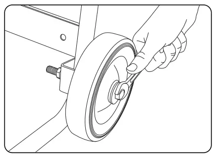
Install the Wheel Kit (Optional Extra)
CAUTION
The wheel kit is not intended for over-the-road use.
You will need the following tools to install the wheels:
- 17 mm wrench OR adjustable wrench (not included)
- Socket wrench with a 16 mm socket (not included)
- Pliers (not included)
- Before adding fuel and oil, tip the generator on it’s side.
- Slide the M10x120 fl ange bolt through the washer, sleeve and wheel.
- Slide the bolt through the mount point on the frame.
- Fasten securely with the M10 lock nut.
- Repeat steps 2-4 to attach the second wheel.

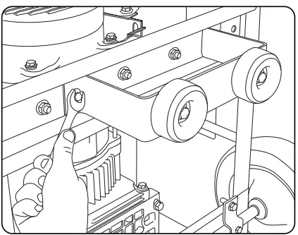
Install the Support Leg
- Attach the vibration mounts to the support leg with a fl ange bolt M8 x 25 and fl ange lock nuts.
- Attach the support leg to the generator frame with fl ange bolts M8 x 16 and fl ange lock nuts and fasten securely. DO NOT over tighten the lock nuts.
- Tip the generator slowly so that it rests on the wheels and support leg.

Connect the Battery (Electric Start Models only)
- Remove the protective cover from the red (+) lead on the battery.
- Attach the red (+) lead to the red (+) terminal on the battery with the cap screw (M5x10) and secure with the lock washer (M5).
- Repeat steps 1-2 for the black (–) battery lead.
Add Engine Oil
CAUTION
- DO NOT attempt to crank or start the engine before it has been properly fi lled with the recommended type and amount of oil.
- Damage to the generator as a result of failure to follow these instructions will void your warranty.
NOTE
The recommended oil type is 10W-30 automotive oil.
- Place the generator on a fl at, level surface.
- Remove oil fi ll cap/dipstick to add oil.
- Add oil and replace oil fi ll cap/dipstick. DO NOT OVERFILL.
- Check engine oil level daily and add as needed.

NOTE
- Once oil has been added, a visual check should show oil about 1-2 threads from running out of the fi ll hole. If using the dipstick to check oil level, DO NOT screw in the dipstick while checking.
CAUTION
- The engine is equipped with a low oil shut-off and will stop when the oil level in the crankcase falls below the threshold level.
NOTE
- Check oil often during the break-in period. Refer to the Maintenance section for recommended service intervals.
- The generator rotor has a sealed, pre-lubricated ball bearing that requires no additional lubrication for the life of the bearing.
- We consider the fi first 5 hours of run time to be the break-in period for the unit.
- During the break-in period stay at or below 50% of the running watt rating and vary the load occasionally to allow stator windings to heat and cool. Adjusting the load will also cause engine speed to vary and help seat piston rings. After the 5-hour break-in period, change the oil.

- Weather will affect engine oil and engine performance. Change the type of engine oil used based on weather conditions to suit the engine needs.
- Synthetic oil may be used after the 5 hour initial break-in period. Using synthetic oil does not increase the recommended oil change interval. Full synthetic 5W-30 oil will aid in starting in cold ambient <5ºC (41ºF)

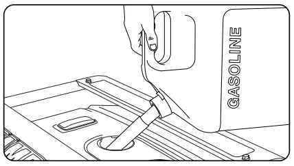
Add Fuel
- Use clean, fresh, regular unleaded fuel with a minimum octane rating of 85 and an ethanol content of less than 10% by volume.
- DO NOT mix oil with fuel.
- Clean the area around the fuel cap.
- Remove the fuel cap.
- Slowly add fuel to the tank. DO NOT OVERFILL. Fuel can expand after fi lling. A minimum of ¼ in. (6.4 mm) of space left in the tank is required for fuel expansion, more than ¼ in. (6.4 mm) is recommended. Fuel can be forced out of the tank as a result of expansion if it is overfi lled, and can affect the stable running condition of the product. When fi lling the tank, it is recommended to leave enough space for the fuel to expand.

- Screw on the fuel cap and wipe away any spilled fuel.
CAUTION
- Use regular unleaded gasoline with a minimum octane rating of 85.
- Do not mix oil and gasoline.
- Fill tank to approximately ¼ in. (6.4 mm) below the top of the tank to allow for fuel expansion.
- DO NOT pump gas directly into the generator at the gas station. Use an approved container to transfer the fuel to the generator.
- DO NOT fi ll fuel tank indoors.
- DO NOT fi ll fuel tank when the engine is running or hot.
- DO NOT overfi ll the fuel tank.
- DO NOT light cigarettes or smoke when fi lling the fuel tank.
WARNING
Pouring fuel too fast through the fuel screen may result in blow back of fuel at the operator while fi lling.
NOTE
- Our engines work well with 10% or less ethanol blend fuels.
When using blended fuels there are some issues worth noting:
- Ethanol-gasoline blends can absorb more water than gasoline alone.
- These blends can eventually separate, leaving water or a watery goo in the tank, fuel valve and carburetor.
- With gravity-fed fuel supplies, this compromised fuel can be drawn into the carburetor and cause damage to the engine and/or potential hazards.
- There are only a few suppliers of fuel stabilizer that are formulated to work with ethanol blend fuels.
- Any damages or hazards caused by using improper fuel, improperly stored fuel, and/ or improperly formulated stabilizers, are not covered by manufacture’s warranty.
- It is advisable to always shut off the fuel supply, run the engine to fuel starvation and drain the tank when the equipment is not in use for more than 30 days.
Grounding
- Your generator must be properly connected to an appropriate ground to help prevent electric shock.
WARNING
- Failure to properly ground the generator can result in electric shock.
- A ground terminal connected to the frame of the generator has been provided on the power panel. For remote grounding, connect of a length of heavy gauge
(12 AWG minimum) copper wire between the generator ground terminal and a copper rod driven into the ground. We strongly recommend that you consult with a qualifi ed electrician to ensure compliance with local electrical codes.
OPERATION
Generator Location
- Never operate the generator inside any building! (See safety warnings section).
- In some areas generators must be registered with the local utility company. Generators used on construction sites may be subject to local rules and regulations.
- Keep on a fl at, level surface. Generators must have at least 5 ft (1.5m) clearance from all combustible material.
- In addition they must have at least 3 ft (91.4cm) of clearance on all sides to allow for adequate cooling, maintenance and servicing.
- Generators should never be started or operated in ant location that will not allow for adequate cooling of
the generator and/or the muffl er. Allow generators to cool before storage or transportation. - Do not place the generator near any vents or intakes.
- Carefully consider wind and air currents when placing generator.
- Failure to follow proper safety precautions may void manufacturer’s warranty.
WARNING
- Do not operate or store the generator in rain, snow, or wet weather.
- Using a generator or electrical appliance in wet conditions, such as rain or snow, or near a pool or sprinkler system, or when your hands are wet, could result in electrocution.
- During operation the muffl er and exhaust fumes produced will become hot. If adequate cooling and breathing space are not supplied, or if the generator is blocked or contained, temperatures can become extremely heated and may lead to fi re.
Grounding
- The generator system ground connects the frame to the ground terminals on the power panel. The system ground is connected to the AC neutral wire.
Surge Protection
CAUTION
- Voltage fl uctuation may impair the proper functioning of sensitive electronic equipment.
- Electronic devices, including computers and many programmable appliances use components that are designed to operate within a narrow voltage range and may be affected by momentary voltage fl uctuations. While there is no way to prevent voltage fl uctuations, you can take steps to protect sensitive electronic equipment.
- Install UL1449, CSA-listed, plug-in surge suppressors on the outlets feeding your sensitive equipment. Surge suppressors come in single- or multi-outlet styles. They’re designed to protect against virtually all short-duration voltage fl uctuations.
Starting the Engine
- Make certain the generator is on a fl at, level surface.
- Disconnect all electrical loads from the generator. Never start or stop the generator with electrical devices plugged in or turned on.
- Turn the Fuel Valve to the “ON” position.
- Move the choke lever to the “CHOKE” position.
- Flip the ignition switch to the “ON” position.
- For models that have an ELECTRIC START: Press and hold the ignition switch to the “START” position. Release as the engine begins to roll over. If the engine fails to start within fi ve seconds, release the switch and wait at least ten seconds before attempting to start the engine again.
- RECOIL START: Pull the starter cord slowly until resistance is felt and then pull rapidly
- Do not over-choke. As as soon as engine starts, move the choke lever to the “RUN” position.
NOTE
- Keep choke lever in “Choke” position for only 1 pull of the recoil starter. After fi rst pull, move choke lever to the “Run” position for up to the next 3 pulls of the recoil starter. Too much choke will cause the engine not to start.
- If the engine starts but does not run make certain that the generator is on a fl at, level surface. The engine is equipped with a low oil sensor that will prevent the engine from running when the oil level falls below a critical threshold.
- When the battery switch is in the “ON” position, the switch will light up if the battery is sending out a charge. If the switch does not light up while in the “ON” position, check that the battery connection is still good.
- The supplied 12V 15AH battery does re-charge while the engine is running, but it is also recommended that the battery be fully charged at least once per month.
Connecting Electrical Loads
- Let the engine stabilize and warm up for a few minutes after starting
- Plug in and turn on the desired 120/240 Volt AC single phase, 50 Hz electrical loads.
- DO NOT connect 3-phase loads to the generator.
- DO NOT connect 60 Hz loads to the generator.
- DO NOT overload the generator.
NOTE
- Connecting a generator to your electric utility company’s power lines or to another power source may be against the law. In addition this action, if done incorrectly, could damage your generator and appliances and could cause serious injury or even death to you or a utility worker who may be working on nearby power lines. If you plan to run a portable electric generator during an outage, please notify your electric utility company immediately and remember to plug your appliances directly into the generator. Do not plug the generator into any electric outlet in your home. Doing so could create a connection to the utility company power lines. You are responsible for ensuring that your generator’s electricity does not feed back into the electric utility power lines.
- If the generator will be connected to a building electrical system, consult your local utility company or a qualifi ed electrician. Connections must isolate generator power from utility power and must comply with all applicable laws and codes.
Stopping the Engine
- Turn off and unplug all electrical loads. Never start or stop the generator with electrical devices plugged in or turned on.
- Let the generator run at no-load for several minutes to stabilize internal temperatures of the engine and generator.
- Turn the Fuel Valve to the “OFF” position.
- Let the engine run until fuel starvation has stopped the engine. This usually takes a few minutes.
- Press the Ignition Switch to the “OFF” position.
Important: Always ensure that the Fuel Valve and the Ignition Switch are in the “OFF” position when the engine is not in use.
NOTE
If the engine will not be used for a period of two (2) weeks or longer, please see the Storage section for proper engine and fuel storage.
Do Not Overload the Generator
Capacity
Follow these simple steps to calculate the running and starting watts necessary for your purposes.
- Select the electrical devices you plan on running at the same time.
- Total the running watts of these items. This is the amount of power you need to keep your items running.
- Identify the highest starting wattage of all devices identifi ed in step 1. Add this number to the number calculated in step 2. Surge wattage is the extra burst of power needed to start some electric driven equipment. Following the steps listed under “Power Management” will guarantee that only one device will be starting at a time.
Power Management
- Use the following formula to convert voltage and amperage to watts: Volts x Amps = Watts
- To prolong the life of your generator and attached devices, follow these steps to add electrical load:
- Start the generator with no electrical load attached
- Allow the engine to run for several minutes to stabilize.
- Plug in and turn on the fi rst item. It is best to attach the item with the largest load fi rst.
- Allow the engine to stabilize.
- Plug in and turn on the next item.
- Allow the engine to stabilize.
- Repeat steps 5-6 for each additional item.
NOTE
Never exceed the specifi ed capacity when adding loads to the generator.
- Operation at High Altitude
- Be aware that engine effi ciency can reduce and exhaust emissions increase when working at high altitude. Other high altitude issues can include hard starting, increased fuel consumption and spark plug fouling. This is a natural trend and cannot be altered by engine adjustment.
- An Important Message About Temperature
- Your Champion Power Equipment product is designed and rated for continuous operation at ambient temperatures up to 40°C (104°F). When your product is needed your
- product may be operated at temperatures ranging from -l5°C (5°F) to 50°C (122°F) for short periods. If the product is exposed to temperatures outside this range during storage, it should be brought back within this range before operation. In any event, the product must always be operated outdoors, in a well-ventilated area and away from doors, windows and other vents.
MAINTENANCE AND STORAGE
The owner/operator is responsible for all periodic maintenance.
WARNING
- Never operate a damaged or defective generator.
- Tampering with the factory set governor will void your warranty.
- Improper maintenance will void your warranty.
NOTE
- Maintenance, replacement, or repair of emission control devices and systems may be performed by any non-road engine repair establishment or individual.
- Complete all scheduled maintenance in a timely manner. Correct any issue before operating the generator.
Engine Maintenance
- To prevent accidental starting, remove and ground spark plug wire before performing any service.
Oil
- Change oil when the engine is warm. Refer to the oil specifi cation to select the proper grade of oil for your operating environment.
- Remove the oil drain plug with a 15 mm socket and extension (not included).
- Allow the oil to drain completely.
- Replace the drain plug.
- Remove oil fi ll cap/dipstick to add oil.
- Add oil and replace oil fi ll cap/dipstick. DO NOT OVERFILL.
- Dispose of used oil at an approved waste management facility.
NOTE
Once oil has been added, a visual check should show oil about 1-2 threads from running out of the fi ll hole. If using the dipstick to check oil level, DO NOT screw in the dipstick while checking.
Spark Plugs
- Remove the spark plug cable from the spark plug.
- Remove the plug.
- Inspect the electrode on the plug. It must be clean and not worn to produce the spark required for ignition.
- Refer to spark plug information located in the “specifi cation” page for this model.
- Carefully thread the plug into the engine.
- Use the spark plug tool (not included) to fi rmly install the plug.
- Attach the spark plug wire to the plug.

OEM spark plug: NHSP F6RTC
- Replacement spark plug: NGK BPR6ES or equivalent Make certain the *spark plug gap is 0.7 – 0.8 mm or (0.028 – 0.031 in.).
Maintenance Valve Clearance
- Intake: 0.13 – 0.17 mm (0.005 – 0.007 in.)
- Exhaust: 0.18 – 0.22 mm (0.007 – 0.009 in.)
- Note: The tech bulletin regarding the valve adjustment procedure is on www.championpowerequipment.com
MAINTENANCE AND STORAGE
Air Filter
- Remove the snap-on cover holding the air fi lter to the assembly.
- Remove the foam element.
- Wash in liquid detergent and water. Squeeze thoroughly dry in a clean cloth.
- Saturate in clean engine oil.
- Squeeze in a clean, absorbent cloth to remove all excess oil.
- Place the fi lter in the assembly.
- Reattach the air fi lter cover and snap in place.
Spark Arrester
- Allow the engine to cool completely before servicing the spark arrester.
- Remove the screws holding the cover plate which retains the end of the spark arrester to the muffl er.
- Remove the spark arrester screen.
- Carefully remove the carbon deposits from the spark arrester screen with a wire brush.
- Replace the spark arrester if it is damaged.
- Position the spark arrester in the muffl er and attach with the three screws.
CAUTION
- Failure to clean the spark arrester will result in degraded engine performance.
NOTE
- Federal and local laws and administrative requirements indicate when and where spark arresters are required.
Cleaning
CAUTION
- DO NOT spray engine with water.
- Water can contaminate the fuel system.
- Use a damp cloth to clean exterior surfaces of the engine. Use a soft bristle brush to remove dirt and oil.
- Use an air compressor (25 PSI) to clear dirt and debris from the engine.
Adjustments
- The air-fuel mixture is not adjustable. Tampering with the governor can damage your generator and your electrical devices and will void your warranty. CPE recommends that you contact your local dealer for all other service and/or adjustment needs.
Maintenance Schedule
- Follow the service intervals indicated in the following maintenance schedule.
- Service your generator more frequently when operating in adverse conditions.
| Every 8 hours or daily | |
| Check oil level | |
| Clean around air intake and muffler | |
| First 5 Hours | |
| Change oil | |
| Every 50 hours or every season | |
| Clean air filter | |
| Change oil if operating under heavy load or in hot environments | |
| Every 100 hours or every season | |
| Change oil | |
| Clean/Adjust spark plug | |
| Check/Adjust valve clearance* | |
| Clean spark arrester | |
| Clean fuel tank and filter* | |
| Every 250 hours | |
| Clean combustion chamber* | |
| Every 3 years | |
| Replace fuel line | |
- To be performed by knowledgeable, experienced owners or Champion Power Equipment certifi ed dealers.
Generator Maintenance
- Make certain that the generator is kept clean and stored properly. Only operate the unit on a fl at, level surface in a clean, dry operating environment. DO NOT expose the unit to extreme conditions, excessive dust, dirt, moisture or corrosive vapors.
CAUTION
- DO NOT use a garden hose to clean the generator.
- Water can enter the generator through the cooling slots and damage the generator windings.
- Use a damp cloth to clean exterior surfaces of the generator. Use a soft bristle brush to remove dirt and oil.
- Use an air compressor (25 PSI) to clear dirt and debris from the generator.
- Inspect all air vents and cooling slots to ensure that they are clean and unobstructed.
Storage
- The generator should be started at least once every 14 days and allowed to run for at least 20 minutes. For longer term storage, please follow these guidelines.
Generator Storage
- Add a properly formulated fuel stabilizer to the tank.
- Be sure all appliances are disconnected from the generator.
- Run the generator for a few minutes so the treated fuel cycles through the fuel system and carburetor.
- Turn the fuel valve to the “Off” position.
- Let the generator run until fuel starvation has stopped the engine. This usually takes a few minutes.
- The generator needs to cool acompletely before cleaning and storage.
- Clean the generator according to the maintenance section.
- Change the oil.
- Remove the spark plug and pour about 1⁄2 ounce (14.8 mL) of oil into the cylinder. Crank the engine slowly to distribute the oil and lubricate the cylinder.
- Reattach the spark plug.
- Store the unit in a clean, dry place out of direct sunlight.
Battery
- Some frame type generators are equipped with an automatic battery charging circuit. The battery will receive charging voltage when the engine is running. The battery will maintain a proper charge if the unit is used on a regular basis (about once every two weeks). If it is used less frequently, the battery should be connected to a trickle charger or battery maintainer to keep the battery properly charged. If the battery is not able to start the engine, it can be started by manually pulling the engine recoil cord. If the battery voltage is extremely low, the charging circuit may not be able to re-charge the battery. In this case, the battery must be connected to a standard automotive style battery charger for re-charging before it can be used.
- Charge the Battery
- For generators equipped with batteries for electric starting, proper battery maintenance and storage should be followed. An automatic battery charger (not included) with automatic trickle charging capability should be used to charge the battery. Maximum charging rate should not exceed 1.5 amps. Follow the instructions included with the battery charger.
- The battery should be fully charged at least once per month.
NOTE
- A Float Charger will maintain the battery condition over long storage periods.
Disconnect the Battery
- Remove the protective cover from the black/negative battery lead.
- Disconnect the black/negative lead from the black/negative terminal on the battery and store the cap screw and lock washer.
- Repeat steps 1-2 for the red/positive battery lead.
- Store the battery in a cool, dry place.
DANGER
- Generator exhaust contains odorless and colorless carbon monoxide gas.
- To avoid accidental or unintended ignition of your electric start generator during periods of storage, the following precautions should be followed:
- When storing the generator for short periods of time make sure that the Ignition Switch and the FuelValve are set in the OFF position.
- When storing the generator for extended periods of time make sure that the Ignition Switch and the Fuel Valve are set in the OFF position and the battery leads have been disconnected from the battery.
TROUBLESHOOTING
| Problem | Cause | Solution |
| Generator will not start | No fuel | Add fuel |
| Faulty spark plug | Replace spark plug | |
| Unit loaded during start up | Remove load from unit | |
| Generator will not start; Generator starts but runs roughly | Low oil level | Fill crankcase to the proper level |
| Place generator on a flat, level surface | ||
| Choke in the wrong position. | Adjust choke. | |
| Spark plug wire loose | Attach wire to spark plug | |
| Generator will not start electrically | Generator battery is dead | Recharge generator battery |
| Generator shuts down during operation | Out of fuel | Fill fuel tank |
| Low oil level | Fill crankcase to the proper level. Place generator on a flat, level surface | |
| Generator cannot supply enough power or overheating | Generator is overloaded | Review load and adjust. See “Power Management” |
| Insufficient ventilation | Check for air restriction. Move to a well ventilated area | |
|
No AC output | Cable not properly connected | Check all connections |
| Connected device is defective | Replace defective device | |
| Circuit breaker is open | Reset circuit breaker | |
| Faulty brush assembly | Replace brush assembly (Service Center) | |
| Faulty AVR (auto voltage regulator) | Replace AVR (Service Center) | |
| Loose wiring | Inspect and tighten wiring connections | |
| Other | Contact the help line. | |
| Generator gallops | Engine governor defective | Contact the help line |
|
Repeated circuit breaker tripping | Overload | Review load and adjust. See “Power Management” |
| Faulty cords or device | Check for damaged, bare or frayed wires. Replace defective device |
SPECIFICATIONS
| SPECIFICATIONS | CPG2500 (EU/SC) | CPG3500 (EU/SC) | CPG4000 E1 (EU/SC) |
| Gasoline Starting Watts | 2300W | 2800W | 3750W |
| Gasoline Running Watts | 1900W | 2500W | 3000W |
| Gasoline Starting Amps at 120V | 10.45A | 12.73A | 17.05A |
| Gasoline Running Amps at 120V | 8.64A | 11.36A | 13.64A |
| Volts | 220 | 220 | 220 |
| Frequency | 50Hz | 50Hz | 50Hz |
| Outlets | 220V 16A Euro 2Pin | 220V 16A Euro 2Pin | 220V 16A Euro 2Pin |
| GFCI Outlets | No | No | No |
| Covered Outlets | Yes | Yes | Yes |
| Gasoline Run Time at 1/2 Load | 10.0 h. | 10.0 h. | 10.0 h. |
| Noise Level | 65.0 dBA | 65.0 dBA | 68.0 dBA |
| Inverter | No | No | No |
| Parallel Capability | No | No | No |
| DC Operation | No | Yes | Yes |
| Voltmeter | No | Yes | Intelligauge |
| Automatic Voltage Regulation | Yes | Yes | Yes |
| Battery | No | No | Yes |
| Start Type | Recoil | Recoil | Recoil/Electric Start |
| Engine Brand | Champion | Champion | Champion |
| Engine Size | 196cc | 196cc | 224cc |
| Engine Type | 4-stroke | 4-stroke | 4-stroke |
| Engine Speed | 3000 | 3000 | 3000 |
| Fuel Type | Gasoline | Gasoline | Gasoline |
| Fuel Gauge | Yes | Yes | Yes |
| Gasoline Capacity | 15L | 15L | 15L |
| Gasoline Tank Material | Steel | Steel | Steel |
| Engine Oil Type | 10W-30 | 10W-30 | 10W-30 |
| Engine Oil Capacity | 0.6 L | 0.6 L | 0.6 L |
| Engine Oil Included | No | No | No |
| Low Oil Shut-Off | Yes | Yes | Yes |
| Wheels | No | No | No |
| CE Certified | Yes | Yes | Yes |
| SPECIFICATIONS | CPG6500 E2 (EU/SC) | CPG9000 E2 (EU/SC) |
| Gasoline Starting Watts | 6250W | 9375W |
| Gasoline Running Watts | 5000W | 7500W |
| Gasoline Starting Amps at 120V | 28.41A | 42.61A |
| Gasoline Running Amps at 120V | 22.73A | 34.09A |
| Volts | 220 | 220 |
| Frequency | 50Hz | 50Hz |
| Outlets | 220V 16A Euro 2Pin 220V 32A Euro 3Pin | 220V 16A Euro 2Pin 220V 32A Euro 3Pin |
| GFCI Outlets | No | No |
| Covered Outlets | Yes | Yes |
| Gasoline Run Time at 1/2 Load | 8.0 h. | 8.0 h. |
| Noise Level | 73.0 dBA | 74.0 dBA |
| Inverter | No | No |
| Parallel Capability | No | No |
| DC Operation | Yes | Yes |
| Voltmeter | Intelligauge | Intelligauge |
| Automatic Voltage Regulation | Yes | Yes |
| Battery | Yes | Yes |
| Start Type | Recoil/Electric Start | Recoil/Electric Start |
| Engine Brand | Champion | Champion |
| Engine Size | 389cc | 459cc |
| Engine Type | 4-stroke | 4-stroke |
| Engine Speed | 3000 | 3000 |
| Fuel Type | Gasoline | Gasoline |
| Fuel Gauge | Yes | Yes |
| Gasoline Capacity | 25L | 25L |
| Gasoline Tank Material | Steel | Steel |
| Engine Oil Type | 10W-30 | 10W-30 |
| Engine Oil Capacity | 1.1 L | 1.1 L |
| Engine Oil Included | No | No |
| Low Oil Shut-Off | Yes | Yes |
| Wheels | Yes | Yes |
| CE Certified | Yes | Yes |
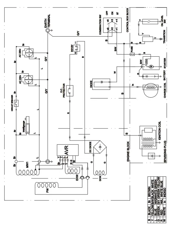
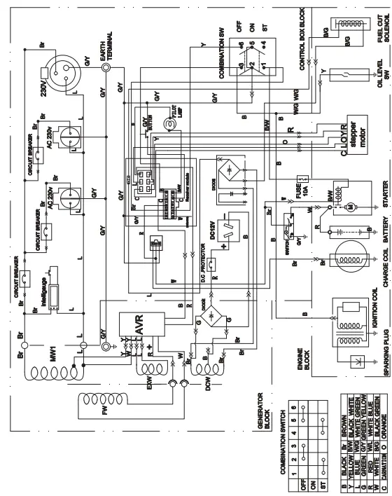
TECHNICAL DIAGRAMS
CPG2500 (EU/SC) PARTS DIAGRAM
| No. | Part Number | Description | Qty. |
| 1 | 1.5789.0608 | Flange Bolt M6 x 8 | 5 |
| 2 | 22.061100.00.2 | Cover, Recoil Starter, Black | 1 |
| 3 | 21.061005.00 | Spring, Recoil Starter | 1 |
| 4 | 2.10.003 | Rope Ø5 x 1550 | 1 |
| 5 | 21.061001.01 | Reel, Recoil Starter | 1 |
| 6 | 45.060003.00 | Spring, Ratchet | 2 |
| 7 | 45.060002.00 | Starter Ratchet, Steel | 2 |
| 8 | 45.060009.00 | Spring, Ratchet Guide | 1 |
| 9 | 45.060007.00 | Ratchet Guide | 1 |
| 10 | 45.060008.00 | Screw, Ratchet Guide | 1 |
| 11 | 24.040004.00 | Guide Plate, Push Rod | 1 |
| 12 | 1.5789.0612 | Flange Bolt M6 x 12 | 8 |
| 13 | 24.080100.01.48 | Fan Cover, Yellow | 1 |
| 14 | 24.091100.20 | Base, Air Cleaner | 1 |
| 15 | 21.061300.00 | Handle, Recoil, Soft | 1 |
| 16 | 24.130004.20 | Gasket, Air Cleaner | 1 |
| 17 | 22.061000.00 | Recoil Assembly | 1 |
| 18 | 24.091000.20 | Air Cleaner Assembly | 1 |
| 19 | 26.131000.20 | Carburetor | 1 |
| 26.131000.21 | |||
| 20 | 2.03.016 | Washer Ø10 x Ø16 x 1.5, Drain Bolt | 2 |
| 21 | 2.02.006 | Nut M14 x 1.5 | 1 |
| 22 | 21.060001.01 | Pulley, Starter | 1 |
| 23 | 23.080001.00 | Cooling Fan | 1 |
| 24 | 24.120100.06 | Flywheel | 1 |
| 25 | 2.11.001 | Oil Seal Ø25 x Ø41.3 x 6 | 2 |
| 26 | 2.03.020.1 | Washer Ø6.2 x Ø15 x 0.5, Black | 2 |
| 27 | 21.110100.00 | Gear, Governor | 1 |
| 28 | 23.130100.20 | Choke Lever | 1 |
| 29 | 21.110013.00 | Shaft, Governor Gear | 1 |
| 30 | 21.110011.00 | Clip, Governor Gear | 1 |
| 31 | 22.130003.00 | Gasket, Carburetor | 1 |
| 32 | 21.110012.01 | Bushing, Govornor Gear, Steel | 1 |
| 33 | 24.130002.00 | Gasket, Insulator | 1 |
| 34 | 23.130001.00 | Insulator, Carburetor | 1 |
| 35 | 23.080600.00 | Air Guide, Right Side | 1 |
| 36 | 2.01.003 | Stud Bolt M6 x 90 | 2 |
| 37 | 26.030100.00 | Crankcase | 1 |
| 38 | 21.127000.02 | Oil Level Sensor | 1 |
| 39 | 26.010100.00 | Cylinder Head | 1 |
| 40 | 23.050200.00 | Connecting Rod | 1 |
| 41 | 25.050100.11 | Crankshaft | 1 |
| 42 | 1.276.6205 | Bearing 6205 | 2 |
| 43 | 24.030008.00 | Gasket, Crankcase Cover | 1 |
| 44 | 22.031000.00.48 | Oil Dipstick Assembly, Yellow | 1 |
| 45 | 2.03.021.1 | Washer Ø6.4 x Ø13 x 1, Black | 1 |
| 46 | 23.030007.01 | Cover, Crankcase | 1 |
| 47 | 1.5789.0832.0.8 | Flange Bolt M8 x 32 | 6 |
| 48 | 23.091002.21 | Seal, Air Cleaner | 1 |
| 49 | 23.110006.00 | Rod, Governor | 1 |
| 50 | 21.110003.00 | Arm, Governor | 1 |
| 51 | 1.6177.06 | Flange Nut M6 | 3 |
| No. | Part Number | Description | Qty. |
| 52 | 21.110001.00 | Shaft, Governor Arm | 1 |
| 53 | 22.123000.01 | Ignition Coil, Silicon Rubber | 1 |
| 54 | 1.5789.0625 | Flange Bolt M6 x 25 | 2 |
| 55 | 23.110005.01 | Spring, Throttle Return | 1 |
| 56 | 23.110007.00 | Spring, Governor | 1 |
| 57 | 2.08.040 | Bolt M6 x 21, Governor Arm | 1 |
| 58 | 21.110008.00 | Pin, Shaft | 1 |
| 59 | 23.111000.20 | Control Assembly | 1 |
| 60 | 25.040013.00 | Lifter, Valve | 2 |
| 61 | 2.04.001 | Dowel Pin Ø9 x 14 | 2 |
| 62 | 26.041000.00 | Camshaft | 1 |
| 63 | 2.14.012 | Woodruff Key 4 x 7.5 x 19 | 1 |
| 64 | 2.08.037 | Drain Bolt M10 x 1.25 x 25 | 2 |
| 65 | 26.050005.00 | Piston | 1 |
| 66 | 23.050003.00 | Pin, Piston | 1 |
| 67 | 2.09.001 | Circlip Ø18 x Ø1 | 2 |
| 68 | 26.050303.00 | Ring, Oil | 1 |
| 69 | 26.050302.00 | Ring, Second Piston | 1 |
| 70 | 26.050301.00 | Ring, First Piston | 1 |
| 71 | 26.030009.00 | Gasket, Cylinder Head | 1 |
| 72 | 2.04.003 | Dowel Pin Ø10 x 14 | 2 |
| 73 | 23.040002.00 | Valve, Intake | 1 |
| 74 | 23.040006.00 | Valve, Exhaust | 1 |
| 75 | 26.080400.00 | Air Guide, Lower | 1 |
| 76 | 2.15.001(F6TC) | Spark Plug F6TC | 1 |
| 77 | 1.5789.0860 | Flange Bolt M8 x 60 | 4 |
| 78 | 23.040017.00 | Oil Seal, Valve, Iron | 2 |
| 79 | 21.040003.00 | Spring, Valve | 2 |
| 80 | 21.040007.00 | Retainer, Exhaust Valve Spring | 1 |
| 81 | 21.040001.00 | Retainer, Intake Valve Spring | 1 |
| 82 | 21.040008.00 | Rotator, Exhaust Valve | 1 |
| 83 | 24.040202.00 | Shaft, Rocker Arm | 1 |
| 84 | 22.040009.00 | Rocker Arm, Intake Valve | 2 |
| 85 | 22.040012.00 | Screw, Valve Adjustment | 2 |
| 86 | 21.040021.00 | Nut M6 x 0.5, Lock | 2 |
| 87 | 1.97.1.06 | Washer Ø6 | 2 |
| 88 | 1.6177.1.06 | Flange Nut M6 | 2 |
| 89 | 26.131017.20 | Main Jet, Standard | 1 |
| 26.131017.20.01 | Main Jet, Altitude | / | |
| 90 | 24.040201.00 | Retainer, Rocker Arm | 1 |
| 91 | 23.040010.00 | Bolt, Rocker Arm | 2 |
| 92 | 23.040005.00 | Push Rod | 2 |
| 93 | 21.020002.01 | Gasket, Cylinder Head Cover | 1 |
| 94 | 24.021000.00 | Cover, Cylinder Head | 1 |
| 95 | 23.020001.02 | Breather Tube | 1 |
| 96 | 1.5789.0615 | Flange Bolt M6 x 15 | 4 |
| 97 | 2.01.010 | Stud Bolt M8 x 35 | 2 |
| 98 | 1.5789.0620 | Flange Bolt M6 x 20 | 1 |
| 99 | 24.091200.20 | Cover, Air Cleaner | 1 |
| 100 | 23.091003.21 | Element, Air Cleaner | 1 |
| 101 | 23.091001.21 | Separator, Air Cleaner | 1 |
CPG2500 (EU/SC) PARTS DIAGRAM
| No | Part Number | Description | QTY |
| 1 | CPG2500 | Engine | 1 |
| 2 | 122.190005.00 | Rubber, Fore-Cover, B | 1 |
| 3 | 122.190005.01 | Rubber, Fore-Cover, A | 1 |
| 4 | 122.191100.00 | Rotor Assembly, Cu, Ø95 x 85 mm | 1 |
| 5 | 2.08.017 | Flange Bolt M8 x 208 | 1 |
| 6 | 122.191200.08 | Stator Assembly, Cu, Ø160 x 85 mm | 1 |
| 7 | 122.191002.00 | Cover, Stator | 1 |
| 8 | 122.190002.00 | End Housing | 1 |
| 9 | 2.08.050 | Flange Bolt M6 x 133 | 4 |
| 10 | 1.16674.0512.2 | Flange Bolt M5×12 | 3 |
| 11 | 122.190600.00 | Rectifier | 1 |
| 12 | 1.16674.0520 | Flange Bolt M5×20 | 1 |
| 13 | 122.190400.00 | Terminal Block | 1 |
| 14 | 1.5783.0516 | Bolt M5 x 16 | 3 |
| 15 | 122.190200.00 | AVR | 1 |
| 16 | 1.16674.0516 | Flange Bolt M5 x 16 | 2 |
| 17 | 122.190003.00.48 | End Cover, Generator, Yellow | 1 |
| 18 | 1.9074.15.0520 | Washer Assembly M5 x 20 | 1 |
| 19 | 122.190004.01 | Pinch, Carbon Brush | 1 |
| 20 | 122.190300.00 | Carbon Brush Assembly | 1 |
| 21 | 1.5789.0615 | Flange Bolt M6 x 15 | 3 |
| 22 | 27.100100.10 | Bracket, Muffler | 1 |
| 23 | 1.823.0406 | Screw M4 x 6 | 3 |
| 24 | 27.101300.00 | Spark Arrester Assembly | 1 |
| 25 | 27.101000.01.2 | Muffler Assembly | 1 |
| 26 | 1.6175.08 | Nut M8 | 2 |
| 27 | 1.93.08 | Lock Washer Ø8 | 2 |
| 28 | 1.848.08 | Washer Ø8 | 2 |
| 29 | 21.100001.00 | Gasket, Exhaust | 1 |
| 30 | 1.5789.0608 | Flange Bolt M6 x 8 | 1 |
| 31 | 23.090006.21 | Holder, Air Cleaner | 1 |
| 32 | 122.071000.45.48 | Fuel Tank, Yellow | 1 |
| 33 | 1.93.06 | Lock Washer Ø6 | 4 |
| 34 | 122.070015.01 | Mount Vibration, Fuel Tank | 4 |
| 35 | 2.03.004.1 | Washer Ø24 x Ø6.5 x 1.5, Black | 4 |
| 36 | 1.5789.0620.1 | Flange Bolt M6 x 20, Black | 4 |
| 37 | 122.070300.02 | Fuel Filter, Fuel Tank | 1 |
| 38 | 122.070100.02 | Cap, Fuel Tank | 1 |
| 39 | 1.819.0510 | Screw M5×10 | 2 |
| 40 | 122.072000.01 | Fuel Meter Assembly | 1 |
| No | Part Number | Description | QTY |
| 41 | 2.06.007 | Clamp Ø8 x b6 | 2 |
| 42 | 122.070011.04 | Fuel Pipe Ø4.5 x Ø8.5 x 140 mm | 1 |
| 43 | 122.070400.04 | Fuel Valve | 1 |
| 44 | 1.6177.1.08 | Lock Nut M8, Flange | 12 |
| 45 | 62337.2.2.2 | Frame | 1 |
| 46 | 122.201200.00 | Mount 2, Motor | 2 |
| 47 | 122.201200.01 | Mount 1, Motor | 2 |
| 48 | 122.201400.01 | Rubber | 4 |
| 49 | 1.62.06 | Butterfly Type Nut M6 | 1 |
| 50 | 1.93.06.2 | Lock Waher Ø6 | 1 |
| 51 | 1.97.1.06.2 | Washer Ø6 | 2 |
| 52 | 1.6177.1.06 | Lock Nut M6, Flange | 1 |
| 53 | 5.1900.026 | Grounding Line 150 mm | 1 |
| 54 | 1.862.06 | Lock Washer Ø6, Toothed | 1 |
| 55 | 122.210007.26 | Control Box | 1 |
| 56 | 1.5789.0615.1 | Bolt M6 x 15, Black | 4 |
| 57 | 1.818.0514.2 | Screw M5 x 14 | 1 |
| 58 | 5.1810.001 | Over Voltage Protector | 1 |
| 59 | 122.20.11.48 | Control Panel, Yellow | 1 |
| 60 | 5.1000.004.3 | Ignition Switch, Red | 1 |
| 61 | 1.9074.4.0512.1 | Screw/Washer Assembly M5 x 12, Black | 5 |
| 62 | 5.1400.003 | Voltage Meter | 1 |
| 63 | 1.848.03.2 | Washer Ø3 | 4 |
| 64 | 1.859.03.2 | Lock Washer Ø3 | 4 |
| 65 | 1.6175.03.2 | Nut M3 | 4 |
| 66 | 5.1240.091 | Double Pole Circuit Breaker | 1 |
| 67 | 5.1120.009 | Receptacle L14-30R | 1 |
| 68 | 5.1120.008 | Receptacle L5-30R | 1 |
| 69 | 1.6177.1.04.1 | Nut M4 | 6 |
| 70 | 5.1120.010 | Receptacle 5-20R, Duplex | 1 |
| 71 | 5.1200.110 | 10Amp Circuit Breaker, Push Button | 1 |
| 72 | 5.1110.001 | Receptacle | 1 |
| 73 | CPG2500.21.10 | Wire Assembly | 1 |
| 74 | 122.210003.01 | Wire Jacket, Control Box | 1 |
| 75 | 5.1330.001 | Sheath, Wire | 1 |
| 76 | 122.210003.03 | Plug, End Cover | 1 |
| 77 | CPG2500.21 | Control Panel Assembly | 1 |
CPG3500 (EU/SC) PARTS DIAGRAM
| No. | Part Number | Description | Qty. |
| 1 | 1.5789.0608 | Flange Bolt M6 x 8 | 5 |
| 2 | 22.061100.00.2 | Cover, Recoil Starter, Black | 1 |
| 3 | 21.061005.00 | Spring, Recoil Starter | 1 |
| 4 | 2.10.003 | Rope Ø5 x 1550 | 1 |
| 5 | 21.061001.01 | Reel, Recoil Starter | 1 |
| 6 | 45.060003.00 | Spring, Ratchet | 2 |
| 7 | 45.060002.00 | Starter Ratchet, Steel | 2 |
| 8 | 45.060009.00 | Spring, Ratchet Guide | 1 |
| 9 | 45.060007.00 | Ratchet Guide | 1 |
| 10 | 45.060008.00 | Screw, Ratchet Guide | 1 |
| 11 | 24.040004.00 | Guide Plate, Push Rod | 1 |
| 12 | 1.5789.0612 | Flange Bolt M6 x 12 | 8 |
| 13 | 24.080100.01.48 | Fan Cover, Yellow | 1 |
| 14 | 24.091100.20 | Base, Air Cleaner | 1 |
| 15 | 21.061300.00 | Handle, Recoil, Soft | 1 |
| 16 | 24.130004.20 | Gasket, Air Cleaner | 1 |
| 17 | 22.061000.00 | Recoil Assembly | 1 |
| 18 | 24.091000.20 | Air Cleaner Assembly | 1 |
| 19 | 26.131000.20 | Carburetor | 1 |
| 26.131000.21 | |||
| 20 | 2.03.016 | Washer Ø10 x Ø16 x 1.5, Drain Bolt | 2 |
| 21 | 2.02.006 | Nut M14 x 1.5 | 1 |
| 22 | 21.060001.01 | Pulley, Starter | 1 |
| 23 | 23.080001.00 | Cooling Fan | 1 |
| 24 | 24.120100.06 | Flywheel | 1 |
| 25 | 2.11.001 | Oil Seal Ø25 x Ø41.3 x 6 | 2 |
| 26 | 2.03.020.1 | Washer Ø6.2 x Ø15 x 0.5, Black | 2 |
| 27 | 21.110100.00 | Gear, Governor | 1 |
| 28 | 23.130100.20 | Choke Lever | 1 |
| 29 | 21.110013.00 | Shaft, Governor Gear | 1 |
| 30 | 21.110011.00 | Clip, Governor Gear | 1 |
| 31 | 22.130003.00 | Gasket, Carburetor | 1 |
| 32 | 21.110012.01 | Bushing, Govornor Gear, Steel | 1 |
| 33 | 24.130002.00 | Gasket, Insulator | 1 |
| 34 | 23.130001.00 | Insulator, Carburetor | 1 |
| 35 | 23.080600.00 | Air Guide, Right Side | 1 |
| 36 | 2.01.003 | Stud Bolt M6 x 90 | 2 |
| 37 | 26.030100.00 | Crankcase | 1 |
| 38 | 21.127000.02 | Oil Level Sensor | 1 |
| 39 | 26.010100.00 | Cylinder Head | 1 |
| 40 | 23.050200.00 | Connecting Rod | 1 |
| 41 | 25.050100.11 | Crankshaft | 1 |
| 42 | 1.276.6205 | Bearing 6205 | 2 |
| 43 | 24.030008.00 | Gasket, Crankcase Cover | 1 |
| 44 | 22.031000.00.48 | Oil Dipstick Assembly, Yellow | 1 |
| 45 | 2.03.021.1 | Washer Ø6.4 x Ø13 x 1, Black | 1 |
| 46 | 23.030007.01 | Cover, Crankcase | 1 |
| 47 | 1.5789.0832.0.8 | Flange Bolt M8 x 32 | 6 |
| 48 | 23.091002.21 | Seal, Air Cleaner | 1 |
| 49 | 23.110006.00 | Rod, Governor | 1 |
| 50 | 21.110003.00 | Arm, Governor | 1 |
| 51 | 1.6177.06 | Flange Nut M6 | 3 |
| No. | Part Number | Description | Qty. |
| 52 | 21.110001.00 | Shaft, Governor Arm | 1 |
| 53 | 22.123000.01 | Ignition Coil, Silicon Rubber | 1 |
| 54 | 1.5789.0625 | Flange Bolt M6 x 25 | 2 |
| 55 | 23.110005.01 | Spring, Throttle Return | 1 |
| 56 | 23.110007.00 | Spring, Governor | 1 |
| 57 | 2.08.040 | Bolt M6 x 21, Governor Arm | 1 |
| 58 | 21.110008.00 | Pin, Shaft | 1 |
| 59 | 23.111000.20 | Control Assembly | 1 |
| 60 | 25.040013.00 | Lifter, Valve | 2 |
| 61 | 2.04.001 | Dowel Pin Ø9 x 14 | 2 |
| 62 | 26.041000.00 | Camshaft | 1 |
| 63 | 2.14.012 | Woodruff Key 4 x 7.5 x 19 | 1 |
| 64 | 2.08.037 | Drain Bolt M10 x 1.25 x 25 | 2 |
| 65 | 26.050005.00 | Piston | 1 |
| 66 | 23.050003.00 | Pin, Piston | 1 |
| 67 | 2.09.001 | Circlip Ø18 x Ø1 | 2 |
| 68 | 26.050303.00 | Ring, Oil | 1 |
| 69 | 26.050302.00 | Ring, Second Piston | 1 |
| 70 | 26.050301.00 | Ring, First Piston | 1 |
| 71 | 26.030009.00 | Gasket, Cylinder Head | 1 |
| 72 | 2.04.003 | Dowel Pin Ø10 x 14 | 2 |
| 73 | 23.040002.00 | Valve, Intake | 1 |
| 74 | 23.040006.00 | Valve, Exhaust | 1 |
| 75 | 26.080400.00 | Air Guide, Lower | 1 |
| 76 | 2.15.001(F6TC) | Spark Plug F6TC | 1 |
| 77 | 1.5789.0860 | Flange Bolt M8 x 60 | 4 |
| 78 | 23.040017.00 | Oil Seal, Valve, Iron | 2 |
| 79 | 21.040003.00 | Spring, Valve | 2 |
| 80 | 21.040007.00 | Retainer, Exhaust Valve Spring | 1 |
| 81 | 21.040001.00 | Retainer, Intake Valve Spring | 1 |
| 82 | 21.040008.00 | Rotator, Exhaust Valve | 1 |
| 83 | 24.040202.00 | Shaft, Rocker Arm | 1 |
| 84 | 22.040009.00 | Rocker Arm, Intake Valve | 2 |
| 85 | 22.040012.00 | Screw, Valve Adjustment | 2 |
| 86 | 21.040021.00 | Nut M6 x 0.5, Lock | 2 |
| 87 | 1.97.1.06 | Washer Ø6 | 2 |
| 88 | 1.6177.1.06 | Flange Nut M6 | 2 |
| 89 | 26.131017.20 | Main Jet, Standard | 1 |
| 26.131017.20.01 | Main Jet, Altitude | / | |
| 90 | 24.040201.00 | Retainer, Rocker Arm | 1 |
| 91 | 23.040010.00 | Bolt, Rocker Arm | 2 |
| 92 | 23.040005.00 | Push Rod | 2 |
| 93 | 21.020002.01 | Gasket, Cylinder Head Cover | 1 |
| 94 | 24.021000.00 | Cover, Cylinder Head | 1 |
| 95 | 23.020001.02 | Breather Tube | 1 |
| 96 | 1.5789.0615 | Flange Bolt M6 x 15 | 4 |
| 97 | 2.01.010 | Stud Bolt M8 x 35 | 2 |
| 98 | 1.5789.0620 | Flange Bolt M6 x 20 | 1 |
| 99 | 24.091200.20 | Cover, Air Cleaner | 1 |
| 100 | 23.091003.21 | Element, Air Cleaner | 1 |
| 101 | 23.091001.21 | Separator, Air Cleaner | 1 |
CPG3500 (EU/SC) PARTS DIAGRAM
| No | Part Number | Description | QTY |
| 1 | CPG3500 | Engine | 1 |
| 2 | 122.190005.00 | Rubber, Fore-Cover, B | 1 |
| 3 | 122.190005.01 | Rubber, Fore-Cover, A | 1 |
| 4 | 123.191100.04 | Rotor Assembly, Cu, Ø160 x 110 mm | 1 |
| 5 | 2.08.021 | Flange Bolt M8 x 233 | 1 |
| 6 | 123.191200.04 | Stator Assembly, Cu, Ø160 x 110 mm | 1 |
| 7 | 122.191002.00 | Cover, Stator | 1 |
| 8 | 122.190002.00 | End Housing | 1 |
| 9 | 2.08.020 | Flange Bolt M6 x 158 | 4 |
| 10 | 1.16674.0512.2 | Flange Bolt M5×12 | 3 |
| 11 | 122.190600.00 | Rectifier | 1 |
| 12 | 1.16674.0520 | Flange Bolt M5×20 | 1 |
| 13 | 122.190400.00 | Terminal Block | 1 |
| 14 | 1.5783.0516 | Bolt M5 x 16 | 3 |
| 15 | 122.190200.00 | AVR | 1 |
| 16 | 1.16674.0516 | Flange Bolt M5 x 16 | 2 |
| 17 | 122.190003.00.48 | End Cover, Generator, Yellow | 1 |
| 18 | 1.9074.15.0520 | Washer Assembly M5 x 20 | 1 |
| 19 | 122.190004.01 | Pinch, Carbon Brush | 1 |
| 20 | 122.190300.00 | Carbon Brush Assembly | 1 |
| 21 | 1.5789.0615 | Flange Bolt M6 x 15 | 3 |
| 22 | 27.100100.10 | Bracket, Muffler | 1 |
| 23 | 1.823.0406 | Screw M4 x 6 | 3 |
| 24 | 27.101300.00 | Spark Arrester Assembly | 1 |
| 25 | 27.101000.01.2 | Muffler Assembly | 1 |
| 26 | 1.6175.08 | Nut M8 | 2 |
| 27 | 1.93.08 | Lock Washer Ø8 | 2 |
| 28 | 1.848.08 | Washer Ø8 | 2 |
| 29 | 21.100001.00 | Gasket, Exhaust | 1 |
| 30 | 1.5789.0608 | Flange Bolt M6 x 8 | 1 |
| 31 | 23.090006.21 | Holder, Air Cleaner | 1 |
| 32 | 122.071000.45.48 | Fuel Tank, Yellow | 1 |
| 33 | 1.93.06 | Lock Washer Ø6 | 4 |
| 34 | 122.070015.01 | Mount Vibration, Fuel Tank | 4 |
| 35 | 2.03.004.1 | Washer Ø24 x Ø6.5 x 1.5, Black | 4 |
| 36 | 1.5789.0620.1 | Flange Bolt M6 x 20, Black | 4 |
| 37 | 122.070300.02 | Fuel Filter, Fuel Tank | 1 |
| 38 | 122.070100.02 | Cap, Fuel Tank | 1 |
| 39 | 1.819.0510 | Screw M5×10 | 2 |
| No | Part Number | Description | QTY |
| 40 | 122.072000.01 | Fuel Meter Assembly | 1 |
| 41 | 2.06.007 | Clamp Ø8 x b6 | 2 |
| 42 | 122.070011.04 | Fuel Pipe Ø4.5 x Ø8.5 x 140 mm | 1 |
| 43 | 122.070400.04 | Fuel Valve | 1 |
| 44 | 1.6177.1.08 | Lock Nut M8, Flange | 12 |
| 45 | 62337.2.5.2 | Frame | 1 |
| 46 | 122.201200.00 | Mount 2, Motor | 2 |
| 47 | 122.201200.01 | Mount 1, Motor | 2 |
| 48 | 122.201400.01 | Rubber | 4 |
| 49 | 1.62.06 | Butterfly Type Nut M6 | 1 |
| 50 | 1.93.06.2 | Lock Waher Ø6 | 1 |
| 51 | 1.97.1.06.2 | Washer Ø6 | 2 |
| 52 | 1.6177.1.06 | Lock Nut M6, Flange | 1 |
| 53 | 5.1900.026 | Grounding Line 150 mm | 1 |
| 54 | 1.862.06 | Lock Washer Ø6, Toothed | 1 |
| 55 | 122.210007.26 | Control Box | 1 |
| 56 | 1.5789.0615.1 | Bolt M6 x 15, Black | 4 |
| 57 | 1.818.0514.2 | Screw M5 x 14 | 1 |
| 58 | 5.1810.001 | Over Voltage Protector | 1 |
| 59 | 122.20.11.48 | Control Panel, Yellow | 1 |
| 60 | 5.1000.004.3 | Ignition Switch, Red | 1 |
| 61 | 1.9074.4.0512.1 | Screw/Washer Assembly M5 x 12, Black | 5 |
| 62 | 5.1400.003 | Voltage Meter | 1 |
| 63 | 1.848.03.2 | Washer Ø3 | 4 |
| 64 | 1.859.03.2 | Lock Washer Ø3 | 4 |
| 65 | 1.6175.03.2 | Nut M3 | 4 |
| 66 | 5.1240.117 | Double Pole Circuit Breaker | 1 |
| 67 | 5.1120.009 | Receptacle L14-30R | 1 |
| 68 | 5.1120.008 | Receptacle L5-30R | 1 |
| 69 | 1.6177.1.04.1 | Nut M4 | 6 |
| 70 | 5.1120.010 | Receptacle 5-20R, Duplex | 1 |
| 71 | 5.1200.110 | 10Amp Circuit Breaker, Push Button | 1 |
| 72 | 5.1110.001 | Receptacle | 1 |
| 73 | CPG3500.21.10 | Wire Assembly | 1 |
| 74 | 122.210003.01 | Wire Jacket, Control Box | 1 |
| 75 | 5.1330.001 | Sheath, Wire | 1 |
| 76 | 122.210003.03 | Plug, End Cover | 1 |
| 77 | CPG3500.21 | Control Panel Assembly | 1 |
CPG4000 E1 (EU/SC) PARTS DIAGRAM
| No. | Part Number | Description | Qty |
| 1 | 1.5789.0608 | Flange Bolt M6 × 8 | 6 |
| 2 | 22.061100.00.2 | Cover, Recoil Starter, Black | 1 |
| 3 | 21.061005.00 | Spring, Recoil Starter | 1 |
| 4 | 2.10.003 | Rope Ø5 × 1550 | 1 |
| 5 | 21.061001.01 | Reel, Recoil Starter | 1 |
| 6 | 45.060003.00 | Spring, Ratchet | 2 |
| 7 | 45.060002.00 | Starter Ratchet, Steel | 2 |
| 8 | 45.060009.00 | Spring, Ratchet Guide | 1 |
| 9 | 45.060007.00 | Ratchet Guide | 1 |
| 10 | 45.060008.00 | Screw, Ratchet Guide | 1 |
| 11 | 24.040004.00 | Guide Plate, Push Rod | 1 |
| 12 | 1.5789.0612 | Flange Bolt M6 × 12 | 8 |
| 13 | 27.080100.01.48 | Fan Cover, Yellow | 1 |
| 14 | 24.091100.20 | Base, Air Cleaner | 1 |
| 15 | 21.061300.00 | Handle, Recoil, Soft | 1 |
| 16 | 24.130004.20 | Gasket, Air Cleaner | 1 |
| 17 | 22.061000.00 | Recoil Assembly | 1 |
| 18 | 27.091000.01 | Air Cleaner Assembly | 1 |
| 19 | 27.131000.01 | Carburetor | 1 |
| 27.131000.06 | |||
| 20 | 2.03.016 | Washer Ø10 × Ø16 × 1.5, Drain Bolt | 2 |
| 21 | 2.02.006 | Nut M14 × 1.5 | 1 |
| 22 | 83.060001.01 | Pulley, Starter | 1 |
| 23 | 27.080001.00 | Cooling Fan | 1 |
| 24 | 24.120100.07 | Flywheel | 1 |
| 25 | 2.11.001 | Oil Seal Ø25 × Ø41.3 × 6 | 2 |
| 26 | 2.03.020.1 | Washer Ø6.2 × Ø15 × 0.5, Black | 2 |
| 27 | 21.110100.00 | Gear, Governor | 1 |
| 28 | 23.130100.20 | Choke Lever | 1 |
| 29 | 21.110013.00 | Shaft, Governor Gear | 1 |
| 30 | 21.110011.00 | Clip, Governor Gear | 1 |
| 31 | 22.130003.00 | Gasket, Carburetor | 1 |
| 32 | 21.110012.01 | Bushing, Govornor Gear, Steel | 1 |
| 33 | 24.130002.00 | Gasket, Insulator | 1 |
| 34 | 27.130001.00 | Insulator, Carburetor | 1 |
| 35 | 27.080600.01 | Air Guide, Right Side | 1 |
| 36 | 2.01.003 | Stud Bolt M6 × 90 | 2 |
| 37 | 27.030100.00 | Crankcase | 1 |
| 38 | 21.127000.02 | Oil Level Sensor | 1 |
| 39 | 26.010100.01 | Cylinder Head, 224cc | 1 |
| 40 | 27.050200.00 | Connecting Rod | 1 |
| 41 | 27.050100.00 | Crankshaft | 1 |
| 42 | 1.276.6205 | Bearing 6205 | 2 |
| 43 | 24.030008.00 | Gasket, Crankcase Cover | 1 |
| 44 | 46.031000.00 | Oil Dipstick Assembly, Black | 1 |
| 45 | 2.03.021.1 | Washer Ø6.4 × Ø13 × 1, Black | 1 |
| 46 | 23.030007.01 | Cover, Crankcase | 1 |
| 47 | 1.5789.0832.0.8 | Flange Bolt M8 × 32 | 6 |
| 48 | 23.091002.21 | Seal, Air Cleaner | 1 |
| 49 | 23.110006.00 | Rod, Governor | 1 |
| 50 | 27.110003.00 | Arm, Governor | 1 |
| 51 | 1.6177.06 | Flange Nut M6 | 3 |
| 52 | 21.110001.00 | Shaft, Governor Arm | 1 |
| 53 | 22.123000.01 | Ignition Coil, Silicon Rubber | 1 |
| 54 | 1.5789.0625 | Flange Bolt M6 × 25 | 5 |
| 55 | 23.110005.01 | Spring, Throttle Return | 1 |
| 56 | 23.110007.00 | Spring, Governor | 1 |
| 57 | 2.08.040 | Bolt M6 × 21, Governor Arm | 1 |
| No. | Part Number | Description | Qty |
| 58 | 21.110008.00 | Pin, Shaft | 1 |
| 59 | 27.111000.20 | Control Assembly | 1 |
| 60 | 25.040013.00 | Lifter, Valve | 2 |
| 61 | 2.04.001 | Dowel Pin Ø9 × 14 | 2 |
| 62 | 27.041000.00 | Camshaft | 1 |
| 63 | 2.14.012 | Woodruff Key 4 × 7.5 × 19 | 1 |
| 64 | 2.08.037 | Drain Bolt M10 × 1.25 × 25 | 2 |
| 65 | 27.050005.00 | Piston | 1 |
| 66 | 23.050003.00 | Pin, Piston | 1 |
| 67 | 2.09.001 | Circlip Ø18 × Ø1 | 2 |
| 68 | 27.050303.00 | Ring, Oil | 1 |
| 69 | 27.050302.00 | Ring, Second Piston | 1 |
| 70 | 27.050301.00 | Ring, First Piston | 1 |
| 71 | 27.030009.01 | Gasket, Cylinder Head | 1 |
| 72 | 2.04.003 | Dowel Pin Ø10 × 14 | 2 |
| 73 | 23.040002.02 | Valve, Intake | 1 |
| 74 | 23.040006.02 | Valve, Exhaust | 1 |
| 75 | 26.080400.00 | Air Guide, Lower | 1 |
| 76 | 2.15.001(F6TC) | Spark Plug F6TC | 1 |
| 77 | 1.5789.0865 | Flange Bolt M8 × 65 | 3 |
| 78 | 23.040017.00 | Oil Seal, Valve, Iron | 2 |
| 79 | 21.040003.00 | Spring, Valve | 2 |
| 80 | 21.040007.00 | Retainer, Exhaust Valve Spring | 1 |
| 81 | 21.040001.00 | Retainer, Intake Valve Spring | 1 |
| 82 | 21.040008.00 | Rotator, Exhaust Valve | 1 |
| 83 | 24.040202.00 | Shaft, Rocker Arm | 1 |
| 84 | 22.040009.00 | Rocker Arm, Intake Valve | 2 |
| 85 | 22.040012.00 | Screw, Valve Adjustment | 2 |
| 86 | 21.040021.00 | Nut M6 × 0.5, Lock | 2 |
| 87 | 1.97.1.06 | Washer Ø6 | 2 |
| 88 | 1.6177.1.06 | Flange Nut M6 | 2 |
| 89 | 27.131017.01 | Main Jet, Standard | 1 |
| 27.131017.01.01 | Main Jet, Altitude | / | |
| 90 | 24.040201.00 | Retainer, Rocker Arm | 1 |
| 91 | 23.040010.00 | Bolt, Rocker Arm | 2 |
| 92 | 27.040005.00 | Push Rod | 2 |
| 93 | 21.020002.01 | Gasket, Cylinder Head Cover | 1 |
| 94 | 24.021000.00 | Cover, Cylinder Head | 1 |
| 95 | 23.020001.02 | Breather Tube | 1 |
| 96 | 1.5789.0615 | Flange Bolt M6 × 15 | 4 |
| 97 | 2.01.010 | Stud Bolt M8 × 35 | 2 |
| 98 | 21.120400.00 | Diode Comp | 1 |
| 99 | 27.091200.01 | Cover, Air Cleaner | 1 |
| 100 | 23.091003.21 | Element, Air Cleaner | 1 |
| 101 | 23.091001.21 | Separator, Air Cleaner | 1 |
| 102 | 122.070011.04 | Pipe, Fuel 140 | 1 |
| 103 | 2.06.007 | Clamp Ø8 × b6 | 2 |
| 104 | 152.070031.01 | Sheath, Wire | 1 |
| 105 | 2.08.121 | Flange Bolt M10 × 65 | 1 |
| 106 | 1.5789.0629 | Flange Bolt M6 × 29 | 1 |
| 107 | 2.04.005 | Dowel Pin, Ø8 × 10 | 2 |
| 108 | 27.125100.00 | Starter Motor Assembly | 1 |
| 109 | 1.93.05 | Lock Washer Ø5 | 2 |
| 110 | 1.16674.0516 | Flange Bolt M5 × 16 | 2 |
| 111 | 23.125200.03 | Relay, Starter | 1 |
| 112 | 45.121000.00 | Coil, Charging | 1 |
| 113 | 23.030006.00 | Plate, Coil | 1 |
CPG4000 E1 (EU/SC) PARTS DIAGRAM
| No | Part Number | Destription | QTY |
| 1 | CPG4000E1-EU | Engine | 1 |
| 2 | 122.190005.00 | Rubber, Fore-Cover, B | 1 |
| 3 | 122.190005.01 | Rubber, Fore-Cover, A | 1 |
| 4 | 124.191100.00 | Rotor Assembly | 1 |
| 5 | 2.08.022 | Flange Bolt M8 x 242 | 1 |
| 6 | 124.191200.00 | Stator Assembly | 1 |
| 7 | 123.191002.00 | Stator Cover | 1 |
| 8 | 122.190002.00 | End Housing | 1 |
| 9 | 2.08.065 | Flange Bolt M6 x 168 | 4 |
| 10 | 122.190300.00 | Carbon Brush Assembly | 1 |
| 11 | 122.190600.00 | Diode Assembly | 1 |
| 12 | 1.5783.0520 | Bolt M5 x 20 | 1 |
| 13 | 1.93.05 | Spring Washer ij5 | 2 |
| 14 | 1.5783.0516 | Bolt M5 x 16 | 1 |
| 15 | 1.9074.17.0516 | Screw/Washer Assembly M5 x 16 | 2 |
| 16 | 122.190200.00 | AVR | 1 |
| 17 | 1.16674.0516 | Flange Bolt M5 x 16 | 2 |
| 18 | 122.190003.00.48 | Generator End Cover Yellow | 1 |
| 19 | 1.16674.0512.2 | Flange Bolt M5 x 12 | 3 |
| 20 | 122.190400.00 | Terminal Block | 1 |
| 21 | 122.190004.01 | Pinch | 1 |
| 22 | 122.190018.00 | Bracket,Muffler | 1 |
| 23 | 1.16674.0820 | Flange Bolt M8 x 20 | 3 |
| 24 | 122.190018.01 | Bracket,Muffler | 1 |
| 25 | 1.5789.0612 | Flange Bolt M6 x 12 | 13 |
| 26 | 1.9074.4.0514 | Screw And Washer Assembly M5 x 14 | 2 |
| 27 | 46.101503.08 | Plate, Spark Arrester | 1 |
| 28 | 46.101300.08 | Spark Arrester Assembly | 1 |
| 29 | 26.101000.00 | Muffler | 1 |
| 30 | 23.102000.03.2 | Muffler Cover | 1 |
| 31 | 1.6175.08 | Nut M8 | 2 |
| 32 | 1.93.08 | Spring Washer ij8 | 4 |
| 33 | 1.848.08 | Washer ĭ8 | 2 |
| 34 | 21.100001.00 | Muffler Gasket | 1 |
| 35 | 23.090006.21 | Holder,Air Cleaner | 1 |
| 36 | 1.5789.0608 | Flange Bolt M6 x 8 | 4 |
| 37 | 122.070011.05 | Pipe,Fuel(5.5in) | 1 |
| 38 | 2.06.007 | Clamp | 2 |
| 39 | 122.070400.03 | Fuel Cock | 1 |
| 40 | 122.071000.06.48 | Fuel Tank Yellow | 1 |
| 41 | 122.070015.01 | Mount Vibration, Fuel Tank | 4 |
| 42 | 2.03.004 | Washer ĭ6 | 4 |
| 43 | 1.93.06 | Spring Washer ij6 | 4 |
| 44 | 1.5789.0620.2 | Flange Bolt M6 x 20 | 4 |
| 45 | 122.072000.02 | Fuel Meter Assembly | 1 |
| 46 | 1.819.0510 | Screw M5 x 10 | 2 |
| No | Part Number | Description | QTY |
| 47 | 122.070300.02 | Fuel Filter | 1 |
| 48 | 122.070100.03 | Fuel Tank Cap | 1 |
| 49 | 62294.2.15.2 | Frame | 1 |
| 50 | 1.6177.1.08 | Nut M8 | 12 |
| 51 | 122.201200.01 | Motor Mount 1 | 1 |
| 52 | 122.201200.00 | Motor Mount 2 | 1 |
| 53 | 1.5789.0835 | Flange Bolt M8 x 35 | 2 |
| 54 | 1.96.08 | Big Whashe ij8 | 2 |
| 55 | 152.201200.00 | Motor Mount | 2 |
| 56 | 122.201400.01 | Rubber | 4 |
| 57 | 1.6177.1.06 | Nut M6 | 3 |
| 58 | 5.1900.026 | Grounding Line | 1 |
| 59 | 1.862.06 | Lock Washer ĭ6 | 2 |
| 60 | 1.9074.3.0510 | Bolt And Washer Assembly M5 x 10 | 2 |
| 61 | 1.6177.1.05 | Flange Lock Nut M5 | 2 |
| 62 | 9.1000.075 | Battery 12V 7.5AH | 1 |
| 63 | 122.200901.02 | Supporter,Battery | 1 |
| 64 | 122.200902.01 | Lock,Battery | 1 |
| 65 | 1.5789.0845 | Flange Bolt M8 x 45 | 2 |
| 66 | 5.1900.009 | Black Wire,Battery | 1 |
| 67 | 5.1900.010 | Red Wire,Battery | 1 |
| 68 | 152.200013.01.3 | Jacket, Red | 2 |
| 69 | 152.200013.01 | Jacket, Black | 1 |
| 70 | 122.159.9.2 | Control Panel | 1 |
| 71 | 5.1000.001.3 | Switch | 1 |
| 72 | 5.1120.013.1 | Receptacle | 2 |
| 73 | 1.819.0414.2 | Screw M4 x 14 | 8 |
| 74 | 1.5783.0622.2 | Bolt M6 x 22 | 1 |
| 75 | 1.6175.06.2 | Nut M6 | 2 |
| 76 | 1.93.06.2 | Spring Washer ĭ6 | 2 |
| 77 | 1.97.1.06.2 | Washer ĭ6 | 2 |
| 78 | 5.1110.001 | Receptacle DC.12V | 1 |
| 79 | 5.1200.110.1 | AC.10A Breaker | 1 |
| 80 | 1.6177.1.04.2 | Flange Nut M4 | 10 |
| 81 | 5.1220.130 | AC.13A Breaker | 1 |
| 82 | 1.9074.4.0306.2 | Bolt and Washer Assembly M3 x 6 | 2 |
| 83 | 1.9074.4.0414.2 | Bolt and Washer Assembly M4 x 14 | 2 |
| 84 | 5.1430.002 | Intelligauge | 1 |
| 85 | 5.1800.002 | Rectifier | 1 |
| 86 | 122.210002.14 | Control Box | 1 |
| 87 | 1.9074.1.0538.2 | Bolt and Washer Assembly M5 x 38 | 3 |
| 88 | 122.210003.00 | sheath,wire | 1 |
| 89 | 122.210003.01 | Plug, Control Box | 1 |
| 90 | 5.1330.214 | Plug | 1 |
| 91 | 122.210003.03 | Plug, End Cover | 1 |
CPG6500 E2 (EU/SC) PARTS DIAGRAM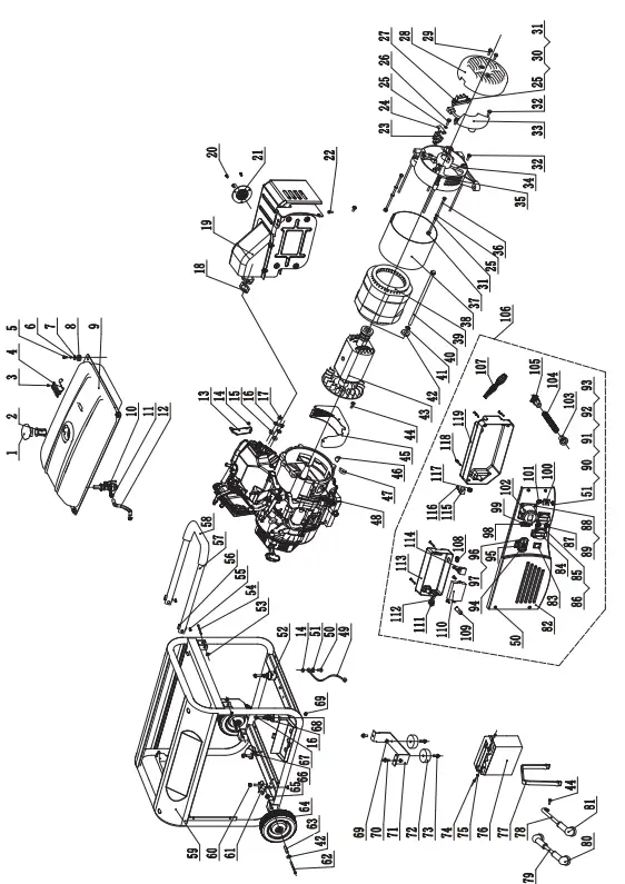
| No | Part Number | Destription | QTY |
| 1 | 122.070100.03 | Fuel Tank Cap | 1 |
| 2 | 122.070300.02 | Fuel Filter | 1 |
| 3 | 1.819.0510 | Screw M5 x 10 | 2 |
| 4 | 152.072000.03 | Fuel Meter Assembly | 1 |
| 5 | 1.5789.0620.2 | Flange Bolt M6 x 20 | 4 |
| 6 | 1.93.06 | Spring Washer ĭ 6 | 4 |
| 7 | 2.03.004 | Washer ĭ 6 | 4 |
| 8 | 122.070015.01 | Mount Vibration, Fuel Tank | 4 |
| 9 | 152.071000.03.48 | Fuel Tank | 1 |
| 10 | 122.070400.03 | Fuel Cock | 1 |
| 11 | 2.06.007 | Clamp | 2 |
| 12 | 152.070011.06 | Pipe,Fuel 170 mm | 1 |
| 13 | 45.090006.20 | Holder, Air Cleaner | 1 |
| 14 | 1.6177.1.06 | Nut M 6 | 2 |
| 15 | 1.848.08 | Washer ĭ 8 | 2 |
| 16 | 1.93.08 | Spring Washer ĭ 8 | 4 |
| 17 | 1.6175.08 | Nut M8 | 2 |
| 18 | 46.100001.07 | Muffler Gasket | 1 |
| 19 | 46.101000.01.2 | Muffler Assembly | 1 |
| 20 | 1.9074.4.0510 | Bolt And Washer Assembly M5 x 10 | 3 |
| 21 | 46.101300.00 | Arrester Assembly, Spark | 1 |
| 22 | 1.16674.0825 | Flange Bolt M8x25 | 2 |
| 23 | 152.190300.00 | Carbon Bursh Assembly | 1 |
| 24 | 122.190004.01 | Pinch | 1 |
| 25 | 1.93.05 | Spring Washer ĭ 5 | 5 |
| 26 | 1.5783.0520 | Bolt M5 x 20 | 1 |
| 27 | 122.190400.00 | Terminal Block | 1 |
| 28 | 152.190003.00.48 | Generator End Cover | 1 |
| 29 | 1.16674.0512.2 | Flange Bolt M5 x 12 | 2 |
| 30 | 1.5783.0516 | Bolt M5 x 16 | 2 |
| 31 | 1.97.1.05 | Washer ĭ 5 | 4 |
| 32 | 1.16674.0516 | Flange Bolt M5 x 16 | 3 |
| 33 | 153.190200.05 | AVR | 1 |
| 34 | 152.190002.00 | End Housing | 1 |
| 35 | 2.08.032 | Flange Bolt M6 x 179 | 4 |
| 36 | 2.08.035 | Bolt M5 x 214 | 2 |
| 37 | 1.6175.05 | Nut M5 | 2 |
| 38 | 152.191002.00 | Stator Cover | 1 |
| 39 | 152.191200.00 | Stator Assembly | 1 |
| 40 | 2.08.034 | Flange Bolt M10 x 265 | 1 |
| 41 | 1.7244.10 | Spring Washer ĭ 10 | 1 |
| 42 | 1.96.10 | Washer ĭ 10 | 3 |
| 43 | 152.191100.00 | Rotor Assembly | 1 |
| 44 | 1.5789.0608 | Flange Bolt M6 x 8 | 3 |
| 45 | 152.192300.00 | Air Guide | 1 |
| 46 | 152.190005.00 | Rubber, Fore-Cover | 1 |
| 47 | 152.190005.01 | Rubber, Fore-Cover | 1 |
| 48 | CPG6500E2-EU | Engine | 1 |
| 49 | 5.1900.026 | Grounding Line | 1 |
| 50 | 1.5789.0612 | Flange Bolt M6 x 12 | 5 |
| 51 | 1.862.06 | Lock Washer ĭ 6 | 2 |
| 52 | 152.201200.00 | Motor Mount | 2 |
| 53 | 1.894.1.10 | Circlip ĭ 10 | 2 |
| 54 | 152.200703.04 | Pin,Handle | 2 |
| 55 | 1.894.1.08 | Circlip ĭ8 | 2 |
| 56 | 152.200703.02 | Pin, Handle | 2 |
| 57 | 152.200701.02.2 | Handle | 1 |
| 58 | 152.200702.02 | Cover, Handle | 1 |
| 59 | 65212.0.5.2 | Frame | 1 |
| 60 | 1.6177.1.10 | Nut M10 | 2 |
| No | Part Number | Destription | QTY |
| 61 | 152.201200.01 | Motor Mount | 1 |
| 62 | 1.5182.10120 | Bolt M10 x 120 | 2 |
| 63 | 253.200016.00 | Bush ĭ 16 x ĭ 10.5 x 69.5 | 2 |
| 64 | 152.201701.04.48 | 10 in Wheel | 2 |
| 65 | 1.6182.10 | Nut M10 | 2 |
| 66 | 152.201200.02 | Motor Mount | 1 |
| 67 | 1.5789.0835 | Flange Bolt M8 x 35 | 2 |
| 68 | 1.96.08 | Washer ĭ 8 | 2 |
| 69 | 1.6177.1.08 | Nut M8 | 8 |
| 70 | 1.5789.0816 | Flange Bolt M8 x 16 | 2 |
| 71 | 152.200002.01.2 | Support Leg | 1 |
| 72 | 152.201400.00 | Rubber, Support | 2 |
| 73 | 1.5789.0825 | Flange Bolt M8 x 25 | 2 |
| 74 | 1.9074.3.0510 | Bolt And Washer Assembly M5 x 10 | 2 |
| 75 | 1.6177.1.05 | Nut M5 | 2 |
| 76 | 9.1000.150 | Battery 12V15 AH | 1 |
| 77 | 152.200904.00 | Pinch, Rubber | 1 |
| 78 | 5.1900.025 | Black Wire, Battery | 1 |
| 79 | 5.1900.024 | Red Wire, Battery | 1 |
| 80 | 152.200013.01.3 | Jacket, Red | 2 |
| 81 | 152.200013.01 | Jacket, Black | 1 |
| 82 | 152.159.049.2 | Control Panel | 1 |
| 83 | 5.1000.001.3 | Switch | 1 |
| 84 | 5.1120.013 | Receptacle | 2 |
| 85 | 1.819.0414.2 | Bolt and Washer Assembly M4 x 14 | 8 |
| 86 | 1.6177.1.04.2 | Nut M4 | 8 |
| 87 | 5.1210.920 | 20Amp Circuit Breaker, Push Button | 2 |
| 88 | 1.819.0516.2 | Bolt and Washer Assembly M5 x 16 | 4 |
| 89 | 1.6177.1.05.2 | Nut M5 | 4 |
| 90 | 1.5783.0622.3 | Bolt M6 x 22 | 1 |
| 91 | 1.6175.06.3 | Nut M6 | 2 |
| 92 | 1.93.06.3 | Spring Washer ĭ6 | 2 |
| 93 | 1.97.1.06.3 | Washer Ø6, Green | 2 |
| 94 | 5.1430.002 | Intelligauge | 1 |
| 95 | 5.1000.000.3 | Switch | 1 |
| 96 | 1.9074.4.0414.2 | Screw And Washer Assembly M4 x 14 | 2 |
| 97 | 1.6177.1.04.2 | Flange Lock Nut M4 | 2 |
| 98 | 1.9074.4.0306.2 | Bolt M3 x 6 | 2 |
| 99 | 5.1230.217 | 21.7Amp Circuit Breaker | 1 |
| 100 | 5.1110.001 | Receptacle | 1 |
| 101 | 5.1200.110.1 | Breaker | 1 |
| 102 | 5.1120.014 | Receptacle | 1 |
| 103 | 122.210003.01 | Plug | 1 |
| 104 | 5.1330.007 | Sheath, Wire | 1 |
| 105 | 152.210003.02 | Plug | 1 |
| 106 | CPG6500E2-EU.21 | Control Panel Assembly | 1 |
| 107 | CPG6500E2-EU.21.10 | Wire Assembly | 1 |
| 108 | 122.210003.00 | Plug | 1 |
| 109 | 5.1280.003 | Fuse(10A) | 1 |
| 110 | 5.1830.001 | Remote Control Module | 1 |
| 111 | 5.1040.004 | Switch | 1 |
| 112 | 5.1460.003 | Indicator light | 1 |
| 113 | 152.210002.11 | Control Box | 1 |
| 114 | 5.1820.000 | Charger | 1 |
| 115 | 5.1800.000 | Rectifier | 1 |
| 116 | 1.823.0514.2 | Screw M5 x 14 | 4 |
| 117 | 122.210003.00 | Plug | 1 |
| 118 | 1.9074.1.0538.2 | Bolt and Washer Assembly M5 x 38 | 5 |
| 119 | 152.210002.09 | Control Box | 1 |
CPG6500 E2 (EU/SC) PARTS DIAGRAM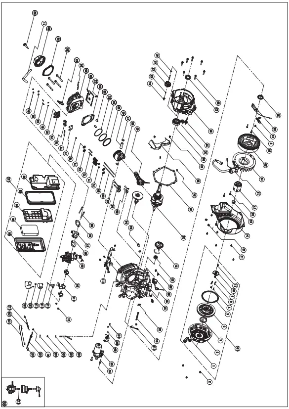
| No. | Alias | Description | Qty. |
| 1 | 21.061300.00 | Handle, Recoil, Soft | 1 |
| 2 | 1.5789.0608 | Flange Bolt M6 × 8 | 4 |
| 3 | 46.061100.00.2 | Cover, Recoil Starter, Black | 1 |
| 4 | 45.060005.00 | Spring, Recoil Starter | 1 |
| 5 | 45.061102.00 | Reel, Recoil Starter | 1 |
| 6 | 2.10.003 | Rope Ø5 × 1550 | 1 |
| 7 | 45.060003.00 | Spring, Ratchet | 2 |
| 8 | 45.060002.00 | Starter Ratchet, Steel | 2 |
| 9 | 45.060009.00 | Spring, Ratchet Guide | 1 |
| 10 | 45.060007.00 | Ratchet Guide | 1 |
| 11 | 45.060008.00 | Screw, Ratchet Guide | 1 |
| 12 | 1.5789.0612 | Flange Bolt M6 × 12 | 12 |
| 13 | 2.05.005 | Clamp Ø6 | 2 |
| 14 | 46.080100.01.48 | Fan Cover, Yellow | 1 |
| 15 | 2.02.007 | Nut M16 × 1.5 | 1 |
| 16 | 1.5789.0629 | Flange Bolt M6 × 29 | 4 |
| 17 | 45.060001.00 | Pulley, Starter | 1 |
| 18 | 46.123000.03 | Ignition Coil, Silicon Rubber | 1 |
| 19 | 45.080001.00 | Cooling Fan | 1 |
| 20 | 46.120100.04 | Flywheel | 1 |
| 21 | 45.030006.00 | Plate, Coil | 1 |
| 22 | 45.121000.00 | Coil, Charging | 1 |
| 23 | 2.11.007 | Oil Seal Ø35 × Ø52 × 8 | 2 |
| 24 | 2.05.050 | Wire Clip, 100 mm | 1 |
| 25 | 45.030032.00 | Sheath, Wire | 1 |
| 26 | 2.03.023 | Washer Ø12.5 × Ø20 × 2, Drain Bolt | 2 |
| 27 | 46.030100.01 | Crankcase | 1 |
| 28 | 45.127000.02 | Oil Level Sensor | 1 |
| 29 | 1.5789.0615 | Flange Bolt M6 × 15 | 2 |
| 30 | 1.276.6202 | Bearing 6202 | 2 |
| 31 | 47.050006.00 | Weight Balancer | 1 |
| 32 | 45.050100.14 | Crankshaft | 1 |
| 33 | 46.030008.00 | Gasket, Crankcase Cover | 1 |
| 34 | 2.04.001 | Dowel Pin Ø9 × 14 | 2 |
| 35 | 46.080600.00 | Air Guide, Right Side | 1 |
| 36 | 1.276.6207 | Bearing 6207 | 1 |
| 37 | 46.031000.01.48 | Oil Dipstick Assembly, Yellow | 1 |
| 38 39 | 45.030007.00 1.5789.0840.0.8 | Cover, Crankcase Flange Bolt M8 × 40 | 1 7 |
| 40 | 2.03.021.1 | Washer Ø6.4 × Ø13 × 1, Black | 1 |
| 41 | 45.110013.00 | Shaft, Governor Gear | 1 |
| 42 | 45.110100.00 | Gear, Governor | 1 |
| 43 | 21.110011.00 | Clip, Governor Gear | 1 |
| 44 | 45.110012.00 | Bushing, Governor Gear | 1 |
| 45 | 47.050200.00 | Connecting Rod | 1 |
| 46 | 46.050005.00 | Piston | 1 |
| 47 | 2.09.004 | Circlip Ø21 × Ø1 | 2 |
| 48 | 45.050003.00 | Pin, Piston | 1 |
| 49 | 45.050303.00 | Ring, Oil | 1 |
| 50 | 46.050302.00 | Ring, Second Piston | 1 |
| 51 | 46.050301.00 | Ring, First Piston | 1 |
| 52 | 2.04.004 | Dowel Pin Ø12 × 20 | 2 |
| 53 | 46.030009.01 | Gasket, Cylinder Head | 1 |
| 54 | 46. 80400. 0 | Air Guide, Lower | 1 |
| 55 | 46.010100.00 | Cylinder Head | 1 |
| 56 | 2.01.010 | Stud Bolt M8 × 35 | 2 |
| 57 | 2.15.001(F6TC) | Spark Plug F6TC | 1 |
| 58 | 2.08.014 | Flange Bolt M10 × 80 | 4 |
| 59 | 46.020002.00 | Gasket, Cylinder Head Cover | 1 |
| 60 | 46.021000.00 | Cover, Cylinder Head | 1 |
| 61 | 45.020001.02 | Breather Tube | 1 |
| No. | Alias | Description | Qty. |
| 62 | 45.020100.00 | Bolt, Cylinder Head Cover | 1 |
| 63 | 2.08.039 | Drain Bolt M10 × 1.25 × 25 | 2 |
| 64 | 46.041000.00 | Camshaft | 1 |
| 65 | 45.040013.00 | Lifter, Valve | 2 |
| 66 | 45.040002.00 | Valve, Intake | 1 |
| 67 | 45.040006.00 | Valve, Exhaust | 1 |
| 68 | 46.040005.00 | Push Rod | 2 |
| 69 | 45.040015.00 | Retainer, Valve Spring Down | 2 |
| 70 | 45.040017.00 | Oil Seal, Valve | 2 |
| 71 | 45.040003.00 | Spring, Valve | 2 |
| 72 | 23.040010.00 | Bolt, Rocker Arm | 2 |
| 73 | 45.040001.00 | Retainer, Intake Valve Spring | 1 |
| 74 | 45.040007.00 | Retainer, Exhaust Valve Spring | 1 |
| 75 | 45.040008.00 | Rotator, Exhaust Valve | 1 |
| 76 | 46.040004.00 | Guide Plate, Push Rod | 1 |
| 77 | 46.040016.00 | Shaft, Rocker Arm | 1 |
| 78 | 46.040201.00 | Retainer, Rocker Arm | 1 |
| 79 | 46.040009.00 | Rocker Arm, Intake Valve | 1 |
| 80 | 46.040018.00 | Rocker Arm, Exhaust Valve | 1 |
| 81 | 1.97.1.06 | Washer Ø6 | 2 |
| 82 | 22.040012.00 | Screw, Valve Adjustment | 2 |
| 83 | 1.6177.1.06 | Flange Nut M6 | 2 |
| 84 | 21.040021.00 | Nut M6 × 0.5, Lock | 2 |
| 85 | 2.01.008 | Stud Bolt M6 × M8 × 105 | 2 |
| 86 | 46.130002.20 | Gasket, Insulator | 1 |
| 87 | 45.130001.00 | Insulator, Carburetor | 1 |
| 88 | 46.130003.20 | Gasket, Carburetor | 1 |
| 89 | 46.131000.22 | Carburetor | 1 |
| 90 | 46.130004.20 | Gasket, Air Cleaner | 2 |
| 91 | 1.6177.06 | Flange Nut M6 | 3 |
| 92 | 46.091100.04 | Base, Air Cleaner | 1 |
| 93 | 45.091002.20 | Seal, Air Cleaner | 1 |
| 94 | 45.091001.20 | Separator, Air Cleaner | 1 |
| 95 | 45.091003.20 | Element, Air Cleaner | 1 |
| 96 | 46.091200.04 | Cover, Air Cleaner | 1 |
| 97 | 1.5789.0835 | Flange Bolt M8 × 35 | 2 |
| 98 | 45.125100.00 | Starter Motor Assembly | 1 |
| 99 | 45.125200.01 | Relay, Starter, Remote Control | 1 |
| 100 | 1.93.05 | Lock Washer Ø5 | 2 |
| 101 | 1.16674.0516 | Flange Bolt M5 × 16 | 2 |
| 102 | 45.110001.00 | Shaft, Governor Arm | 1 |
| 103 | 2.03.019 | Washer Ø8.2 × Ø17 × 0.8 | 1 |
| 104 | 2.11.006 | Oil Seal Ø7 × Ø14 × 5 | 1 |
| 105 | 45.110008.00 | Pin, Shaft | 1 |
| 106 | 45.110003.00 | Arm, Governor | 1 |
| 107 | 2.08.040 | Bolt M6 × 21, Governor Arm | 1 |
| 108 | 45.110006.00 | Rod, Governor | 1 |
| 109 | 45.110005.00 | Spring, Throttle Return | 1 |
| 110 | 45.110007.00 | Spring, Governor | 1 |
| 111 | 46.080300.20 | Air Guide, Upper | 1 |
| 112 | 46.131017.20 | Main Jet, Standard | 1 |
| 113 | 46.091000.04 | Air Cleaner Assembly | 1 |
| 114 | 46.061000.00 | Recoil Assembly | 1 |
| 115 | 21. 20400. 0 | Diode Assembly | 1 |
| 116 | 45.130005.01 | Support, Stepper Motor | 1 |
| 117 | 26.130015.24 | Connecter, Choke Valve Axis | 1 |
| 118 | 81.130010.00 | Spring, Connecter | 1 |
| 119 | 45.132200.01 | Stepper Motor | 1 |
| 120 | 1.823.0408 | Screw M4 × 8 | 2 |
| 121 | 81.132001.00 | Cover, Stepper Motor | 1 |
CPG9000 E2 (EU/SC) PARTS DIAGRAM
| No. | Part Number | Description | Qty |
| 1 | 21.061300.00 | Handle, Recoil, Soft | 1 |
| 2 | 1.5789.0608 | Flange Bolt M6 × 8 | 4 |
| 3 | 46.061100.00.2 | Cover, Recoil Starter, Black | 1 |
| 4 | 45.060005.00 | Spring, Recoil Starter | 1 |
| 5 | 45.061102.00 | Reel, Recoil Starter | 1 |
| 6 | 2.10.003 | Rope Ø5 × 1550 | 1 |
| 7 | 45.060003.00 | Spring, Ratchet | 2 |
| 8 | 45.060002.00 | Starter Ratchet, Steel | 2 |
| 9 | 45.060009.00 | Spring, Ratchet Guide | 1 |
| 10 | 45.060007.00 | Ratchet Guide | 1 |
| 11 | 45.060008.00 | Screw, Ratchet Guide | 1 |
| 12 | 1.5789.0612 | Flange Bolt M6 × 12 | 12 |
| 13 | 2.05.001 | Clamp Ø8 × 6.5 | 2 |
| 14 | 47.080100.01.48 | Fan Cover, Yellow | 1 |
| 15 | 2.02.007 | Nut M16 × 1.5 | 1 |
| 16 | 1.5789.0629 | Flange Bolt M6 × 29 | 4 |
| 17 | 45.060001.00 | Pulley, Starter | 1 |
| 18 | 46.123000.03 | Ignition Coil, Silicon Rubber | 1 |
| 19 | 48.080001.00 | Cooling Fan | 1 |
| 20 | 46.120100.04 | Flywheel | 1 |
| 21 | 45.030006.00 | Plate, Coil | 1 |
| 22 | 45.121000.00 | Coil, Charging | 1 |
| 23 | 2.11.007 | Oil Seal Ø35 × Ø52 × 8 | 2 |
| 24 | 2.05.050 | Wire Clip 100 mm | 1 |
| 25 | 152.070031.01 | Sheath, Wire | 1 |
| 26 | 2.03.023 | Washer Ø12.5 × Ø20 × 2, Drain Bolt | 1 |
| 27 | 48.030100.00 | Crankcase | 1 |
| 28 | 45.127000.02 | Oil Level Sensor | 1 |
| 29 | 1.5789.0615 | Flange Bolt M6 × 15 | 2 |
| 30 | 1.276.6202 | Bearing 6202 | 2 |
| 31 | 48.050006.00 | Weight Balancer | 1 |
| 32 | 47.050100.01 | Crankshaft | 1 |
| 33 | 46.030008.00 | Gasket, Crankcase Cover | 1 |
| 34 | 2.04.001 | Dowel Pin Ø9 × 14 | 2 |
| 35 | 46.080600.00 | Air Guide, Right Side | 1 |
| 36 | 1.276.6207 | Bearing 6207 | 1 |
| 37 | 46.031000.01.48 | Oil Dipstick Assembly, Yellow | 1 |
| 38 39 | 45.030007.00 1.5789.0840.0.8 | Cover, Crankcase Flange Bolt M8 × 40 | 1 7 |
| 40 | 2.03.021.1 | Washer Ø6.4 × Ø13 × 1, Black | 1 |
| 41 | 45.110013.00 | Shaft, Governor Gear | 1 |
| 42 | 45.110100.00 | Gear, Governor | 1 |
| 43 | 21.110011.00 | Clip, Governor Gear | 1 |
| 44 | 45.110012.00 | Bushing, Governor Gear | 1 |
| 45 | 47.050200.00 | Connecting Rod | 1 |
| 46 | 48.050005.00 | Piston | 1 |
| 47 | 2.09.004 | Circlip Ø21 × Ø1 | 2 |
| 48 | 45.050003.00 | Pin, Piston | 1 |
| 49 | 48.050303.00 | Ring, Oil | 1 |
| 50 | 48.050302.00 | Ring, Second Piston | 1 |
| 51 | 48.050301.00 | Ring, First Piston | 1 |
| 52 | 2.04.004 | Dowel Pin Ø12 × 20 | 2 |
| 53 | 48.030009.00 | Gasket, Cylinder Head | 1 |
| 54 | 46. 80400. 0 | Air Guide, Lower | 1 |
| 55 | 47.010100.01 | Cylinder Head | 1 |
| 56 | 2.01.010 | Stud Bolt M8 × 35 | 2 |
| 57 | 2.15.001(F6TC) | Spark Plug F6TC | 1 |
| 58 | 2.08.122 | Flange Bolt M10 × 95 | 4 |
| 59 | 46.020002.00 | Gasket, Cylinder Head Cover | 1 |
| 60 | 47.021000.00 | Cover, Cylinder Head | 1 |
| 61 | 45.020001.02 | Breather Tube | 1 |
| No. | Part Number | Description | Qty |
| 62 | 47.020100.00 | Bolt, Cylinder Head Cover | 1 |
| 63 | 81.132001.00 | Cover, Stepper Motor | 1 |
| 64 | 48.041000.00 | Camshaft | 1 |
| 65 | 48.040013.00 | Lifter, Valve | 2 |
| 66 | 47.040002.00 | Valve, Intake | 1 |
| 67 | 47.040006.00 | Valve, Exhaust | 1 |
| 68 | 46.040005.00 | Push Rod | 2 |
| 69 | 45.040015.00 | Retainer, Valve Spring | 2 |
| 70 | 45.040017.00 | Oil Seal, Valve | 2 |
| 71 | 45.040003.00 | Spring, Valve | 2 |
| 72 | 23.040010.00 | Bolt, Rocker Arm | 2 |
| 73 | 45.040001.00 | Retainer, Intake Valve Spring | 1 |
| 74 | 45.040007.00 | Retainer, Exhaust Valve Spring | 1 |
| 75 | 45.040008.00 | Rotator, Exhaust Valve | 1 |
| 76 | 46.040004.00 | Guide Plate, Push Rod | 1 |
| 77 | 46.040016.00 | Shaft, Rocker Arm | 1 |
| 78 | 46.040201.00 | Retainer, Rocker Arm | 1 |
| 79 | 46.040009.00 | Rocker Arm, Intake Valve | 1 |
| 80 | 46.040018.00 | Rocker Arm, Exhaust Valve | 1 |
| 81 | 1.97.1.06 | Washer Ø6 | 2 |
| 82 | 22.040012.00 | Screw, Valve Adjustment | 2 |
| 83 | 1.6177.1.06 | Flange Nut M6 | 2 |
| 84 | 21.040021.00 | Nut M6 × 0.5, Lock | 2 |
| 85 | 2.01.008 | Stud Bolt M6 × M8 × 105 | 2 |
| 86 | 46.130002.20 | Gasket, Insulator | 1 |
| 87 | 45.130001.00 | Insulator, Carburetor | 1 |
| 88 | 46.130003.20 | Gasket, Carburetor | 1 |
| 89 | 48.131000.11 | Carburetor | 1 |
| 90 | 46.130004.20 | Gasket, Air Cleaner | 2 |
| 91 | 1.6177.06 | Flange Nut M6 | 3 |
| 92 | 46.091100.04 | Base, Air Cleaner | 1 |
| 93 | 45.091002.20 | Seal, Air Cleaner | 1 |
| 94 | 45.091001.20 | Separator, Air Cleaner | 1 |
| 95 | 45.091003.20 | Element, Air Cleaner | 1 |
| 96 | 46.091200.04 | Cover, Air Cleaner | 1 |
| 97 | 1.5789.0835 | Flange Bolt M8 × 35 | 2 |
| 98 | 48.125100.00 | Starter Motor Assembly | 1 |
| 99 | 45.125200.01 | Relay, Starter, Remote Control | 1 |
| 100 | 1.93.05 | Lock Washer Ø5 | 2 |
| 101 | 1.16674.0516 | Flange Bolt M5 × 16 | 2 |
| 102 | 45.110001.00 | Shaft, Governor Arm | 1 |
| 103 | 2.03.019 | Washer Ø8.2 × Ø17 × 0.8 | 1 |
| 104 | 2.11.006 | Oil Seal Ø7 × Ø14 × 5 | 1 |
| 105 | 45.110008.00 | Pin, Shaft | 1 |
| 106 | 45.110003.01 | Arm, Governor | 1 |
| 107 | 2.08.040 | Bolt M6 × 21, Governor Arm | 1 |
| 108 | 45.110006.00 | Rod, Governor | 1 |
| 109 | 45.110005.00 | Spring, Throttle Return | 1 |
| 110 | 45.110007.00 | Spring, Governor | 1 |
| 111 | 46.080300.20 | Air Guide, Upper | 1 |
| 112 | 48.131017.01 | Main Jet, Standard | 1 |
| 48.131017.01.01 | Main Jet, Altitude | / | |
| 113 | 46.091000.04 | Air Cleaner Assembly | 1 |
| 114 | 46. 61000. 0 | Recoil Assembly | 1 |
| 115 | 21.120400.00 | Diode Assembly | 1 |
| 116 | 2.08.039 | Drain Bolt M10 × 1.25 × 25 | 1 |
| 117 | 1.823.0408 | Screw M4 × 8 | 2 |
| 118 | 45.130005.01 | Support, Stepper Motor | 1 |
| 119 | 26.130015.24 | Connecter, Choke Valve Axis | 1 |
| 120 | 81.130010.00 | Spring, Connecter | 1 |
| 121 | 45.132200.01 | Stepper Motor | 1 |
CPG9000 E2 (EU/SC) PARTS DIAGRAM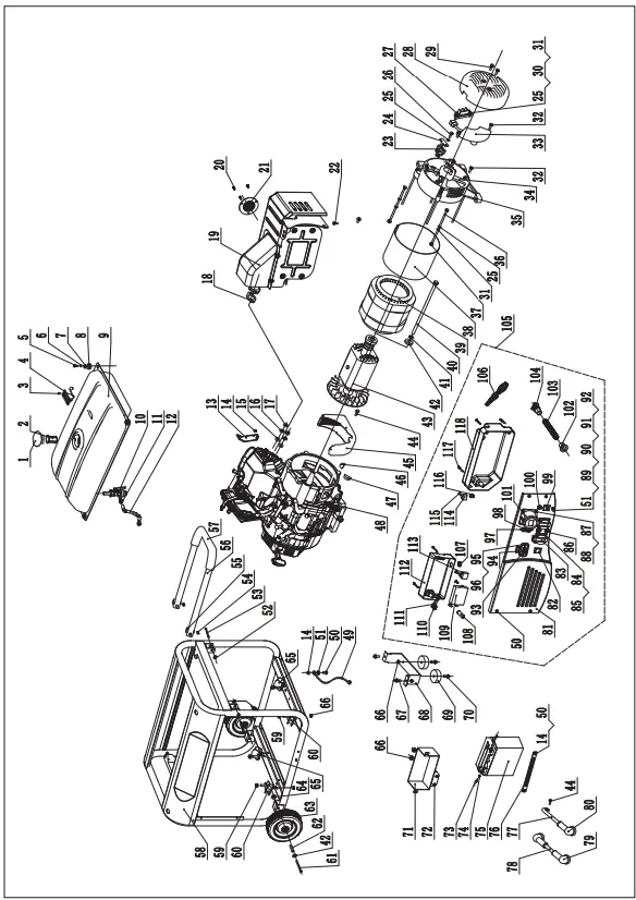
| No | Part Number | Destription | QTY |
| 1 | 122.070100.03 | Fuel Tank Cap | 1 |
| 2 | 122.070300.02 | Fuel Filter | 1 |
| 3 | 1.819.0510 | Screw M5 x 10 | 2 |
| 4 | 152.072000.03 | Fuel Meter Assembly | 1 |
| 5 | 1.5789.0620.2 | Flange Bolt M6 x 20 | 4 |
| 6 | 1.93.06 | Spring Washer ĭ 6 | 4 |
| 7 | 2.03.004 | Washer ĭ 6 | 4 |
| 8 | 122.070015.01 | Mount Vibration, Fuel Tank | 4 |
| 9 | 152.071000.03.48 | Fuel Tank | 1 |
| 10 | 122.070400.03 | Fuel Cock | 1 |
| 11 | 2.06.007 | Clamp | 2 |
| 12 | 152.070011.06 | Pipe,Fuel ( 6.7 in ) | 1 |
| 13 | 45.090006.20 | Holder, Air Cleaner | 1 |
| 14 | 1.6177.1.06 | Nut M 6 | 4 |
| 15 | 1.848.08 | Washer ĭ 8 | 2 |
| 16 | 1.93.08 | Spring Washer ĭ 8 | 2 |
| 17 | 1.6175.08 | Nut M8 | 2 |
| 18 | 46.100001.07 | Muffler Gasket | 1 |
| 19 | 46.101000.01.2 | Muffler Assembly | 1 |
| 20 | 1.9074.4.0510 | Bolt And Washer Assembly M5 x 10 | 3 |
| 21 | 46.101300.00 | Arrester Assembly, Spark | 1 |
| 22 | 1.16674.0825 | Flange Bolt M8x25 | 2 |
| 23 | 152.190300.00 | Carbon Bursh Assembly | 1 |
| 24 | 122.190004.01 | Pinch | 1 |
| 25 | 1.93.05 | Spring Washer ĭ 5 | 5 |
| 26 | 1.5783.0520 | Bolt M5 x 20 | 1 |
| 27 | 122.190400.00 | Terminal Block | 1 |
| 28 | 152.190003.00.48 | Generator End Cover | 1 |
| 29 | 1.16674.0512.2 | Flange Bolt M5 x 12 | 2 |
| 30 | 1.5783.0516 | Bolt M5 x 16 | 2 |
| 31 | 1.97.1.05 | Washer ĭ 5 | 4 |
| 32 | 1.16674.0516 | Flange Bolt M5 x 16 | 3 |
| 33 | 154.190200.02 | AVR | 1 |
| 34 | 152.190002.00 | End Housing | 1 |
| 35 | 2.08.069 | Flange Bolt M6 x 194 | 4 |
| 36 | 2.08.071 | Bolt M5 x 229 | 2 |
| 37 | 1.6175.05 | Nut M5 | 2 |
| 38 | 154.191002.00 | Stator Cover | 1 |
| 39 | 154.191200.01 | Stator Assembly | 1 |
| 40 | 2.08.070 | Flange Bolt M10 x 280 | 1 |
| 41 | 1.7244.10 | Spring Washer ĭ 10 | 1 |
| 42 | 1.96.10 | Washer ĭ 10 | 3 |
| 43 | 154.191100.00 | Rotor Assembly | 1 |
| 44 | 1.5789.0608 | Flange Bolt M6 x 8 | 3 |
| 45 | 152.192300.00 | Air Guide | 1 |
| 46 | 152.190005.00 | Rubber, Fore-Cover | 1 |
| 47 | 152.190005.01 | Rubber, Fore-Cover | 1 |
| 48 | CPG9000E2-EU | Engine | 1 |
| 49 | 5.1900.026 | Grounding Line | 1 |
| 50 | 1.5789.0612 | Flange Bolt M6 x 12 | 7 |
| 51 | 1.862.06 | Lock Washer ĭ 6 | 2 |
| 52 | 1.894.1.10 | Circlip ĭ 10 | 2 |
| 53 | 152.200703.04 | Pin,Handle | 2 |
| 54 | 1.894.1.08 | Circlip ĭ8 | 2 |
| 55 | 152.200703.02 | Pin, Handle | 2 |
| 56 | 152.200701.02.2 | Handle | 1 |
| 57 | 152.200702.02 | Cover, Handle | 1 |
| 58 | 65264.0.10.2 | Frame | 1 |
| 59 | 1.6177.1.10 | Nut M10 | 4 |
| No | Part Number | Destription | QTY |
| 60 | 152.201200.01 | Motor Mount | 2 |
| 61 | 1.5182.10120 | Bolt M10 x 120 | 2 |
| 62 | 253.200016.00 | Bush ĭ 16 x ĭ 10.5 x 69.5 | 2 |
| 63 | 152.201701.04.48 | 10 in Wheel | 2 |
| 64 | 1.6182.10 | Nut M10 | 2 |
| 65 | 152.201200.02 | Motor Mount | 2 |
| 66 | 1.6177.1.08 | Nut M8 | 12 |
| 67 | 1.5789.0816 | Flange Bolt M8 x 16 | 2 |
| 68 | 152.200002.01.2 | Support Leg | 1 |
| 69 | 152.201400.00 | Rubber, Support | 2 |
| 70 | 1.5789.0825 | Flange Bolt M8 x 25 | 2 |
| 71 | 152.200901.06.2 | Battery Support | 1 |
| 72 | 1.16674.0835 | Flange Bolt M8 x 35 | 2 |
| 73 | 1.9074.3.0510 | Bolt And Washer Assembly M5 x 10 | 2 |
| 74 | 1.6177.1.05 | Nut M5 | 2 |
| 75 | 9.1000.150 | Battery 12V15 AH | 1 |
| 76 | 152.200902.01.2 | Pinch, Rubber | 1 |
| 77 | 5.1900.025 | Black Wire, Battery | 1 |
| 78 | 5.1900.024 | Red Wire, Battery | 1 |
| 79 | 152.200013.01.3 | Jacket, Red | 2 |
| 80 | 152.200013.01 | Jacket, Black | 1 |
| 81 | 152.159.049.2 | Control Panel | 1 |
| 82 | 5.1000.001.3 | Switch | 1 |
| 83 | 5.1120.013 | Receptacle | 2 |
| 84 | 1.819.0414.2 | Bolt and Washer Assembly M4 x 14 | 8 |
| 85 | 1.6177.1.04.2 | Nut M4 | 8 |
| 86 | 5.1210.920 | 20Amp Circuit Breaker, Push Button | 2 |
| 87 | 1.819.0516.2 | Bolt and Washer Assembly M5 x 16 | 4 |
| 88 | 1.6177.1.05.2 | Nut M5 | 4 |
| 89 | 1.5783.0622.3 | Bolt M6 x 22 | 1 |
| 90 | 1.6175.06.3 | Nut M6 | 2 |
| 91 | 1.93.06.3 | Spring Washer ĭ6 | 2 |
| 92 | 1.97.1.06.3 | Washer Ø6, Green | 2 |
| 93 | 5.1430.002 | Intelligauge | 1 |
| 94 | 5.1000.000.3 | Switch | 1 |
| 95 | 1.9074.4.0414.2 | Screw And Washer Assembly M4 x 14 | 2 |
| 96 | 1.6177.1.04.2 | Flange Lock Nut M4 | 2 |
| 97 | 1.9074.4.0306.2 | Bolt M3 x 6 | 2 |
| 98 | 5.1230.304 | 30.4Amp Circuit Breaker | 1 |
| 99 | 5.1110.001 | Receptacle | 1 |
| 100 | 5.1200.110.1 | Breaker | 1 |
| 101 | 5.1120.014 | Receptacle | 1 |
| 102 | 122.210003.01 | Plug | 1 |
| 103 | 5.1330.007 | Sheath, Wire | 1 |
| 104 | 152.210003.02 | Plug | 1 |
| 105 | CPG9000E2-EU.21 | Control Panel Assembly | 1 |
| 106 | CPG9000E2-EU.21.10 | Wire Assembly | 1 |
| 107 | 122.210003.00 | Plug | 1 |
| 108 | 5.1280.003 | Fuse(10A) | 1 |
| 109 | 5.1830.001 | Remote Control Module | 1 |
| 110 | 5.1040.004 | Switch | 1 |
| 111 | 5.1460.003 | Indicator light | 1 |
| 112 | 152.210002.11 | Control Box | 1 |
| 113 | 5.1820.000 | Charger | 1 |
| 114 | 5.1800.000 | Rectifier | 1 |
| 115 | 1.823.0514.2 | Screw M5 x 14 | 4 |
| 116 | 122.210003.00 | Plug | 1 |
| 117 | 1.9074.1.0538.2 | Bolt and Washer Assembly M5 x 38 | 5 |
| 118 | 152.210002.09 | Control Box | 1 |