![]()
AV-20 / AV-20-S
Installation Manual
UAV-1003613-001
Rev D
Legal Notices
© 2019 – 2020 uAvionix Corporation. All rights reserved.
Except as expressly provided herein, no part of this guide may be reproduced, transmitted, disseminated, downloaded, or stored in any storage medium, for any purpose without the express written permission of uAvionix. uAvionix grants permissions to download a single copy of this guide onto an electronic storage medium to be viewed for personal use provided that the complete text of this copyright notice is retained. The unauthorized commercial distribution of this manual or any revision hereto is strictly prohibited.
uAvionix ® and Ping ® are registered trademarks of uAvionix Corporation and may not be used without the express permission of uAvionix.
AV-20, AV-20-S, and AeroVonics are trademarks of uAvionix Corporation and may not be used without the express permission of uAvionix.
Patent uavionix.com/patents
Warnings/Disclaimers
uAvionix is not liable for damages arising from the use or misuse of this product.
This equipment is classified by the United States Department of Commerce’s Bureau of Industry and Security (BIS) as Export Control Classification Number (ECCN) 7A994.
These items are controlled by the U.S. Government and authorized for export only to the country of ultimate destination for use by the ultimate consignee or end-user(s) herein identified. They may not be resold, transferred, or otherwise disposed of, to any other country or to any person other than the authorized ultimate consignee or end-user(s), either in their original form or after being incorporated into other items, without first obtaining approval from the U.S. government or as otherwise authorized by U.S. law and regulations.
UAV-1003613-001
Rev D
Document Revisions
Revision | Date | Description of Change |
| A | 09/20/2017 | Initial Release as AeroVonics D-0011-0 |
| B | 10/03/2018 | Updated for initial NORSE certification, latest UI for Software Release 1.0. Updates from FAA Review. |
| C | 11/24/2019 | Release as uAvionix UAV-1003613-001 with updated device part numbers |
| D | 11/18/2020 | Remove pressurized aircraft limitation. Add guidance for OAT installation and AV-20 mounting. Update mechanical drawing. |
System Description
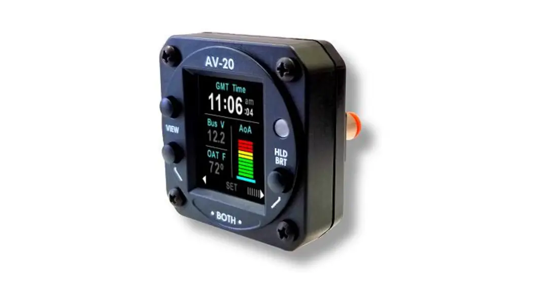
The uAvionix AV-20 and AV-20-S Multi-Function Displays provide a wide array of supplemental flight information.
Features Include:
- AoA Display (Voice Alerting & Peaks)
- G-Meter Display (Voice Alerting & Peaks)
- Attitude (Roll / Pitch)
- Slip / Skid
- Clock (GMT / Local)
- Outside Air Temperature (C / F)
- Bus Voltage Display
- Dual User Timers (Count Up / Down)
- Engine Run Timer
- Flight Timer
- Density Altitude Display
- True Airspeed Display (Kts / Mph)
Internal Battery Operation
The unit incorporates a full-color sunlight-readable display, a bezel-mounted light sensor for automatic display brightness, and an internal battery for operation in the event of power loss. The unit is designed to fit a standard 2¼” mounting hole and is approximately 2 inches deep. Dual ¼” quick-connect fittings are provided for pitot and static connections on the rear of the unit.
A pre-wired wire harness is also available to simplify installation.
![]() The AV-20-S model incorporates internal inertial sensors (gyroscopes and accelerometers), and precision pressure sensors (pitot and static). This allows expanded functionality over the base AV-20 model.
The AV-20-S model incorporates internal inertial sensors (gyroscopes and accelerometers), and precision pressure sensors (pitot and static). This allows expanded functionality over the base AV-20 model.
See the detailed functionality matrix to determine which features are available in each model.
![]() Unless explicitly noted, references in this manual to the AV-20 are applicable to both configurations.
Unless explicitly noted, references in this manual to the AV-20 are applicable to both configurations.
Model Variants & Required Interfaces
The AV-20 is available in two configurations:
- AV-20 (Part Number UAV-1003591-001 or U-1001-0): The base model does not include internal inertial sensors or pitot-static sensors. Functions are limited to those indicated below.
- AV-20-S (Part Number UAV-1003310-001 or U-1002-0): The enhanced (S)sensor model includes the base model functions plus the inertial sensors and pitot-static sensors. Full functionality is available in this configuration.
Feature / Model | AV-20 | AV-20-S | Related Interfaces |
| Clock | √ | √ | |
| OAT | √ | √ | OAT Probe (1) |
| Bus Voltage | √ | √ | |
| Dual User Timers | √ | √ | |
| Engine Run Timer | √ | √ | |
| Flight Timer | χ | √ | Pitot and Static Required |
| APA | χ | √ | Pitot and Static Required |
| Attitude | χ | √ | Pitot and Static Required |
| Density Alt | χ | √ | Pitot and Static Required OAT Probe (1) |
| True Airspeed | χ | √ | Pitot and Static Required OAT Probe (1) |
| Slip / Skid | χ | √ | |
| G-Meter | χ | √ | |
| Battery Operation | χ | √ | |
| Audio Alerts | |||
| Timer Alert | √ | √ | Audio Panel Connection (2) |
| AoA Alert | χ | √ | Audio Panel Connection (2) |
| G Limit Alert | χ | √ | Audio Panel Connection (2) |
| Notes: (1) The OAT probe is optional. The unit will automatically detect the presence of the sensor and enable functionality related to its use. (2) The audio panel connection is optional. Visual alerts will be functional in all modes of operation. | |||
Table 1 – Functional Dependencies
![]() The model and part number are shown on the splash screen on power-up, and on the system setup info page.
The model and part number are shown on the splash screen on power-up, and on the system setup info page.![]() Note that the base AV-20 incorporates both pitot and static ports on the rear of the unit but is not utilized. This is provided for upgrade purposes and is plugged from the factory. Do not remove the plugs.
Note that the base AV-20 incorporates both pitot and static ports on the rear of the unit but is not utilized. This is provided for upgrade purposes and is plugged from the factory. Do not remove the plugs. Do not connect Pitot and Static in the AV-20 Base model units. Pitot and Static connections ARE required in the AV-20-S Model for proper functionality.
Equipment Connections
All connections are provided on the single 9-Pin D-sub connector and the two pneumatic fittings.
The unit connects to aircraft power via a normal power circuit with a dedicated 1 Amp breaker.
Outside Air Temp Input
The outside air temperature interface requires an external analog probe. This port connection is compatible with the Davtron probe analog probe P/N C307PS (not supplied). This is a simple two-wire current source based on the Analog Devices AD590KH component.
The sensor reading may be trimmed in the setup pages.
Do not tap into an existing OAT system that is in use (the probes may not be put in parallel or series).OAT functionality requires separate approval for the installation of the OAT probe.
Audio Output
The audio panel connection is a low-voltage analog output that is designed to connect directly to an audio panel (typically a non-switched input). High power outputs capable of directly driving a cockpit speaker are not provided.
Manufacturing Port
A dedicated RS-232 bi-directional serial port is provided for manufacturing test and calibration purposes. These lines are not connected in the aircraft installation. Two spare RS-232 connections are also not connected.
Pitot and Static Inputs
Internal pressure sensors measure both pitot and static pressure and are required for air data base functionality, including AOA and Attitude. Industry-standard ¼” quick connect fittings are utilized. Reference the wiring diagram for details on how to release the tubing from the fitting.
Certification Basis
The AV-20 and AV-20-S are both FAA-approved designs, are suitable for certificated aircraft, and are FAA approved under NORSE policy PS-AIR-21.8-1602. The AV-20-S complies with ASTM F3011 Standard Specification for Performance of
The angle of the Attack System.
The AV-20 and AV-20-S are supplemental systems and may not be used as a substitution for any required certificated aircraft system. No operational credit may be taken for the installation of the system.The AV-20 and AV-20-S are limited to installation in Part 23, Class I and II aircraft. Installation in other categories of aircraft may require additional certification activities.Installations requiring penetration of a pressurized aircraft’s pressure vessel may require additional certification activities or FAA-approved data.
Operating Limits
The following operational limitations are applicable:
| Operating Limits | |
| The angle of Attack Range | 0° to +30° |
| The angle of Attack Resolution | 1° |
| The angle of Attack Operation | +35 to +300 Knots |
| The angle of Attack Accuracy | 2.5° |
| Density Alt Range (Accuracy) | -1,000 to +25,000 Feet (± 500ft) |
| TAS Range (Accuracy) | +35 to +300 Knots (± 20 kts) |
| Attitude Angle | No Limits |
| Attitude Rate Limit | ±250 Degrees / Second |
| Attitude Accuracy | 1° Static, 2.5° Dynamic |
| G Alert Limits | ± 8 g |
| OAT Range | -40°C to +70°C |
| OAT Accuracy | ±4°C |
| Slip Range (Accuracy) | ±7° (±2°) |
| Bus Voltage Range | 7 to 35 Volts |
| Bus Voltage Accuracy | ±1.0 Volt |
| Clock Accuracy | ± 1 Second/Day |
| Timer Accuracy | ± 1 Second/Hour |
Table 2 – Operating Limits
System Specifications
| Electrical Attributes | |
| Input Voltage Nominal | +10 to +32 VDC |
| Input Voltage Max | +60 VDC |
| Input Power Nominal | 3 Watts (0.25Amps @ 12VDC) |
| Input Power Max | 6 Watts (0.50 Amps @ 12VDC) |
| Required Circuit Breaker | 1 Amp |
| Operation on Battery (AV-20-S) | 30 Minutes (Standard 15°C Env) |
| Physical Attributes | |
| Mounting Configuration | 2 ¼” Round Instrument Hole |
| Dimensions wo/Connector | 2.4 x 2.4 x 1.2 Inches |
| Weight | 0.25 Lbs. |
| Electrical Connector | 9 Pin Male D-Sub |
| Pneumatic Connectors | ¼” OD Quick Connect |
| Mounting | (4X) #6-32 Machine Screws |
| Case Material | High Impact ABS Plastic |
| Environmental | |
| Operating Temp | -20°C to +55°C |
| Storage Temp (48 Hrs) | -30°C to +80°C (Via Analysis) |
| Humidity (48 Hrs) | 90% RH (Via Analysis) |
| Optical Characteristics | |
| Diagonal Size | 1.8” |
| Resolution | 128 x 160 |
| Contrast Ratio (Typical) | 500 |
| Brightness (Typical) | 1000 cd/m2 |
| Viewing Angle Left/Right | 60° |
| Viewing Angle Up | 45° |
| Viewing Angle Down | 10° |
| Backlight Lifetime (Typical) | 50,000 Hrs |
Table 3 – System Specifications
Intended Function
Reference the “AV-20 Pilot’s Guide” UAV-1003614-001 Section 2 for intended functionality.
Installation
Overview
The installation consists of the following steps:
- Remove/relocate any old instrumentation
- Add or locate an appropriate power source/breaker
- Wire power and interfaces as needed
- Mount the unit to the instrument panel with supplied screws
- Apply power and perform setup
![]() Proper mounting orientation is important to ensure the performance of the AV-20. Confirm the unit is oriented level in the roll-axis when installed in the panel.
Proper mounting orientation is important to ensure the performance of the AV-20. Confirm the unit is oriented level in the roll-axis when installed in the panel.
Mechanical Drawing
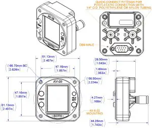
Figure 1 – Mechanical Drawing
Wiring Diagram
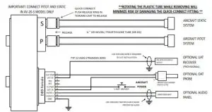
Figure 2 – Wiring Diagram
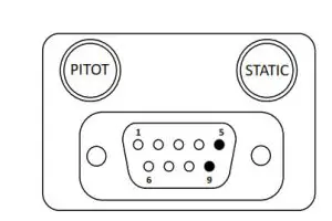
Figure 3 – Unit Connections – DB-9, Male Connector – Rear View
All connections are provided on the single 9-Pin D-sub connector and the two pneumatic fittings.
| Pin | Function | Type | Comment |
| 1 | OAT Supply | Output | OAT Sensor Supply Line |
| 2 | Serial Input | Input | UAT Display for Traffic (Provisional) |
| 3 | AV-XPORT Input | Input | Reserved |
| 4 | AV-XPORT Output | Output | Reserved |
| 5 | Power | Power | +12 to +28 VDC |
| 6 | OAT Sensor | Input | OAT Sensor Input |
| 7 | Audio H | Output | Altitude Alerts / Other |
| 8 | Audio L | Output | To Audio Panel Ground |
| 9 | Ground | Power | To Aircraft Ground |
Table 4 – Connector Pinout
Setup
Refer to “AV-20 Pilot’s Guide” UAV-1003614-001 for detailed setup options and procedures. All options are available to the pilot to configure as desired. A summons the options are as follows:
– Which pages are enabled
– Which voice alerts are provided
– Audio alert volume
– AoA alerting thresholds
– G-Limit alerting thresholds
– Miscellaneous Settings
o Background color
o Temperature units
o Time format
o Speed units
o Screen Popup behavior
– OAT Trim
– Hard Calibration
Calibration & Limits
All calibration and limit settings are available to the pilot. These consist of:
- Upper and Lower AoA alerting Thresholds
- Upper and Lower G-Alerting Thresholds
- OAT Temperature Trim
- Hard Calibration
No installation-related calibration is required. See Instructions for Continued Airworthiness below for more information on Hard Calibration.
Instructions for Continued Maintenance & Operation
Limitations
- The AV-20 system may be used for supplemental information but may not replace any equipment required under 14 CFR 91.205.
- The AV-20 system is not a required system and may not be used as a substitution for the certificated aircraft system.
- No operational credit may be taken for the installation of the AV-20 system.
Internal Battery
The AV-20 incorporates a small Li-Po battery that may require replacement on an as-desired basis. It is suggested to return the unit to the manufacturer for battery replacement if any of the conditions are present:
AV-20 Models:
o The clock does not correctly maintain time while the aircraft is not operated.
AV-20-S Models:
o The on-battery operation time drops below 10 minutes when operated at nominal temperatures (10°C to 30°C).
o The clock does not correctly maintain time while the aircraft is not operated.
Hard Calibration
The AV-20-S utilizes internal inertial sensors for multiple purposes. These sensors can drift out of calibration over time. The setup menu provides for a Hard Calibration procedure that re-calibrates these sensors. Perform the Hard Calibration procedure if any of the following conditions are observed: AV-20 Models:
o Hard Calibration does not apply.
AV-20-S Modes:
o During power on, the AoA reference bar remains flashing (stabilizing state) for more than 2 minutes.
o During power on, the ALIGNING mode on the Attitude Indicator page remains for more than 2 minutes.
Note the Hard Calibration must be performed while not in flight, and with as little aircraft motion present.
The preferred location is inside a hanger with doors closed. The aircraft does not need to be leveled prior to calibration.
The Hard Calibration is not accessible while airspeed is above 40 kts.


