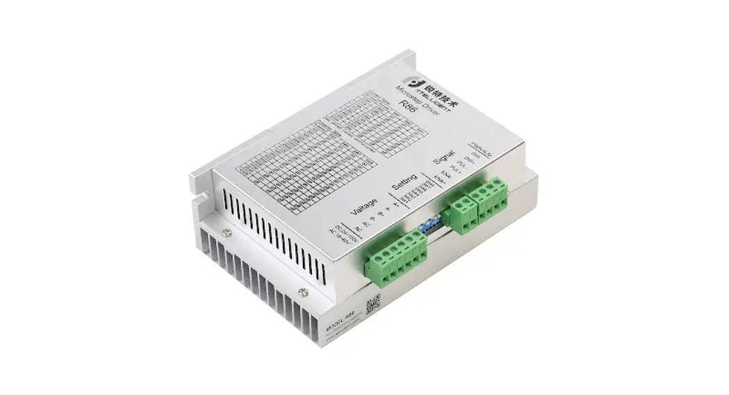
Digital Stepper Driver R86
User Manual
Shenzhen Intelligent Mechanical Electrical Technology Co.,ltd
Product overview
Thank you for choosing Rtelligent R series digital stepper driver.
R series stepper driver, which surpasses the performance of common analog stepper driver comprehensively based on the new 32-bit DSP platform developed by TI, and adopting the micro-stepping technology and PID current control algorithm design. The R series stepper drives have the features of low noise, low vibration, low heating, and high-speed high torque output, it is suitable for most stepper motors by integrated with the micro-stepping technology.
R86 driver can select the current and subdivision through the DIP switch. There are e16 subdivisions and 8 current selections. It has over-voltage, under-voltage, and over-current protection. Its input and output control signals are optically isolated.
| Power supply | 20 – 80 VAC / 24 — 100VDC |
| Output Current | Up to 7.2 amps ( peak value ) |
| Current control | PID current control algorithm |
| Micro-stepping settings | DIP switch settings, 16 options |
| Speed range | Use the suitable motor, up to 3000rpm |
| Resonance suppression | Automatically calculate the resonance point and inhibit the IF vibration |
| Parameter adaption | Automatically detect the motor parameter when Driver initialize, optimize the controlling performance |
| Pulse mode | Direction & pulse, CW/CCW double pulse |
| Pulse filtering | 2MHz digital signal processing filter |
| Neutral current | Automatically halve the current after the motor stops |
We hope that our products with excellent performance can help you to complete the sports control program successfully.
Please read this technical manual before using the products.
Application environment and installation
Environmental requirement
| Item | Intelligent R86 |
| Installation environment | Avoid dust, oil, and corrosive environment |
| Vibration | 0.5G(4.9m/s2) Max |
| Operating temperature/humidity | 0℃ ~ 45℃ / 90% RH or less (no condensation) |
| Storage and transportation temperature: | -10℃ ~ 70℃ |
| Cooling | Natural cooling / away from the heat source |
| Waterproof grade | IP54 |
Driver installation dimensions
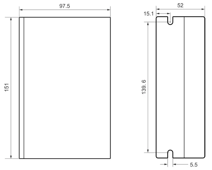
Driver installation requirements
Please install the driver vertically or horizontally, with its front-facing forward, top facing upward to facilitate cooling.
During assembly, avoid drillings and other foreign matters falling inside the driver.
During assembly, please use an M3 screw to fix it.
When there is a vibration source (such as a driller) close to the installation position, please use a vibrating absorber or a vibration-resistant rubber gasket.
When multiple drives are installed in the control cabinet, please pay attention to reserving enough space for sufficient heat dissipation. If necessary, you can configure cooling fans to ensure good heat dissipation conditions in the control cabinet.
Driver Port and Connection
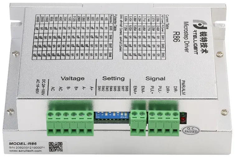
Port function description
| Function | Grade | Definition | Remarks |
| Power supply input port | AC | Input AC power supply | AC 20-80V DC 24-100V |
| AC | Input AC power supply | ||
| Motor connection port | B- | connect two terminals of the motor’s phase-B winding | |
| B+ | |||
| A- | connect two terminals of the motor’s phase-I winding | ||
| A+ | |||
| Enable connection | ENA+ | Enable control interface | 3.3 – 24V level compatible |
| ENA- | |||
| Pulse connection | PUL+ | Pulse input interface | |
| PUL- | |||
| DIR+ | Direction input interface | ||
| DIR- |
Power supply input
The power supply of the driver can be both AC power and DC power, and the input voltage range is 20V~80VAC or 24V~100VDC.
Please be minded that AC power cannot exceed 80VAC. and do not connect to commercial electricity(220VAC) directly!
The driver’s work mode is constant current control. The driver outputs the voltage to the motor by changing the input power into PWM chopping wave when it is working. In this case, the input power will affect the performance of the drive.
Power selection reference:
Voltage:
Stepper motor has the characteristics of torque decrease with the increase of motor speed, and the input voltage will affect the amplitude of high-speed torque reduction. Properly increasing the voltage of the input power supply can increase the output torque of the motor at high speed.
Stepper servo has a higher speed and torque output than ordinary stepper. Therefore, if you want to get better high-speed performance, you need to increase the power supply voltage of the driver.
Current:
The working process of the driver is to convert the input high-voltage and low-current power supply into the low-voltage and high-current at both ends of the motor winding. In actual use, the appropriate power supply should be selected according to the motor model, load torque and other factors.
The effects of regeneration voltage:
When the stepper motor is working, it also retains the characteristics of the generator.
When decelerating, the kinetic energy accumulated by the load will be converted into electrical energy and superimposed on the driver circuit and input power supply.
Pay attention to the setting of acceleration and deceleration time to protect the drive or power supply.
When the drive is powered off, you will see the drive’s LED indicator on when the load is pulled to make the motor move, which is also affected by this.
Motor connection
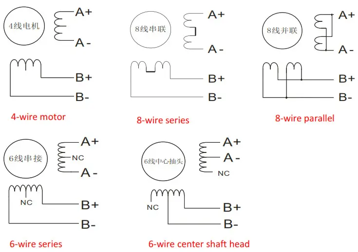
The matching motor of the R86 driver is the low resistance and low inductance hybrid stepper motor.
The common 2-phase stepper motor’s lead numbers are 4, 8, and 6.
There is only one connection mode for 4 lead motors.
Series and parallel connection mode are used by 8 leads motor:
When series used, the winding inductance increased. The set of Driver current should be about 0.7times than before. This is suitable for the low speed required.
When parallel used, the winding inductance decreased. The set of Driver current should be about 1.4times than before. This is suitable for the high speed required.
Parallel and central tapping connection modes are used by 6 leads motor:
When parallel used, all the winding connected, and the inductance was higher. This is suitable for the low speed required.
When central tapping was used, half of the winding connected, and the inductance was lower.
This is suitable for the high speed required.
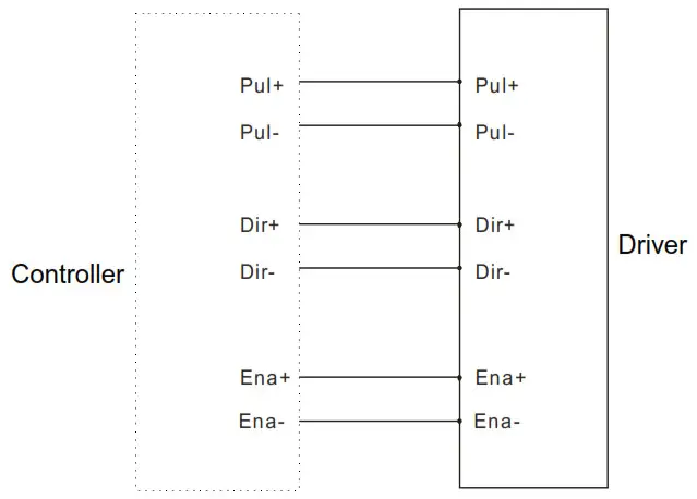
Control signal connection
PUL, DIR Port: connection for pulse command
The signal interface of the standard R series driver is in the form of a pulse, and the R86 can receive two kinds of pulse command signals.
The upper controller can be the pulse signal generating devices, such as PLC, MCU, control card, and controller.
The pulse level that R86 driver can be used: 3.3V-24V (no need to connect resistor)
| Pulse and direction (PUL + DIR) | 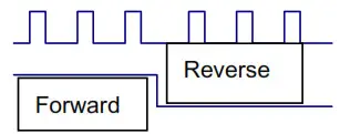 |
| Double pulse (CW +CCW) | 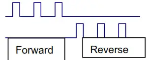 |
ENA port: enable/disable
By default, when the internal optocoupler is off, the driver outputs current to the motor;
When the internal optocoupler is on, the driver will cut off the current of each phase of the motor to make the motor free, and the step pulse will not be responded to.
When the motor is in an error state, ENA input can be used to restart the drive. Firstly, the fault is eliminated, and then a falling edge signal is an input to the ENA terminal. The driver can restart the power part and the motor is excited.
The level logic of the ENA signal can be set to the opposite, with the logic being opposite to the above.
Examples for control signal connection
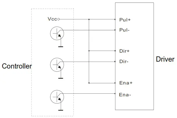
Common Anode
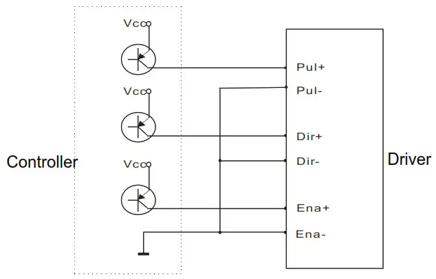
Common Cathode
The setting of DIP switches and operating parameters
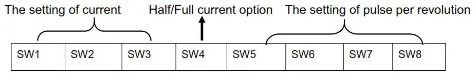
The setting of current
| Peak Current | Average Current | SW1 | SW2 | SW3 | Remarks |
| 2.4A | 2.0A | on | on | on | Other Current can be customiz ed |
| 3.1A | 2.6A | off | on | on | |
| 3.8A | 3.1A | on | off | on | |
| 4.5A | 3.7A | off | off | on | |
| 5.2A | 4.3A | on | on | off | |
| 5.8A | 4.9A | off | on | off | |
| 6.5A | 5.4A | on | off | off | |
| 7.2A | 6.0A | off | off | off |
DIP SW1, SW2, SW3 are used to set the current which is output from the driver to the motor. Generally, the current is set to the rated current of the motor. If your system has a high request for heating, please decrease the current properly to lower the motor’s heating, but at the same time, the output torque will be lower. If you don’t need the motor running continuo us, you can increase the current to higher the torque. But be minded that the current can not be 1.5 times over the rated current.
The setting of pulse per revolution
| Steps/revolution | SW5 | SW6 | SW7 | SW8 | Remarks |
| Default | on | on | on | on | Other subdivisions can be customized. |
| 800 | off | on | on | on | |
| 1600 | on | off | on | on | |
| 3200 | off | off | on | on | |
| 6400 | on | on | off | on | |
| 12800 | off | on | off | on | |
| 25600 | on | off | off | on | |
| 51200 | off | off | off | on | |
| 1000 | on | on | on | off | |
| 2000 | off | on | on | off | |
| 4000 | on | off | on | off | |
| 5000 | off | off | on | off |
| 8000 | on | on | off | off |
| 10000 | off | on | off | off |
| 20000 | on | off | off | off |
| 40000 | off | off | off | off |
DIP SW5, SW6, SW7, and SW8 are used to set the pulse per revolution required by the motor.
Motor speed = command pulse frequency ÷ pulse per revolution
Motor stroke = number of command pulses ÷ pulse per revolution
The selection of Half/Full Current
DIP SW4 is used to set the static current value when the motor is stopped
Off means that when the driver’s power-on pulse stops, the driver switches the current output to the motor to half (half current) when it is rotating;
On means that when the driver’s power-on pulse stops, the driver maintains the same current output to the motor as the rotation (full current) . In general use, SW4 should be set to off, so that the heat of the motor and driver is reduced, and the reliability is improved.
Driver working status LED indication
LED status | Driver status | |
| Green indicator is on for a long time | Driver not enabled | |
 | Green indicator is flickering | Driver working normally |
| One green indicator and one red indicator | Driver overcurrent | |
 | One green indicator and two red indicators | One green indicator and two red indicators |
| One green indicator and three red indicators | The internal voltage of the driver is wrong | |
Common faults and troubleshooting
| Phenomenon | Possible situations | Solutions |
| Motor does not work | Power indicator is off | Check the power supply circuit for normal power supply |
| The motor rotor is locked but the motor does not work | Pulse signal is weak: increase the signal current to 7-16mA | |
| The speed is too slow | Select the right micro-stepping | |
| Driver is protected | Solve the alarm and re-power | |
| Enable signal problem | Pull up or disconnect the enable signal | |
| Command pulse is incorrect | Check whether the upper computer has a pulse output | |
| The steering of motor is wrong | The rotary direction of the motor is reverse | Adjust the DIP SW5 |
| The motor cable is disconnected | Check the connection | |
| The motor has only one direction | Pulse mode error or DIR port damaged | |
| Alarm indicator is on | The motor connection is wrong | Check the motor connection |
| The motor connection and encoder connection are wrong | Check the sequence of encoder connection | |
| The voltage is too high or too low | Check the power supply | |
| The position or speed is wrong | The signal is disturbed | Eliminate interference for reliable grounding |
| The command input is incorrect | Check the upper computer instructions to ensure the output is correct | |
| The setting of Pulse per revolution is wrong | Check the DIP switch status and correctly connect the switches | |
| Encoder signal is abnormal | Replace the motor and contact the manufacturer | |
| The driver terminal burned | Sho circuit between terminals Short | Check power polarity or external short circuit |
| up | Internal resistance between terminals is too large | Check whether there is any solder ball due to excessive addition of solder on the wire connections |
| The motor is out of tolerance | Acceleration and deceleration time is too short | Reduce command acceleration or increase Driver filtering parameters |
| Motor torque is too low | Select the motor with high torque | |
| The load is too heavy | Check the load weight and quality and adjust the mechanical structure | |
| The current power supply is too low | Replace the appropriate power supply |
Guarantee clause
Warranty period: 12 months
We provide quality assurance for one year from the date of delivery and free maintenance service for our products during the warranty period.
Exclude the following:
- Improper connection, such as the polarity of the power supply is reversed and insert/pull the motor connection when the power supply is connected.
- Beyond electrical and environmental requirements.
- Change the internal device without permission.
Maintenance process
For maintenance of products, please follow the procedures shown below:
- Contact our customer service staff to get the rework permission.
- The written document of the Driver failure phenomenon is attached to the goods, as
well as the contact information and mailing methods of the sender.
Mailing address:
Postcode:
Tel.:


