MIKSTER INDU-50 Microprocessor Controller
Product Information
The INDU-50 Controller is a user-friendly device designed for controlling and regulating industrial applications. It features a user-friendly operator panel, service functions, and alarms for easy monitoring and control. The controller also comes with pasteurization features and governor diagrams for precision control of industrial processes.
Product Usage Instructions
- Introduction: Read the user manual carefully before using the INDU-50 Controller. Ensure that the controller is installed and assembled correctly before powering it on.
- Elements: Familiarize yourself with the different parts of the controller, including the operator panel, governor diagrams, and relays.
- Assembly: Follow the assembly instructions provided in the user manual to ensure proper installation of the controller.
- Startup: Power on the controller and ensure that it is functioning correctly. The controller should display the correct setup options on the operator panel.
- Operator panel: Use the operator panel to monitor and control industrial processes. The panel displays information about the setup options, pasteurization, and alarms.
- Operation description: Choose between INFO mode, AUTOSTART mode, and START mode to control industrial processes. Use the service functions to access additional controls and options.
- Pasteurization: Use pasteurization features to ensure that industrial processes comply with safety standards.
- Governor diagrams: Use the governor diagrams to monitor and control industrial processes with precision.
- Selection of governor setup PID: Choose the governor setup PID that best suits the industrial process being controlled.
- Controller setup: Configure the controller to suit the industrial process being controlled. Use the setup options to adjust parameters like temperature and pressure.
- Relays: Use the relays to control external devices like valves and pumps.
- Example of application: Refer to the example of the application provided in the user manual for guidance on how to use the controller to control specific industrial processes.
By following these instructions, you can effectively use the INDU-50 Controller to control and regulate industrial processes with precision and ease.
Introduction
- Thank you for choosing and purchasing the Industrial Microprocessor Controller INDU-50. We hope that You will find our product to be reliable and easily operated.
- Please read carefully the User’s manual. This will enable You to obtain the best effects in using the system and to prolong the service life of devices.
- Microprocessor controller INDU-50 is intended for servicing heat boilers, smoke houses, cooking ovens.
- INDU controllers constitute series of industrial microprocessor devices, in which the special emphasis has been laid on the proper operation at difficult environment conditions. INDU series comprises such devices as governors, digital recorders, indicators.
- Microprocessor controller INDU-50 cooperates with computer software, with INDU monitor and Loggisoft from version 2.12 (or higher). Versions of software are available, free of charge, on www.mikster.eu

- Controller user’s manual INDU-50 v1.95(86)EN


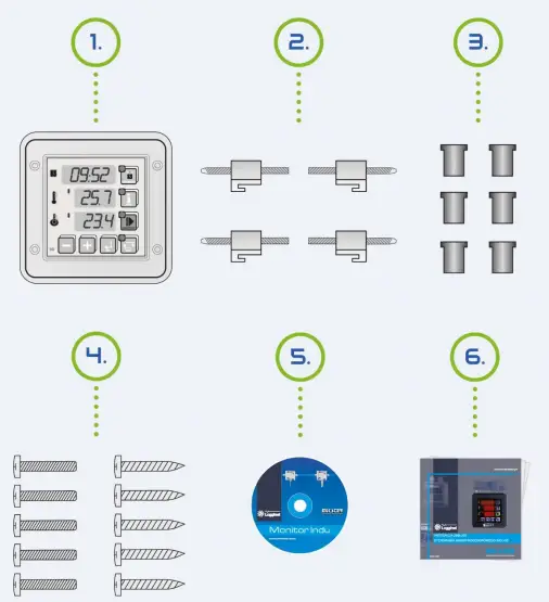

Elements
The UNDU-50 consists od the following elements:
- Industrial Microprocessor Controller INDU-50 – 1 item,
- Clamping elements – 4 item,
- Mask elements – 6 item,
- Clamping screw – 10 item,
- CD with Loggisoft LT software,
- User’s manual,
- Plug AKZ950x14 – 1 item,
- Plug AKZ950x12 – 1 item,
- Plug AKZ950x2 – 1 item,
Assembly
ATTENTION!
The Silicon washer should be lubricated by technical vaseline. Be aware that the washer should accurately adhere to the assembling surface. 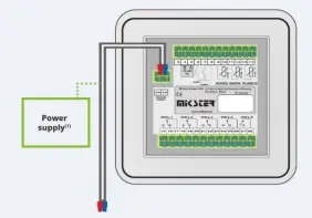
ATTENTION!
- Before connecting, verify the supply voltage on the device label. Depending on the version: 230V AC, 110-230V AC, 24V AC, 24V AC/DC
Startup
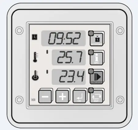
- After connecting the temperature sensors (standard: PT-100) and power supply, the controller is switched on automatically. After displaying a “welcome” text the current hour, minute, channel 1 and channel 2 measurements are displayed consecutively.
- When the display shows “—”, the controller indicates that a measuring element is missing or damaged.
- Diodes located at keys indicate current status of the device (e.g. edit or auto start mode). Horizontal lines on the left side of displayed measured value indicate regulator status: diode on signals that an output is programmed. Key LEDS indicates the current operating mode. The following modes can be indicated: AUTOSTART, START, INFO, and EDIT.
- In the STOP mode, after the START mode is completed, the display shows instead of hour and minute.


ATTENTION!
In case of power failure the controller saves in memory its current operating mode and when power is back, it returns to the same mode (unless time set in cell 48 — Setup has passed).
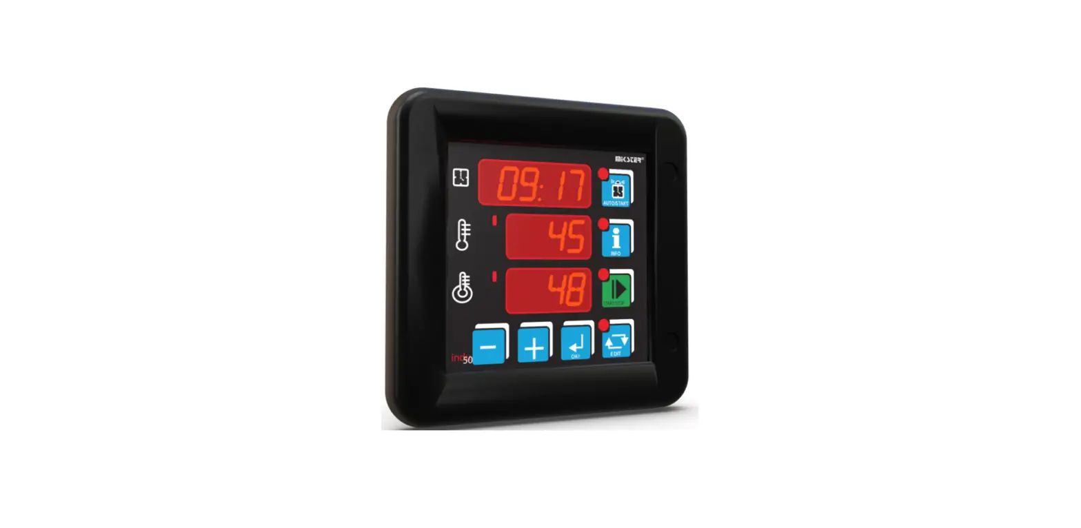
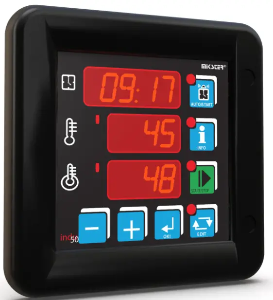
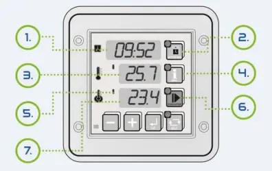
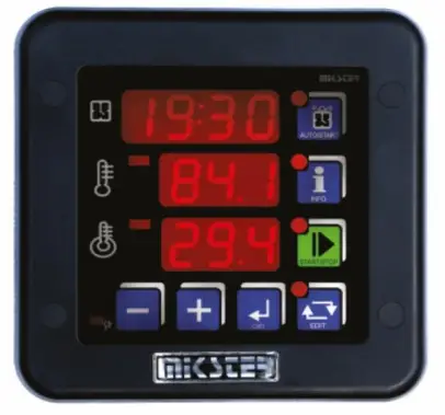
Operator panel
- Clock RTC/Process time
- AUTOSTART mode key
- Boiler temperature – Channel 1
- INFO mode key
- Bar temperature
- START mode key
- Meat-bar temperature Channel 2/ counted pasteurization number

Operation description
EDIT mode – setpoint changing
- To get into the setpoint edit mode press the EDIT key.

- When the edit mode is activated, the EDIT key flashes.

- You can change the parameters on the display by using the keyboard.

- To confirm or move to the next field, press
 to exit press.
Setpoint sequence:
- START mode duration (hours: minutes)
- controller temperature setpoint based on channel 1
- controller temperature setpoint based on channel 2
ATTENTION!
- Channel 3 temperature setpoint can be entered in the SETUP menu (item SF38).
INFO mode
- Press the key
 to recall information depending on the current controller operating mode.
For the AUTOSTART mode
- According to the setting in the Setup menu, item SF47:
- For HMD — hour, minute, and daily delay when the START mode is to be activated
- For HM — hours and minutes to the START mode
Other information is identical for each mode:
- channel 3 measurement (Ad-3), Measurement on channel 2; the calculated jacket temperature setpoint**
- channel 1 and channel 2 temperature setpoints
- current date
- current time
- To get the next (previous) information, press
AUTOSTART mode
- Press the
 key to edit parameters for this mode.
 - AUTOSTART mode can be activated in two ways:
 key to edit parameters for this mode.
- At a specified time (hour and minute) and daily delay, if any (F47 SETUP – HMD).
- After counting down a specified time (hours and minutes) (F47 SETUP – HM)
- Pressing the START button during edit mode causes the beginning of waiting mode for START (AUTOSTART). To quit the AUTOSTART mode,press the key once again. You can switch immediately from the AUTOSTART mode into the START mode by pressing the START key.
START mode
- To start and end the START mode, press the key.
 For typical controller settings after switching into the START mode all regulators are activated and the process time counting down is started. The time in hours and minutes to the process end is shown on the display.
 - Depending on the SETUP configuration the following process end conditions may occur.
- after process time elapsing (process timeout)
- after the required bar temperature is reached
- obtaining the required pasterisation number
- The process end is indicated with an internal audible signal and by closing the REL5 Output To switch audible signal off, press.

Service functions accessible to the user
| Cell no | Description |
| UF0 | Real-time clock setting press |
| UF1 | Access code changing to the user’s function Range 0..999 Value 0 – access code off |
| UF2 | Information on software version |
| UF3 | Keyboard click ON/OFF |
- To get into the user’s setting press and hold down the key
 and then press and hold down the key.
- The functions mentioned above are available after the access code is entered. To disable the access code verification function, set the access code at 0000 for the user’s function. By default, the access code for service functions available to the user is disabled.
Alarms
The INDU 50 Controller recognizes 11 alarm events:
| Err 1 | Measuring element missing or damaged in channel 1 |
| Err 2 | Measuring element missing or damaged in channel 2 |
| Err 3 | Measuring element missing or damaged in channel 3 |
| Err 4 | MAX temperature exceeded in channel 1 |
| Err 5 | MAX temperature exceeded in channel 2 |
| Err 6 | MAX temperature exceeded in channel 3 |
| Err 7 | Temperature below MIN in channel 1 |
| Err 8 | Temperature below MIN in channel 2 |
| Err 9 | Temperature below MIN in channel 3 |
| Err 10 | Control input 1 alarm (depends on SF69 settings) |
| Err 11 | Control input 2 alarm (depends on SF70 settings) |
To activate alarms it is necessary first to set alarm activation time [seconds] in SETUP (items 71..73), and then enable the selected alarms in SETUP (items SF60..SF70). Any alarm shall be acknowledged by pressing. ![]() If the cause of the alarm has not been cleared, then the controller activates the alarm once again after the activation delay time.
If the cause of the alarm has not been cleared, then the controller activates the alarm once again after the activation delay time.
Pasteurization
- Due to the frequent application of the INDU50 controller as a unit controlling the process of thermal food processing, its properties were widened by the possibility of counting the pasteurization number according to the arithmetic variant of the general method.
- The following sterilization coefficients were applied: (z = 4.8K; z = 7.78K; z = 10K; z = 15K; z = 25K; z = 33,34K — set in Setup; cell SF80) for the process temperature
- Tr also set in Setup SF77. There is a possibility of performing the process either on the bases of the set value of the pasteurization number only (Setup SF76) or on the bases of the set value of the pasteurization number and the processing time. In the second case, the parametrization of maximum process time can constitute additional protection of the production process’s correctness. The setting of the adequate integration time, which means the time between consecutive moments of counting pasteurization number (setup cell SF79), was also taken into account in the INDU50 controller. The possibility of determining the temperature, from which the controller should start counting the pasteurization number (Setup SF81) was also added. In order to utilize the INDU50 controller for counting the pasteurization number the Setup cell SF45 – a condition of ending START mode – should be set on 19 or 20. The pasteurization number is determined in Setup SF76.
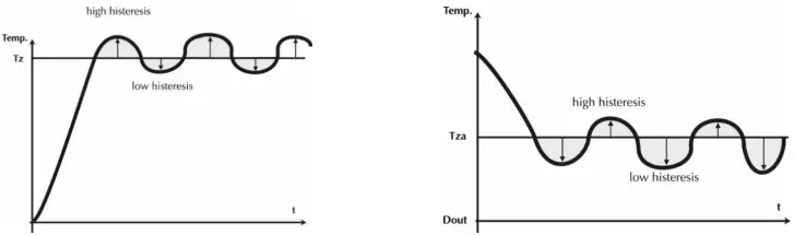
Governor diagrams
- Governor – simple histeresis – heating Type 0*
- Governor – reversed histeresis – refrigeration Type 1*

- Tz – temperature setpoint t – time
- Tz – temperature setpoint t – time
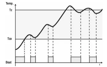
- Governor – simple histeresis – algorithm of temperature approaching Type 2*
- Temperature control can be divided into three zones. In the first zone the output Dout is controlled until Tza temperature is reached. Above the Tza temperature, in the second zone, the algorithm of temperature approaching the set value id realized. In the third zone the temperature in between the lower and upper histeresis is kept.
- Governor of temperature approaching

- Tz – temperature setpoint t – time Tza – thershold tempereature for triggering the „approach” algorithm (for temp. below Tza-Dout output is permanently on) Dout – state at binary output (high state corresponds with the activation of heaters)
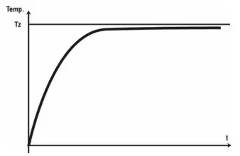
- Governor PID Type 3*

- Tz – temperature setpoint t – time
Governor relative Type 4
- Governor dedicated for jacket temperature control in parboilers. Jacket temperature control is carried out on the basis of the relationship between the preset and the read-out water temperature.
ATTENTION!
- This type of governor is only available on channel 3 (cell setting SF31); controller configuration parameters: SF87,103, SF104, SF105.
Selection of governor setup PID
- To obtain access to the governor setup PID coupled with the given measuring channel the key should be pressed and held and then the key. Information concerning the given parameter and the governor number will appear on the upper display.

- Edition of the selected parameter is done on the middle display (pulsating value). Increase of parameter Value by the key, decrease by the key. Shift to the next parameter and confirmation of changes by the key. Exit from edition mode by pressing the key.

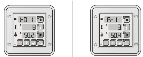
Regulation is being done on the basis of:
- To – sampling period
- Pr – strengthening of a proportional element
- Ti – integration constant (doubling time)
- Td – differentiation constant (advancing time)
- Ts – set temperature
Controller setup
- To get into the SETUP menu, press and hold down the key and then press the key. After entering the access code (if included in Setup cell SF 74) you can change the controller parameters.
| No. | Default value | Range | Description | User settings |
| SF0 | 1 | 0..128 | MODBUS network address | |
| SF1 | 0 | 0..4 | Baud rate 0-9600, 1-19200, 2-38400, 3-57600, 4-115200 | |
| SF2 | 1 | 0..12 | Channel 1 measuring input type Standard version: · 0 – PT-500 · 1 – PT-100 · 2 – PT1000
FULL CALIBRATION version (special order) · 3 – 0..20mA · 4 – 4..20mA · 5 – thermocouple s · 6 – thermocouple b · 7 – thermocouple r · 8 – thermocouple t · 9 – thermocouple j · 10 – thermocouple e · 11 – thermocouple k · 12 – thermocouple n | |
| SF3 | 1 | 0..12 | Measuring input type for channel 2 | |
| SF4 | 1 | 0..12 | Measuring input type for channel 3 | |
| SF5 | 0°C | -99,0..999°C | Value corresponding to 0 mA for channel 1 0..20 mA input | |
| SF6 | 200°C | -99,0..999°C | Value corresponding to 20 mA for channel 1 0..20 mA input | |
| SF7 | 0°C | -99,0..999°C | Value corresponding to 0 mA for channel 2 0..20 mA input | |
| SF8 | 200°C | -99,0..999°C | Value corresponding to 20 mA for channel 2 0..20 mA input | |
| SF9 | 0°C | -99,0..999°C | Value corresponding to 0 mA for channel 3_0..20 mA input | |
| SF10 | 200°C | -99,0..999°C | Value corresponding to 20 mA for channel 3_0..20 mA input | |
| SF11 | 0°C | -99,0..999°C | Value corresponding to 4 mA for channel 1 4..20 mA input | |
| SF12 | 200°C | -99,0..999°C | Value corresponding to 20 mA for channel 1 4..20 mA input | |
| SF13 | 0°C | -99,0..999°C | Value corresponding to 4 mA for channel 2 4..20 mA input | |
| SF14 | 200°C | -99,0..999°C | Value corresponding to 20 mA for channel 2 4..20 mA input | |
| SF15 | 0°C | -99,0..999°C | Value corresponding to 4 mA for channel 3 4..20 mA input |
| No. | Default value | Range | Description | User settings | |
| SF16 | 200°C | -99,0..999°C | Value corresponding to 20 mA for channel 3 4..20 mA input | ||
| SF17 | 0,0°C | -20,0..20°C | Temperature readout adjustment for channel 1 | ||
| SF18 | 0,0°C | -20,0..20,0°C | Temperature readout adjustment for channel 2 | ||
| SF19 | 0,0°C | -20,0..20,0°C | Temperature readout adjustment for channel 3 | ||
| SF20 | On | On / Off | Regulator operation in channel 1 | ||
| Off –always | On – only in the START mode | ||||
| SF21 | On | On / Off | as above for channel 2 | ||
| SF22 | On | On / Off | as above for channel 3 | ||
| SF23 | -99°C | -99..400°C | Minimum allowable setpoint for channel 1 | ||
| SF24 | 150°C | -99..400°C | Maximum allowable setpoint for channel 1 | ||
| SF25 | -99°C | -99..400°C | Minimum allowable setpoint for channel 2 | ||
| SF26 | 150°C | 400°C | Maximum allowable setpoint for channel 2 | ||
| SF27 | – | – | – | ||
| SF28 | – | – | – | ||
| SF29 | 0 | 0..3 | Regulator type for channel 1 · 0 – normal hysteresis · 1 – reversed hysteresis · 2 – normal hysteresis, ’setpoint ramping” algorithm · 3 – PID regulator · 4* – relative regulator (only available for channel 3) | ||
| SF30 | 0 | 0..3 | Regulator type for channel 2 | ||
| SF31 | 0 | 0..4* | Regulator type for channel 3 | ||
| SF32 | 1,0°C | 0,0..5,0°C | Low hysteresis for channel 1 | ||
| SF33 | 1,0°C | 0,0..5,0°C | Low hysteresis for channel 2 | ||
| SF34 | 1,0°C | 0,0..5,0°C | Low hysteresis for channel 3 | ||
| SF35 | 1,0°C | 0,0..5,0°C | High hysteresis for channel 1 | ||
| SF36 | 1,0°C | 0,0..5,0°C | High hysteresis for channel 2 | ||
| SF37 | 1,0°C | 0,0..5,0°C | High hysteresis for channel 3 | ||
| SF38 | 120°C | -99..999°C | Channel 3 temperature setpoint | ||
| No. | Default value | Range | Description | User settings |
| SF39 | 20°C | 0..200°C | Regulator activation temperature (Tza) for channel 1 For “setpoint ramping” algorithm | |
| SF40 | 20°C | 0..200°C | Regulator activation temperature (Tza) for channel 2 For “setpoint ramping” algorithm | |
| SF41 | 20°C | 0..200°C | Regulator activation temperature (Tza) for channel 3 For “setpoint ramping” algorithm | |
| SF42 | 1 | 0..100 sek | Regulator activation delay [seconds] for channel 1 | |
| SF43 | 1 | 0..100 sek | Regulator activation delay [seconds] for channel 2 | |
| SF44 | 1 | 0..100 sek | Regulator activation delay [seconds] for channel 3 | |
| SF45 | 5 | 0..21 | START mode end conditions see “CYCLE END CONDITIONS” | |
| SF46 | 1 | 0..1 | Recording · 0 – continuous recording · 1 – recording in the START mode only | |
| SF47 | HMd | HMd/HM | AUTOSTART mode parameter format · HMD – hour, minute and daily delay for START · HM – ours and minutes to START | |
| SF48 | 5 | 0..10 godz. | Maximum time period after which the controller returns to the START mode (after power failure) | |
| SF49 | 1 | 1..360 min | Measurement recording frequency (unit defined in SF89: min, sec) | |
| SF50 | 1 | 1..360 min | Alarm recording frequency | |
| SF51 | C | C / F | Temperatur unit | |
| SF52 | 1 [min] | 0..99 [min] | Audible signal duration Note! If 0 is selected, then the signal is cancelled with the OK key! | |
| SF53 | 1 | 0 .. 1 | Alarm output operating mode · 0 –interrupted signal · 1 –continuous signal | |
| SF54 | 150°C | -99..999°C | Maximum allowable (alarm) temperature for channel 1 | |
| SF55 | 150°C | -99..999°C | Maximum allowable (alarm) temperature for channel 2 | |
| SF56 | 150°C | -99..999°C | Maximum allowable (alarm) temperature for channel 3 | |
| SF57 | -99°C | -99..999°C | Minimum allowable (alarm) temperature for channel 1 | |
| SF58 | -99°C | -99..999°C | Minimum allowable (alarm) temperature for channel 2 | |
| SF59 | -99°C | -99..999°C | Minimum allowable (alarm) temperature for channel 3 | |
| SF60 | Off | On / Off | Sensor fault alarm activation for channel 1 | |
| SF61 | Off | On / Off | Sensor fault alarm activation for channel 2 | |
| SF62 | Off | On / Off | Sensor fault alarm activation for channel 3 |
| No. | Default value | Range | Description | User settings |
| SF63 | Off | On / Off | Maximum temperature exceeded alarm activation for channel 1 | |
| SF64 | Off | On / Off | Maximum temperature exceeded alarm activation for channel 2 | |
| SF65 | Off | On / Off | Maximum temperature exceeded alarm activation for channel 3 | |
| SF66 | Off | On / Off | Maximum allowable (alarm) temperature for channel 1 | |
| SF67 | Off | On / Off | Maximum allowable (alarm) temperature for channel 2 | |
| SF68 | Off | On / Off | Maximum allowable (alarm) temperature for channel 3 | |
| SF69 | 0 | 0..4 | Alarm activation on control input 1 · 0 – alarm disabled · 1 – alarm when inputs 6-8 are close · 2 – alarm when inputs 6-8 are open · 3 – keyboard blocking when inputs 6-8 shorted · 4 – keyboard blocking when inputs 6-8 not shorted | |
| SF70 | 0 | 0..4 | Alarm activation on control input 2 · 0 – alarm disabled · 1 – alarm when inputs 7-8 are close · 2 – alarm when inputs 7-8 are open · 3 – keyboard blocking when inputs 7-8 shorted · 4 – keyboard blocking when inputs 7-8 not shorted | |
| SF71 | 60 | 0..999 sek | Sensor fault alarm indication delay | |
| SF72 | 60 | 0..999 sek | Temperature exceeded alarm indication delay. | |
| SF73 | 60 | 0..999 sek | Control input alarm indication delay | |
| SF74 | 0 | 0..999 | SETUP access code change | |
| Value 0 – code check OFF | ||||
| SF75 | 0 | 0..1 | Time base for START mode · 0 – hour:min · 1 – min:sec | |
| SF76 | 66,4 | 0,1..999, 1 min | Set pasterisation number | |
| SF77 | 72°C | 0..100°C | Pasterisation temperature (Process temperature Tr) | |
| SF78 | 0 | 0..2 | The channel on which the temperature inside the box is measured. · 0 – channel 1 · 1 – channel 2 · 2 – channel 3 | |
| SF79 | 15 | 0..600 sek | Setting the reading rate of the pasterisation number (seconds) |
| SF80 | 0 | 0..5 | Selection of sterilisation coefficients table for: · 0 – coefficient z=4,8 K · 1 – coefficient z=7,78 K · 2 – coefficient z=10 K · 3 – coefficient z=15 K · 4 – coefficient z=25 K · 5 – coefficient z=33,34 K | |
| SF81 | 52°C | 0..100°C | Temperature, from which the governor starts counting the pasterisation number | |
| SF82 SF83 SF84 | 0
1
2 | 0..2
0 ..2
0..2 | Number of the measuring channel versus which the regulation is carried on governor 1 Number of the measuring channel versus which the regulation is carried on governor 2 Number of the measuring channel versus which the regulation is carried on governor 3 · 0 – measuring channel 1 · 1 – measuring channel 2 · 2 – measuring channel 3 | |
| SF85 SF86 SF87 | 0 0 0 | -50..100°C -50..100°C -50..100°C | Shifting of the set temperature for governor 1 Shifting of the set temperature for governor 2 Shifting of the set temperature for governor 3 | |
| SF88 | 0 | 0..4 | Process triggering method · 0 – START key · 1 – Input 1 · 2 – Input 2 · 3 – Input 1 or 2 · 4 – Input 1 or 2 | |
| SF89 | 0 | 0..1 | Measurement recording frequency unit (applies to SF49): · 0 – min · 1 – sec | |
| SF90 | 0 | 0..1 | Time display method · 0 – countdown · 1 – forward countdown | |
| SF91 SF92 SF93 | 10 s 10 s 10 s | 10..1000 s 10..1000 s 10..1000 s | Cycle time of digital output – Governor PID1 Cycle time of digital output – Governor PID2 Cycle time of digital output – Governor PID3 | |
| SF94 SF95 SF96 | 0 s 0 s 0 s | 0..120 s 0..120 s 0..120 s | Minimum heating time – Governor PID1 Minimum heating time – Governor PID2 Minimum heating time – Governor PID3 | |
| SF97 SF98 SF99 | 0 s 0 s 0 s | 0..120 s 0..120 s 0..120 s | Minimum period interval time – Governor PID1 Minimum period interval time – Governor PID2 Minimum period interval time – Governor PID3 | |
| SF100 SF101 SF102 | 0 s 0 s 0 s | 0..120 s 0..120 s 0..120 s | Purge time – Governor PID1 Purge time – Governor PID2 Purge time – Governor PID3 | |
| SF103 | 5,2 | 0..99,9 | Relative governor gain | |
| SF104 | 30 s | 0..120 s | Minimum burner start-up time for the relative governor | |
| SF105 | 30 s | 0..120 s | Minimum burner switch-off time for the relative governor |
Relays
| REL 1 | Relay output of governor 1 |
| REL 2 | Relay output of governor 2 |
| REL 3 | Relay output of governor 3 |
| REL 4 | Switched on in START mode |
| REL 5 | Alarm |
Example of application
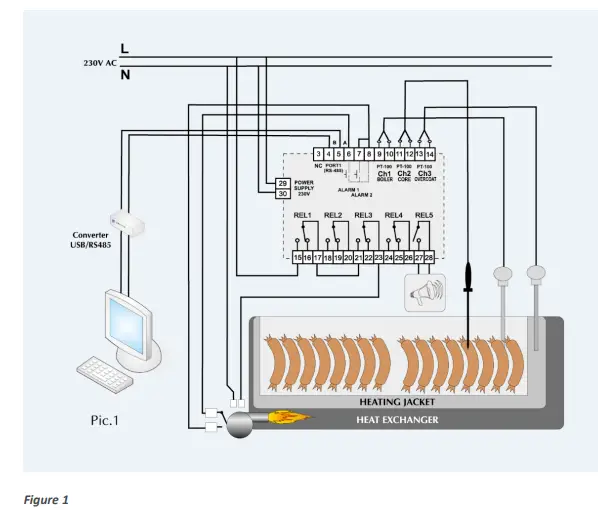
Pic. 1. this example is given for informative purpose only and should not be considered in part or in whole as a system design
Cycle end conditions
| Nr | Cycle end conditions (cell Setup 45) |
| SF45=0 | Timeout (time elapsed) |
| SF45=1 | Cycle ends when temperature setpoint is exceeded in channel 1 (boiler) |
| SF45=2 | Cycle ends when temperature setpoint is exceeded in channel 2 (bar) |
| SF45=3 | Cycle ends when temperature setpoint is exceeded in channel 3 (shell) |
| SF45=4 | Cycle ends after the preset time is elapsed or temperature setpoint is exceeded (boiler) |
| SF45=5 | Cycle ends after the preset time is elapsed or temperature setpoint is exceeded (bar) |
| SF45=6 | Cycle ends after the preset time is elapsed or temperature setpoint is exceeded (shell) |
| SF45=7 | Cycle ends after the preset time is elapsed and temperature setpoint is exceeded (boiler) |
| SF45=8 | Cycle ends after the preset time is elapsed and temperature setpoint is exceeded (bar) |
| SF45=9 | Cycle ends after the preset time is elapsed and temperature setpoint is exceeded (shell) |
| SF45=10 | Cycle ends when the boiler temperature drops below the setpoint |
| SF45=11 | Cycle ends when the bar temperature drops below the setpoint |
| SF45=12 | Cycle ends when the shell temperature drops below the setpoint |
| SF45=13 | Cycle ends after the preset time is elapsed or the boiler temperature drops below the setpoint |
| SF45=14 | Cycle ends after the preset time is elapsed or the bar temperature drops below the setpoint |
| SF45=15 | Cycle ends after the preset time is elapsed or the shell temperature drops below the setpoint |
| SF45=16 | Cycle ends after the preset time is elapsed and the boiler temperature drops below the setpoint |
| SF45=17 | Cycle ends after the preset time is elapsed and the bar temperature drops below the setpoint |
| SF45=18 | Cycle ends after the preset time is elapsed and the shell temperature drops below the setpoint |
| SF45=19 | End of a cycle, when the pasterisation number is reached. |
| SF45=20 | End of a cycle, when either the pasterisation number or the set time is reached. |
| SF45=21 | End of cycle when, after reaching the bar temperature, the set time is counted down. |
The most frequently asked questions (FAQ)
| 1. What to do when the governor does not switch on? |
| · Check the power supply of the governor. |
| 2. The governor does not record the data after the end of the process. |
| · Check the setting of the SF46 cell. If continuous recording is required, · which means recording regardless of the operation mode, write 0. |
| 3. Is it possible to ommit the access code to service functions accessible for the user? |
| · Write 0 (zero) as the access code of the governor. |
| 4. Transmission in RS485 network does not operate. |
| · Check addresses in RS485 network. Attention! Each device must have an individual address. · The problem may also be: – incorrectly set baud rate in the governor, swapped A and B signals, damaged transmission line, and many others. |
| 5. Temperature sensor PT-100, PT-500 or PT-1000 does not operate. |
| · Check the setting correctness for the temperature sensor, e.g. for the first sensor, PT-100, value 1 should be set in cell SF2. |
Technical data
| Power supply: | 24V AC/DC Imax.140mA 110/230VAC Imax.30mA |
| Display: | 3x LED 0,5″ Red |
| Keyboard: | micro switch buttons |
| Connectors: | plug-in terminal blocks |
| Temperature measuring range: | – 99°C ÷ 600°C |
| Temperature measurement resolution: | 0,1°C od – 9,9°C to 99,9°C 1°C in other ranges |
| Temperature measurement error: | ≤ ±0,5°C (applies to the measuring circuit of the controller) |
| Inputs: | 3 measuring analogue configurable (PT100/PT500/PT1000) · PT100/PT500/PT1000 – standard version · 0..20mA, 4..20mA, thermocouple: s, b, r, t, j, e, k, n – FULL CALIBRATION version (special order) 2 potential free digital (control) |
| Outputs: | 4 switch relay digital (max load 250VAC/2A per channel) 1 NO relay digital (max load 250VAC/2A) |
| Communication: | 1xRS485 |
| Registration: | 100 000 records |
| Software: | LoggisoftLT (PC) , MPC4 (PC) |
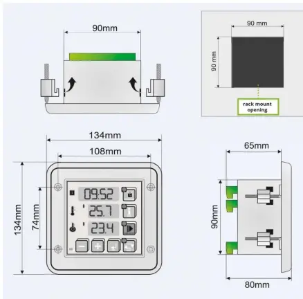
| Dimensions: | external 134x134x65mm (W x H x D) mounting 90x90mm (W x H) |
| Fixing: | screwed 4 mounting holes (front) or 4 mounting clips (rear) |
| Weight: | 500 g (net) |
| IP rating: | 65 (front) 20 (rear) |
| Operating conditions: | Temperature: 0°C ÷ 55°C Humidity: 5%RH ÷ 85%RH |
| EC compliance: | 2014/30/UE ROHS 2011/65/UE 2014/35/UE PN-EN IEC 61000-6-2:2019 PN-EN 61000-4-4:2013-05 PN-EN 61000-4-2:2011 PN-EN 61000-4-11:2007 PN-EN 61131-2:2008 |
Features

- from the front IP 65 the front – the resistance to strong cleaning agents used in the food industry
Transmission parameters
Transmission characteristics
- Interface: RS-485
- Transmission protocol: MODBUS RTU
- Transmission parameters: 1 start bit, 8 data bits, 2 stop bits, without parity check
- Transmission speed: 9600 bit/sec
Measurement results readout
| Adress | Function | Sub- function | Length H | Length L | Data | CRC L | CRC H |
| 8 bits | 8 bits | 8 bits | 8 bits | 8 bits | 8 bits | 8 bits | 8 bits |
Designations
- ADRESS – address of the SLAVE device
- FUNCTION – function number
- SUB-FUNCTION – sub-function number
- LENGTH (H, L) – total frame length
- DATA – N-bytes of data
- CRC (H, L) – low byte and high byte CRC 16
- Sub-functions for the measurement readout function: 46 HEX (70 DEC) Measurement results readout
| Sub-functions number | Feedback | Interpretation | Length | Byte number in the frame (*) |
| 0 HEX (0 DEC) | measurement results readout | Channel 1 *10 (entry in the complementary code to 2) | 2 bytes | 5 6 |
| Channel 2 *10 (entry in the complementary code to 2) | 2 bytes | 7 8 | ||
| Channel 3 *10 (entry in the complementary code to 2) | 2 bytes | 9 10 |
Attention!
- Value 0xF448 on any of the channels means no measurement (defective sensor or no sensor). Example of a query (values in HEX): 01 46 00 00 07 4D 4A.


CUSTOMERS WHO TRUST OUR QUALITY ARE ALL OVER THE WORLD
- EUROPE
- Hungary
- Uzbekistan
- Bahamas
- Germany
- Greece
- Azerbaijan
- CENTRAL AMERICA
- France
- Croatia
- Kazachstan
- Belize
- United Kingdom
- Romania
- Turkmenistan
- SOUTH AMERICA
- Sweden
- Portugal
- Vietnam
- Bolivia
- Switzerland
- Bulgaria
- India
- AUSTRALIA
- Austria
- Slovenia
- Israel
- Chester Hill
- Denmark
- Slovakia
- Pakistan
- Guildford
- Belgium
- Turkey
- Malaysia
- Bundaberg, Qld
- Netherlands
- Latvia
- Thailand
- Keysborough
- Norway
- Czech Republic
- Georgia
- Moonah
- Poland
- Belarus
- AFRICA
- Mosman
- Estonia
- Ukraine
- Mauritius
- Palmyra
- Ireland
- ASIA
- South Africa
- Romania
- Russia
- NORTH AMERICA
- Moldova
- China
- Canada
- Lithuania
- United Arab Emirates
- USA
- Spain
- Japan
- Virgin Islands
- MISTER SP. Z 0.0.
- Wojkowicka 21,
- 41-250 Czeladz, Polska
- VAT ID: PL9542113188
- REGION: 273545050
- +48 32 763 77 77
- 18 +48 32 763 75 94
- [email protected]
- www.mikster.eu


