Haloview Handy5 2.4g Digital 720p 5 Inch-7 Inch Lcd Wireless Monitor User Manual

Haloview Handy5 2.4g Digital 720p 5 Inch-7 Inch Lcd Wireless Monitor User Manual

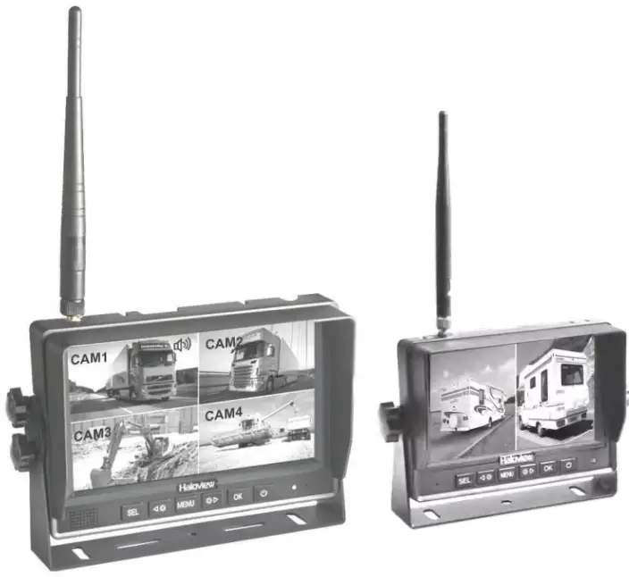
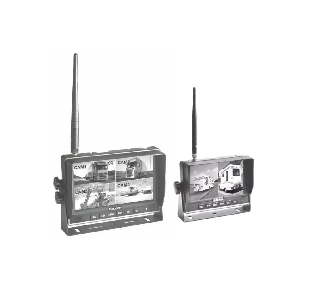
Haloview Handy5 2.4G Digital 720P 5 Inch-7 Inch LCD Wireless Monitor

Precautions

Storage
  1. Do not expose the monitor to extreme heat, cold, or sudden temperature changes. The storage temperature of this device is -30 to+ 80°C or -22 to +176°F . The operating temperature is -20 to+ 70°C or -4 to 158°F with the humidity under RH90%.
  2. Never use this device in environments with excessive moisture, dust or smoke.
  3. Avoid dropping or striking this device.
  4. Never puncture, scratch or use abrasive cleaning materials on this device.
  5. Leave at least a 2″ space between the monitor and walls, cabinets or other objects to allow adequate air circulation around the device.
  6. The monitor is not designed to be waterproof.
Operating Precautions
  1. The device can be powered by a 10 -32 volt automotive battery or vehicle electrical system.
  2. Improper cable connections may damage the monitor. Remove the power cable connections when you do not intend to use the device.

Symbol Warning

  1. High voltage is present within the monitor. The opening of the case should be by professionals.
  2. Do not watch the video while driving unless you are monitoring the rear view camera display.

Symbol Special Notice

Occasionally, a few highlights or dark spots may occur on the LCD screen. This is a very common phenomenon in active matrix display technology, and doesn’t necessarily indicate any defects or faults. Never try to repair this device by yourself. In case of any problems, please turn off the display at once and notify our company or authorized dealer. The monitor is a complex device. Any disassembly or modification may lead to damage and void the warrantee.

Maintenance
  1. Remove all the cable connections from the monitor before cleaning the device.
  2. Use a mild household detergent and clean the unit with a slightly damp, soft cloth. Never use strong solvents such as thinner or benzine, as they might damage the finish of the device.
Symbol

CAUTION

Symbol

RISK OF ELECTRIC SHOCK
DO NOT OPEN

CAUTION: TO REDUCE THE RISK OF ELECTRIC SHOCK
DO NOT REMOVE COVER(OR BACK). NO USER-SERVICEABLE PARTS INSIDE. REFER SERVICING TO QUALIFIED SERVICE PERSONNEL


Symbol This symbol is intended to alert the user to the presence of uninsulated “dangerous voltage” within the product’s enclosure that may be of sufficient magnitude to constitute risk of electric shock to persons.

Symbol This symbol is intended to alert the user to the presence of important operating and maintenance (servicing) instructions in the literature accompanying the appliance.

Declaration of conformity

This device complies with Part 15 of the FCC Rules. Operation is subject to the following two conditions:

  1. This device may not cause harmful interference.
  2. This device must accept any interference received, including interference that may cause undesired operation.
    Symbols

Accessories

  • U-Support Bracket X 1
    Accessories
  • Monitor Suction Cup Mount Bracket X1
    Accessories
  • Sun Shield X 1
    Accessories
  • Metal plate with 3M tape X1
    Accessories
  • Angle Adjustment Screws (5″ x2 / 7″ x4)
    Accessories
  • Cigarette Lighter X1
    Accessories
  • Power Adapter X1
    Accessories
  • BMW connector adaptor X1
    Accessories
  • User Manual X 1
    Accessories

The product is under continuous improvement and the specifications will change without notice. Picture for reference only. Please refer to the actual product and accessories.

Symbol Special Notice

Accessories supplied in kit may be different for each application.

Features

  1. NORMAL, MIRROR, FLIP and MIR-FLIP viewing available.
  2. Split mode, auto-scan mode and single-display mode available.
  3. Auto pairing: Auto pairing happens when camera is activated.
  4. Support 4-channel composite and single-channel recording in AVI signal format.
  5. Auto dim function available.
  6. 4 wireless camera inputs.
  7. Video input: 720P.
  8. Wide voltage input: 10 – 32V.

Specifications

LCD size5″ 16:97″ 16:9
Resolution800 x 3 (RGB) x 4801024 x 3 (RGB) x 600
Contrast1000:1800:1
Brightness800 cd/m2900cd/m 2
Viewing AngleU/D:80, R/L: 80U/D: 85, R/L: 85
Aspect Ratio16:916:9
Channel4 channels4 channels
Operating Frequency2400 – 2483.5 MHz2400 – 2483.5 MHz
Receiving Sensitivity-85 dBm-85 dBm
Video CompressionH.264H.264
Latency200ms200ms
Transmitting Distance984ft line of sight984ft line of sight
Micro-SD /TF CardMax. 128GMax. 128G
Video FormatAVIAVI
Power SupplyDC 10-32VDC 10-32V
Power ConsumptionMax.5.5WMax. 8W
Loudspeaker1W/8O1W/8O
Operating temperature-20-+70°C,RH90%-20-+70°C,RH90%
Storage temperature-30-+80°C,RH90%-30-+80°C,RH90%

Functions of each part

Functions of each part

Basic Operation

  1. Installation of Center Mounting Bracket:
    ①Adjust monitor height by sliding monitor up or down in slot, then tight knob.
    ② Adjust monitor angle by loosening lower knob on center mounting bracket, tilting monitor to desired angle , and re-tighten knob.
    Basic Operation
  2. Installation of U-support Bracket
    Basic Operation
    Basic Operation

Installation

Please find best signal reception position before installation

The metal body of the vehicle can attenuate wireless signal strength sharply. It is necessary to test the signal strength before installation.

  1. Please connect monitor and camera as below picture
    Installation
  2. Pairing the camera to the monitor, please refer to page 18 PAIRING. 4 cameras
    can be paired separately to CAM1/CAM2/CAM3/CAM4.
  3. Put the monitor and the camera at the intended position to test signal strength.
    Installation

If signal strength of the position that you planned to install a camera is under 3 bars, please change to another position, or mount the camera higher to make sure the antenna highest of the top without being blocked. Please refer to below pictures:
Installation

Installation Position 1: Mount the camera higher than your vehicle’s roof, keeping the antenna vertical.

Installation Position 2: Mount the camera lower but as close as possible to vehicle’s roof, and move the antenna outward 15-30 degree. The antennas proximity to any metal surfaces on the vehicle may affect signal strength.

Symbol Special Notice

After position adjustment, you can start installation if your signal strength is still above 3 bars.

Installation

  1. Antennas should be vertically lined to the ground. Make sure there is no obstacle around antennas.
    Installation
  2. Magnet based extension antenna should be attached on the top of the vehicle. Make sure there is no obstacle around.
    Installation

Antenna

Installation

If you get poor signal reception, or signal cannot reach at least 3 bars, please adjust the angle of antenna to find best signal reception position.

Menu

Button Function

Button Function

ButtonFunction
SELSwitch among cameras
ButtonDecrease brightness
MENUEnter menu or return to previous menu
ButtonIncrease brightness
 OKFunction ① : “Start recording”and”pause recording ”
Function ② : “Start playing”and”pause playing”in video playback interface.
Function ③ : Press for 3 seconds to enter pairing status
Function ④ : Press OK button to enter menu item or save user settings.
ButtonTurn on/off monitor and standby

Menu

  1. Press menu button to enter below interface.
    Menu
    Volume
    MENU is only allowed for operation under single image mode, not quad mode. Press MENU to display the following options and settings:
    Volume
  2. Press Button or Button to select VOLUME, Press OK to confirm. Press Button or Button to adjust settings.
  3. Press Button or Button and OK button to set MUTE or UNMUTE.

Picture

  1. Press MENU button to enter menu interface.
  2. Press Button or Button to select PICTURE, Press OK to enter.
    Picture
  3. Press Button or  Button to select BRIGHTNESS/CONTRAST/COLOR, Press OK to confirm. Press Button or Button to adjust settings.

Mirror

  1. Press MENU button to switch to enter menu interface. Press Button or Button to select MIRROR. Press OK button to enter MIRROR setting.
    Mirror
  2. Press Button or Button to select NORMAL/MIRROR/MIR-FLIP/FLIP.

Qmode

  1. Press MENU button to enter menu interface. Press Button or Button and OK button to enter QMODE.
    Qmode
  2. Press Button or Button to select display mode.
  3. After setting, press SEL button to change display mode. For example, If you set QUAD mode” Button
    Pressing SEL button 4 times, the display will switch CAM1 to QUAD.
    Qmode
  4. Quad or Split Audio Setting
    When the monitor display Quad or Split picture, you can press Buttonor Button button to play audio of any of the CAM channel.
    Qmode
Setting
  1. Press MENU button to enter menu interface. Press Button or Button to select SETTING.
    Press OK button to enter SETTING.
  2. SELKEY: User defined CAM switching. For example, if CAM 1, CAM2, Q(QUAD MODE) are selected, When pressing SEL key, the display will switch from CAM1 to CAM2, and QUAD MODE, ii will skip CAM3, CAM4, and SCAN.
  3. Press OK to move selection, press Button or Button key to select or cancel. The bottom yellow dot indicates current selection.
    Setting
    ICONFUNCTION
    IconSet current time. Please make sure your setting is correct, otherwise the time display on recorded videos will be incorrect.
    IconSet video format of the camera. Please refer to below table.
    IconWhen the option is turned “ON”, monitor will automatically decrease brightness in low light. Or you can turn”OFF”the auto-dim function.
    VIDEO FORMATCOUNTRY
    PALArgentina, Australia, Austria, Belgium, Brazil, Bulgaria, China, Cyprus, Czechoslovakia, Denmark, Dubai, Egypt, Finland, France, Germany, Gibraltar, Greece, Hungary, Iceland, India, Indonesia, Ireland, Israel, Italy, Jordan, Kuwait, Luxembourg, Malaysia, Netherlands, New Zealand, Norway, Sultanate of Oman, Poland, Portugal, San Marino, Saudi Arabia, Singapore, Spain, Sweden, Switzerland, Turkey, United Kingdom,
    NTSCBolivia, Canada, Chile, Colombia, Costa Rica, Ecuador, Japan, South Korea, Mexico, United States
  4. Press Buttonor Button and OK button to set TIME/PAL-NTSC/AUTODIM.
Autoscan
  1. Press MENU button to enter menu interface. Press Button or Buttonand OK button to enterAUTOSCAN setting.
    Autoscan
  2. PressButton or Button and OK button to setAUTOSCAN channels and SCANTIME.
  3. Press SEL button to switch to SCAN interface. A SCAN icon will appear on the display. Press again to exit SCAN mode.
    Autoscan
Park-line
  1. Press MENU button to enter menu interface. Press Button or Button and OK button to enter PARK-LINE.
    Display: To set the park line display in a certain channel of CAM. Press Button or Button button to select, press OK button to confirm.
    Park-line
  2. Turn on/off parking lines or enter adjust parking lines setting.
    Park-line
  3. Press Button or Button button to adjust the position of parking lines.
    Park-line
  4. Press Button or Button button to adjust the position of parking lines
    Park-line
  5. Note: Park line display in CAM4 as default, but it is settable if you want it display in other channels of CAM.
Record
  1. Insert TF Card
    Please insert TF card in TF card slot, max 128G Micro-SD/TF Card
    Record
  2. Format the TF card.
    Note: TF card must be formatted before using. Press MENU button to enter menu interface, and enter RECORD setting
    Record
    When COVER is turned on, overwrite function will be activated. Previous recorded video files will be overwritten when TF card memory is full.
    Record
    After TF card formatted, a yellow folder icon will be shown on the screen, indicating TF card is available now.
    Record
  3. After setting, turn on RECORD to start recording or pause recording, or, you can press OK button to start recording or pause recording.
    Record

Note: Pressing OK button in QUAD or SPLIT display, the monitor will record all displayed channel of CAM at the same time.

Play Recorded File

Recorded videos can be played by monitor.

  1. Press Button or Button and OK button to enter PLAY.
  2. Press Button or Button and OK button to select a file.
    Record
  3. PressButton or Button to select TIME& CHANNEL, Press OK to enter.
    Play Recorded File
  4. Press OK button to PLAY or PAUSE the file.
    Play Recorded File
Recording Time

For Micro SD cards with different capacities, please refer to the table below for recording time under 3 different image modes.

This table is for reference only.
Data may vary under different environments.

TFBG16G32G64G128G
MODE
SINGLE (1280x720x1)9H18H36H72H144H
QUAD (512x352x4)10H20H40H80H160H
SPLIT (512x592x2)11H22H44H88H176H
Pairing
  1. Press SEL button to select a channel that needs to be paired.
  2. Monitor Pairing
    Method 1: Enter menu interface and select PARIING, press OK to confirm, you will have 20 seconds for pairing.
    Method 2: Press OK button for 3 seconds to enter PAIRING status, you will have 20 seconds for pairing.
    Pairing
  3. Camera Pairing
    Method 1: Press the pairing button on the back of the camera.
    Method 2: Power off the camera and power on ii again.
    Pairing
  4. Video will be displayed after pairing complete .

Symbol Special Notice

If no picture displayed after pairing, please retry pairing steps and power-on again the camera. The pairing must be completed within 20 seconds, otherwise you need to re-power the camera for pairing.

Troubleshooting

The symptoms described below do not necessarily mean a failure within the display. Please check the following items before you initiate request for repair.

SymptomsPossible Causes/Solutions
No picture No soundImproper connection of automobile adapter. Use of unauthorized power supply.

Power switch is OFF.

Please re-pairing the system. Refer to page 18 PAIRING.

No signalCheck whether the camera is powered on.

Please check whether antennas are plugged on both monitor and camera.

Please check the angle of the antenna.

Please check whether metal obstacles near the antenna. Please re-pairing the system. Refer to page 18 PAIRING.

No soundCheck whether the sound volume is turned off or set too low.
Dark pictureCheck whether brightness and contrast are adjusted correctly.
No colorAdjust the HUE settings.
Button invalidAll Button invalid when trigger wire is activated. Please deactivate trigger wire signal to get the button function valid.

For example, you need to turn off LEFT TURN light or REVERSING light to deactivate trigger wire signal of CAM2 or CAM4. MENU button invalid in split display.

If MENU button invalid, please check whether it is under split display. You need to switch to single display by pressing SEL button to get the MENU button valid.

Unable to recordPlease check whether TF card inserted
Please check whether TF card formatted before recording Please check whether TF card storage full

The monitor is equipped with Anti-Glare screen. Please remove the screen protector to get best picture quality after installation.

Haloview Logo

Documents / Resouces

Download manual
Here you can download full pdf version of manual, it may contain additional safety instructions, warranty information, FCC rules, etc.


Related Manuals