Roco BR 143 DFWK Electric locomotive
Product Information
Product Usage Instructions
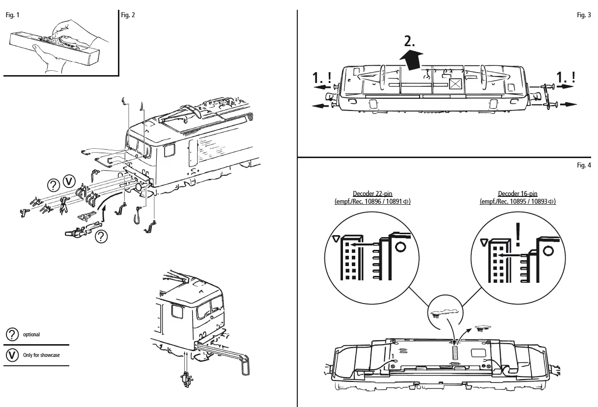
- Unpack the model carefully with the foil (Fig. 1).
- Use the ROCO-Kurzkupplung for optimal running of the model.
- Remove the interface jumper for running the model in digital mode.
- Mount the locomotive kits available in the accessory bag carefully.
- Let the locomotive run for about 30 minutes forwards and 30 minutes backwards without load to obtain an optimal circuit and best tractive power.
- Use Roco track cleaning van or Roco track cleaning rubber (item no. 46400 or item no. 10002) to clean the tracks for smooth running of the locomotive.
Maintenance and care of the model
To ensure the longevity of the model, it is essential to service it regularly (i.e. after it has been in operation for approximately 30 hours).
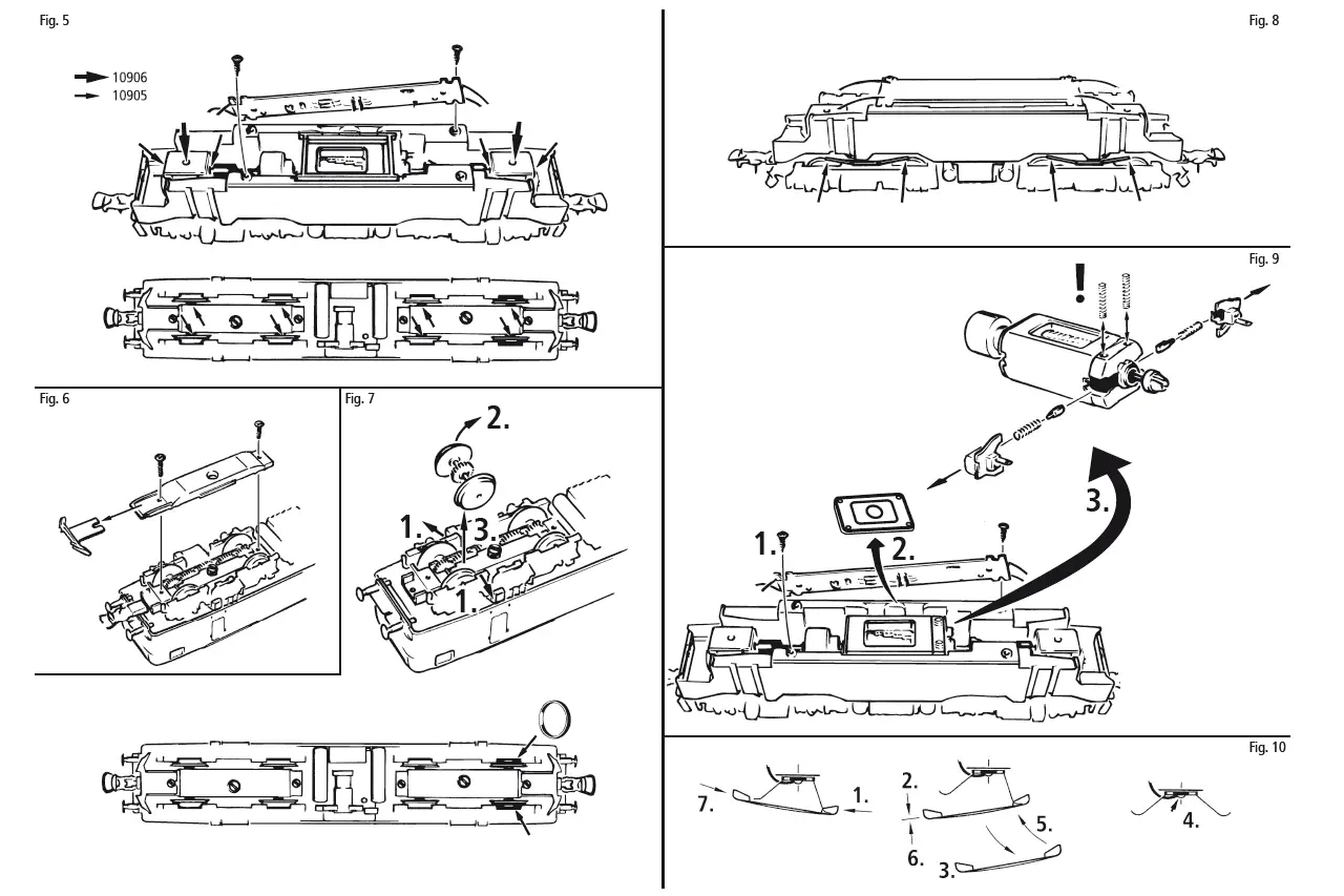
- Clean the wheel contacts with a small brush to remove dirt from spots marked in fig. 8.
- Lubricate the spots marked in fig. 5 with tiny oil drops, dismantle the locomotive prior to lubrication (fig. 3). Use Roco oiler (item no. 10906) for lubrication.
- For lubrication of gear parts such as cogwheels and worm, use Roco special grease (item no. 10905).
- Follow the instructions carefully while changing the Haftreifen and Schiefer of the model.
The latest version of the sound decoder manual can be found on our website under downloads at the article.
Starting locomotive operation
Unwrap model: Take out the model cautiously with foil (fig. 1).
Operating instructions: Before use is advisable to let the loco go around about 30 minutes forwards an 30 minutes backwards without load, to obtain an optomal circuit and best tractive power.
The smallest radius this model should run is R2 of the ROCO track system (R2 = 358 mm).
Your locomotive will run smoothly on clean tracks only. For this purpose we recommend using item no. 46400, Roco track cleaning van, or item no. 10002, Roco track cleaning rubber, for remo-ving heavy dirt.
Fittings: Operation is possible with different couplings (fig. 2). We recommend using the Roco close coupling.In the enclosed accessory bag you will find small kits to be fitted on your locomotive.
Please mount them cautiously.
Attention! Use glue only if indicated (fig. 2).
Running in digital mode:
Remove the jumper from the interface.
Finally put the plug of the chip into the interface as shown in fig. 4.
A.C. pick up: see fig. 10
Maintenance of the model
To enjoy your model for a long time, it is necesary to service it regulary (i.e. after it has been in ope-ration for approximately 30 hours).
- Cleaning of wheel contacts: Wheel contacts easily get dirty on tracks which are not entirely clean. Use a small brush to remove dirt from spots marked in fig. 8.
- Lubrication: Apply tiny oil drops to spots marked in fig. 5. Prior to lubrication dismantle locomotive (fig. 3). We recommend using item no.
10906, Roco oiler. For lubrication the gearparts (e.g. cogwheels, worm) we whould recommended our Roco special grease (item no. 10905). - Change of traction tyre: Remove the bogie blind (fig. 6). Take out wheel set and remove traction tyre using a pin or a fine screwdriver (fig. 7). When pressing on the new traction tyre please avoid twisting it.
- Carbon Brush Changing: First remove loco body (fig. 3), and then the motor (fig. 9).
Assembly: During assembly please take care of correct position of contacts.
Attention: Please do not oil these parts when using our grease.
Decoder interface
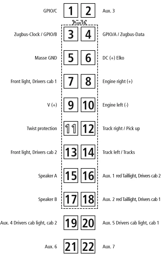
Symbolic Illustration
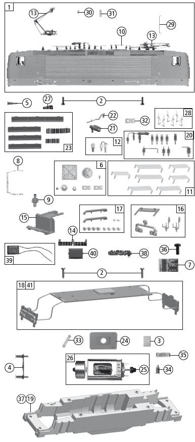
Replacement Parts
| Pos.no. | Description | Art.no. | Price bracket |
| 1 | Body ass. compl. loco no. 143 124-6 | 148708 | 33 |
| 2 | GF-Schraube M2x5 mm GF-Screw | 114966 | 3 |
| 3 | Gummibettung Rubber road bed | 89728 | 4 |
| 4 | Pufferbohle Headstock | 148707 | 4 |
| 5 | Puffer eckig Buffer rectangular | 107419 | 4 |
| 6 | TS – Laufstege, Platten,.. Part set – running boards, plates | 115223 | 11 |
| 7 | Brückenstecker – Plux16 TVS Jumper | 133241 | 10 |
| 8 | Stirnfenster Front window | 148710 | 6 |
| 9 | E-Lokführer E-Loco driver | 110407 | 6 |
| 10 | Hauptleitung Roof wire | 148711 | 8 |
| 11 | Laufstegsatz Part set runningboards | 137882 | 18 |
| 12 | TS – Isolatoren Part set – insulator | 147427 | 7 |
| 13 | Stromabnehmer VSH 3.1 Pantograph | 185312 | 19 |
| 14 | Trittbrett gebogen Running board set bent | 148713 | 6 |
| 15 | Führerstand Drivers cab | 148712 | 5 |
| 16 | TS – Abdeckungen Part set cover | 137877 | 7 |
| 17 | TS – Lichtleiter Part set – light guide | 137880 | 8 |
| 18 | Platine komplett PCB compl. | 137878 | 26 |
| 19 | Grundrahmen Main frame | 137872 | 16 |
| 20 | Isolatorensatz Insulator set | 113433 | 9 |
| 21 | Hauptschalter Main switch | 148715 | 4 |
| 22 | Leitung Wire | 148716 | 7 |
| 23 | TS-Düsen+Mittelüfter Part set-nozzle+middle vents | 100242 | 9 |
| 24 | Distanzplättchen Spacer | 105764 | 3 |
| 25 | Kardanschale Cardan bearing | 87129 | 4 |
| 26 | Motor Motor | 85086 | 28 |
| 27 | UIC-Dose UIC-socket | 111407 | 3 |
| 28 | TS-Scheibenwischer TS-Windscreen wipers | 137994 | 11 |
| 29 | Türgriffstange lackiert Door handrail coated | 148714 | 4 |
| 30 | Antenne Antena | 107429 | 3 |
| 31 | Zugfunkantenne Radio antenna | 137885 | 3 |
| 32 | Platte 7,9×4 mm Plate | 107432 | 3 |
| 33 | Motor Kontaktfeder D=2,4 L=11,6 mm Motor contact spring | 116876 | 3 |
| 34 | Kohlebürste Carbon brush spring | 89743 | 6 |
| 35 | Bürstenfeder Carbon brush spring | 114197 | 3 |
| 36 | GF-Schraube M2x4 mm Self-tapping screw | 114877 | 3 |
| AC-Wechselstrom | |||
| 37 | Grundrahmen Main frame | 138044 | 16 |
| Sound | |||
| 38 | Sounddecoder Sound decoder | 148719 | 40 |
| 39 | Lautsprecher Loudspeaker | 129524 | 13 |
| 40 | Lautsprecherbox Loudspeaker box | 134067 | 5 |
| 41 | Platine kpl. mit LED-Platine + Sound Printed circuit ass. witk LED-pr. circuit + sound | 137998 | 29 |
We reserve the right to change the construction and specification
Symbolic Illustration
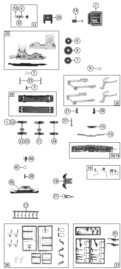
Replacement Parts
| Pos. Nr. Pos.no. |
Beschreibung Description | Art.-Nr. Art.no. | Preisgruppe Price bracket |
| 1 | Haftrings.10Stk.12,9-14,6mm Traction tyre set 10 part 12,9-14,6mm | 40070 | — |
| 2 | Mittelkasten Middle box | 148706 | 11 |
| 3 | FK-Schraube m.Gew. M2X4,5/7,5 FK-Screw | 85771 | 4 |
| 4 | Beilagscheibe 2.1X4/0.2 MM Washer | 86108 | 3 |
| 5 | Feder Spring | 86202 | 3 |
| 6 | Schneckenzahnrad doppelt Worm gear double | 86419 | 6 |
| 7 | Zahnrad Z=23 gerade M 0.4 Gearwheel | 111679 | 3 |
| 8 | Zahnrad Z=29/M-0.4 Gearwheel | 86467 | 3 |
| 9 | Zugfeder Draw spring | 86208 | 3 |
| 10 | Lager für Schneckenachse Bearimg for worm axle | 89749 | 6 |
| 11 | Radsatz m. Zahnrad o. Haftringe Wheelset w. gearwh. w/o traction tyres | 90828 | 11 |
| 12 | Schneckensatz Worm set | 100254 | 13 |
| 13 | Radkontakt Wheel contact | 100256 | 3 |
| 14 | Kardanwelle Cardan shaft | 100260 | 4 |
| 15 | Kontakthalter Contact holder | 100485 | 3 |
| 16 | Schienenräumer Rail guard | 148705 | 4 |
| 17 | Attrappenrahmen klein/schwarz Push in part set, small | 107808 | 4 |
| 18 | TS-Lagerdeckel+Treppensatz Part set-Bogiecover+stairset | 148703 | 6 |
| 19 | Blende komplett 1 Boogie frame assembly | 148701 | 18 |
| 20 | Schneckendeckel Wormcover | 94707 | 4 |
| 21 | Standardkupplung Standard coupling | 89246 | 6 |
| 22 | Radsatz mit Zahnrad mit 2 Haftringen Wheelset w. gearwheel w. 2 traction tyres | 107423 | 12 |
| 23 | Zurüstbeutel Bag w. accessories | 107436 | 15 |
| 24 | Getriebe kpl. Gear ass.compl. | 137874 | 13 |
| 25 | GF-Schraube M2X6 mm GF-Screw | 114828 | 3 |
| 26 | Zurüstbeutel Bag with accessories | 148717 | 14 |
| 27 | SK-Schraube M1,6×4 mm SK-screw | 115161 | 3 |
| 28 | GF-Schraube M1,6×5 mm GF-screw | 115269 | 3 |
| 29 | Blende 2 kpl. mit Litzen Bogie 2 ass. with wires | 148702 | 18 |
| 30 | TS – Kinematik Part set – kinematics | 137876 | 7 |
| 31 | Kurzkupplung Vor-entkupplung Short coupling pre-uncoupling | 115550 | 6 |
| 32 | Schnecke Wormgear | 86704 | 6 |
| AC-Wechselstrom | |||
| 33 | Haftrings.10Stk.12,5-15,3mm Set with traction tires 10 pieces | 40075 | — |
| 34 | Radsatz ohne Zahnrad/ohne Haftring AC Wheelset without gear/without traction tyres | 90830 | 10 |
| 35 | Radsatz mit Haftringen Wheelset with traction tyres | 90831 | 12 |
| 36 | Schleifer 46 mm Slider | 86031 | 14 |
| 37 | GF-Schraube M2x5 mm GF-Screw | 114966 | 3 |
| 38 | GF-Schraube M1,6×5 mm GF-Screw | 115269 | 3 |
| 39 | Getriebesatz 2tlg Gear set – 2 parts | 137999 | 10 |
| 40 | Anschlußnippel M 1,6 mm Connection nippel | 111116 | 4 |
| 41 | Scheibe Washer | 112681 | 3 |
Spare parts can be ordered directly at www.roco.cc and from your local dealer.
The values for CV (DCC) or Register (Motorola) showing in the table are only obtained for the Sounddecoder of the “BR 143 / BR 243 / BR 112“.
The Sounddecoder was optimized for this locomotive. However, many of the decoder properties can be adjusted to meet your specific needs. Certain parameters (the so-called configuration variables [CVs] or registers) are used for this purpose. Please consult the chapter “Adjustment Options with DCC Digital Mode“ and „Adjustment Options with Motorola Digital Mode“ of the included Sounddecoder operating manual for further details. Before starting any type of programming, please make sure that this action is really necessary. Wrong settings may cause the decoder to respond incorrectly.
The decoder is factory-set to 28 running steps for optimal traveling comfort. This means the decoder can be used with all modern DCC (e.g. Z21,MULTIMAUS and Lokmaus 2) as well as Motorola control units. The latest version of the sounddecoder manual can be found on our website under downloads at the article.
Note: The running sound can be triggered with the horn button when using the decoder with Lokmaus 1 systems. However, the decoder must be reset to 14 running steps in order for the light function to work properly. Please consult the Lokmaus manuals for further details or contact your retailer.
A stronger link between driving and sound sequences is available in the case of this newest generation sound decoder: therefore the engine will not start to move correspondingly when the sound model is switched on (‘F1’ function key activated) until the ‘placing in service’ sound sequence is completely closed and ‘in running order’ status has been reached. Conversely, the ‘placing out of service’ sound sequence will then only run and subsequently convert to the ‘placed out of service’ status, following the operation of the ‘F1’ function key (now: ‘Sound Off’) again, if the engine had already stopped when the ‘F1’ key was operated. Therefore, switching the sound on or off quickly by means of the ‘F1’ key will only be possible if the engine is already or still in movement. The momentary or longterm (= ‘Sounding Through’) activation of the signal of the engine will take place exclusively by switching on the function, because the programming of the function has been designed as a switch (‘on/off’), not as a key (key pressed = function triggered: key released = function off); this is necessary as a ‘sounding through signal’ in the case of certain engine sounds. This means that a second signal sound can only be triggered after the second operation of the function.
The whole sequence of the function is:
- 1st switch pressure = signal tone one, 2nd switch pressure = signal tone off,
- 3rd switch pressure = signal tone on, 4th switch pressure = signal tone off, etc.
Factory programmed address: format «DCC» du NMRA / Motorola: 03
| F0 | Light on/off |
| F1 | Driving noise |
| F2 | Horn |
| F3 | Horn |
| F4 | Conductor‘s signal |
| F5 | Single locomotive journey: The F5 key can be used to select an alternative engine sound |
| F6 | Shunting light |
| F7 | Compressor |
| F8 | Carriage light deactivation from driver’s cab 2 |
| F9 | Carriage light deactivation from driver‘s cab 1 |
| F10 | Driver’s cabin light (according to direction of travel) |
| F11 | Decouple |
| F12 | Couple |
| F13 | Horn |
| F14 | Mute key |
| F15 | Pressure relief valve |
| F16 | Station announcement |
| F17 | Points rattling (only if F1 is switched on and the Locomotive drives) |
| F18 | Shunter |
| F19 | Volume decrease |
| F20 | Volume increase |
| F21 | Sanding |
| F22 | Check PZB |
| F23 | Deactivation of the acceleration and braking delay (CV3 and CV4) |
Procedure: Press F5 when the vehicle is stationary (when the idling noise is being played). Now, the locomotive will remain in idling mode up to a model speed of approx. 30 km/h, as is usual in the event of an individual locomotive journey. As a towing locomotive, F5 must be switched off again in the same manner. (Note: F1 must be switched on. The F23 function is automatically deactivated when the F5 function is active.)
| CV | Default setting | CV | Default setting |
| 1 | 3 | 6 | 80 |
| 2 | 8 | 8 | 8 = Reset |
| 3 | 36 | 29 | 14 |
| 4 | 20 | 266 | 70 |
| 5 | 190 |
More information about the sounddecoder can be found here:
Modelleisenbahn GmbH
A-5101 Bergheim
Plainbachstraße 4
Email: [email protected]
Tel.: 00800 5762 6000
(kostenlos/ free of charge/ gratuit)
International: +43 820 200 668


