![]()
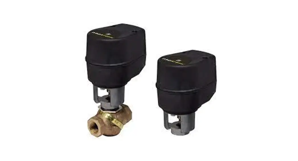
AT080-30 Actuator
Actuator Specification
Instruction Manual
AT080-30 Actuator
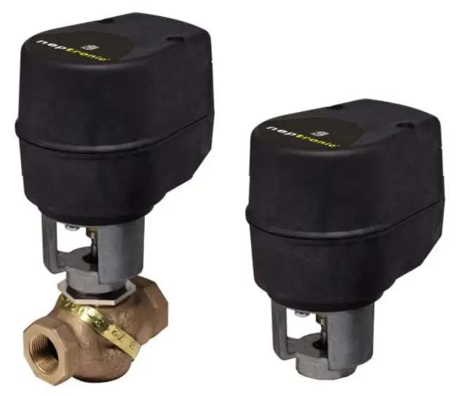 Feature:
| • Variable running time. | AT000 |
| • Manuel override. | AT020 |
| • Maintenance free. | AT060 |
| • Fail safe by Enerdrive System (on models 060 & 080). | AT080 |
| • Auxiliary switches. (on models 020 & 080). | AT000-30 |
| AT020-30 | |
| AT060-30 | |
| AT080-30 |
| Technical Data | AT000 | AT020 | AT060 | AT080 | AT000-30 | AT020-30 | AT060-30 | AT080-30 |
| Auxiliary switches | No | Yes(2) | No | Yes(2) | No | Yes(2) | No | Yes(2) |
| Feedback | No | No | No | No | No | No | No | No |
| Fail safe – Enerdrive | No | Yes | No | Yes | ||||
| Power consumption | 6 VA | 20VA Peak, 6VA | 6 VA | 20VA Peak, 6VA | ||||
| Control signal | 3 wire / 2 position, 3 wire / 3 point floating | 2 wire / 2 position. 4 wire / 3 point floating | 3 wire / 2 position. 3 wire / 3 point floating | 2 wire / 2 position. 4 wire / 3 point floating | ||||
| Running time | 60 sec force dependant | 30 sec force dependant | ||||||
| Force | 100 lb. [450 N] at rated voltage | |||||||
| Power supply | 22 to 26 VAC or 28 to 32 VDC | |||||||
| Electrical connection | 18 AWG [0.8 mm2] minimum | |||||||
| Inlet bushing | 2 inlet bushing of 5/8 in [15.9 mm] & 7/8 in [22.2 mm] | |||||||
| Maximum Stroke | 0.5 in [12.7mm] | |||||||
| Direction | Reversible. normally open or normally close (factory set with normally close direction) | |||||||
| Ambient temperature | 0°F to +122°F [-18°C to +50°C] | |||||||
| Storage temperature | -22°F to +122°F [-30°C to +50°C] | |||||||
| Relative Humidity | 5 to 95 % non condensing. | |||||||
| Weight | 2 lbs. [0.9 kg] | |||||||
| Warning: Do not use automatic screw driver on manual override | ||||||||
Dimensions 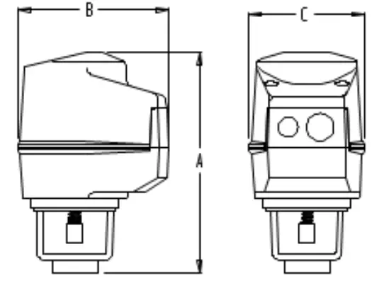
| Dimension | Inches | Metric (mm) |
| A | 5.93 | 150.6 |
| B | 4.8 | 121.9 |
| C | 3.6 | 91.4 |
Caution
We strongly recommend that all neptronic® products be wired to a separate transformer and that transformer shall service only neptronic® products. This precaution will prevent interference with, and/or possible damage to incompatible equipment.
When multiple actuators are wired on a single transformer, polarity must be observed. Long wiring runs create voltage drop which may affect the actuator performance.
AT000/020/060/080
AT000-30/020-30/060-30/080-30
Mechanical installation
Mounting of the actuator on valve
Correct mounting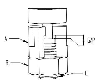 | Non Correct mounting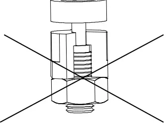 | 1. Screw completely the valve shaft (C) unto the coupling of the actuator (A). 2. Unscrew the coupling (A) for ½ of turn in order to leave a functional play. 3. Screw the counter nut (B). Warning: Do not over tight coupling of the actuator on the shaft of the valve. |
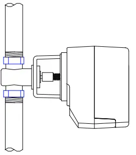
Mounting of the actuated valve on system
| Vertical mounting
| Horizontal mounting
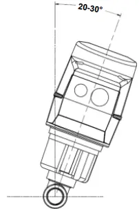
| 1. Pay attention to system particularity; be sure that the expansions, contractions of the system and its medium as well as operating pressures are within the tolerances. 2. When plumbing, the motorized valve should be situated in an easily accessible place and sufficient space should be allowed for the removal of the actuator. 3. To prevent moisture from collecting in the motor casing, install the motorized valve such that the actuator is superior to the valve, at 20-30º / at vertical. Avoid mounting the valve so that the valve stem is below horizontal. |
Wiring Diagrams
| Models AT000 & 020 AT000-30 & 020-30 | Models AT060 & 080 AT060-30 & 080-30 |
3 wire / 2 position (ON-OFF)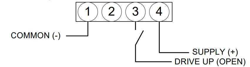 | 2 wire / 2 position (ON-OFF)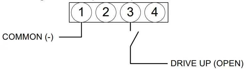 |
3 wire / 3 point floating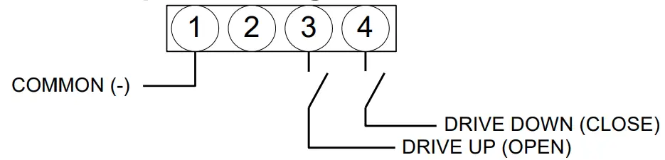 | 4 wire / 3 point floating |
PC Board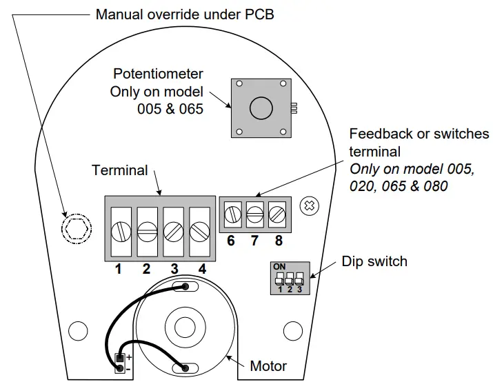 | Dip switch settings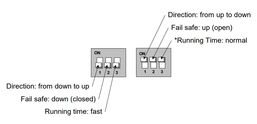 |
*On AT model:
When switch #3 is “ON”, the running time will be 60 sec. ![]()
LISTED TEMPERATURE REGULATING EQUIPMENT 41 X 9
CLASS 2 CIRCUIT


