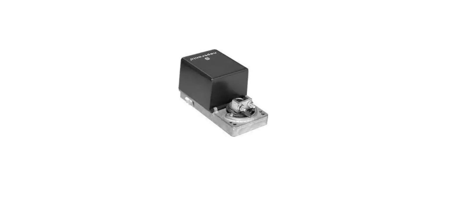
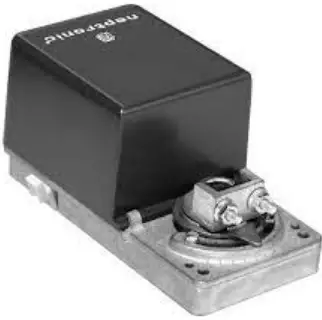
neptronic WM110 Actuator
Features
- Up to 4000 in.lb [450Nm].
- Clutch for manual adjustments.
- Maintenance free.
- Control signal fully programmable.
- Fail safe (battery backup) (on model 110 & 130).
- Auxiliary switches (on model 120 & 130).
- IP56 enclosure.
| Technical Data | UM100 | UM120 | UM110 | UM130 | WM100 | WM110 |
| Auxiliary switches | No | Yes (2) | No | Yes (2) | No | |
| Fail safe | No | Yes | No | Yes | ||
| Torque | 2500 in.lb. [280 Nm] at rated voltage | 4000 in.lb. [450 Nm] at rated voltage | ||||
| Running time through 90º | 4 min. | 8 min. | ||||
| Feedback | 4 to 20 mA or 2 to 10 VDC adjustable | |||||
| Power consumption | 40 VA | |||||
| Power supply | 28 to 32 VDC or 22 to 26 VAC, 110 to 130 VAC 50/60Hz | |||||
| Electrical connection | 18 AWG [0.8 mm2] minimum | |||||
| Inlet bushing | 3 inlet bushing of 7/8 in [22.2 mm] | |||||
| Control signal | Analog or Digital or PWM programmable (factory set with Analog control signal) | |||||
| Angle of rotation | 0 to 110 degrees, electronically adjustable (factory set with 110º stroke) | |||||
| Direction of rotation | Reversible, Clockwise (CW) or Counterclockwise (CCW) (factory set with CW direction) | |||||
| Ambient temperature | 0ºF to +122ºF [-18º C to +50º C] | |||||
| Storage temperature | -22ºF to +122ºF [-30º C to +50º C] | |||||
| Relative Humidity | 5 to 95 % non condensing. | |||||
| Weight | 29 lbs. [13 kg] | |||||
| Warning: Do not press the clutch when actuator is powered | ||||||
Dimensions
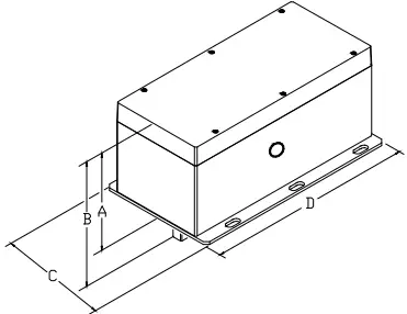
| Dimension | Inches | Metric (mm) |
| A | 6.75 | 169.4 |
| B | 7.95 | 201.9 |
| C | 7.85 | 199.4 |
| D | 14.45 | 367.0 |
Caution
We strongly recommend that all Neptronic products be wired to a separate transformer and that transformer shall service only Neptronic products. This precaution will prevent interference with, and/or possible damage to incompatible equipment. When multiple actuators are wired on a single transformer, polarity must be observed. Long wiring runs create voltage drop which may affect the actuator performance.
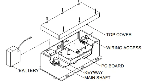
Exploded view
Wiring Diagrams
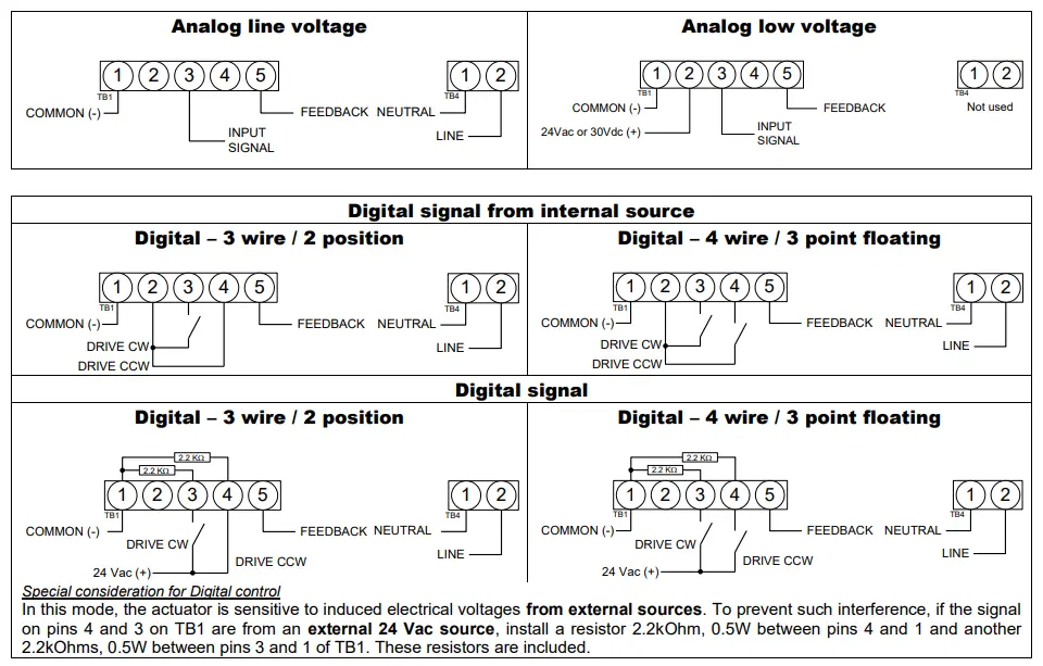
Input Signal and Feedback setup
PC Board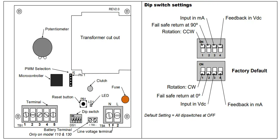
Stroke adjustment – No control signal change
- Apply power and, wait for at least 10 seconds.
- Press and release the reset button to start the auto-stroke process.
The LED should be illuminated.- First option:
The actuator will then travel in both directions to find its limit and position itself according to the demand. The LED will extinguish, the process is complete. - Second option:
When the desired end position is reached, press and release the reset button. The actuator will now return back to its original position. (you can also press and release the reset button when It’s reaches the original position)The LED will extinguish, the process is complete.
- First option:
Programming – Change of control signal & PWM pulse setting
- Remove power and put all dip switches “OFF”. (factory preset).
- Apply power and, within 10 seconds, press and release the reset button. The LED should be blinking.
- Select the control signal with dip switches:
| Digital or Analog Modes | PWM Mode | |
| Move switch No1 “ON” and then “OFF”. | Digital (On/Off or 3 point floating) | 5 sec. pulse (factory preset) |
| Move switch No2 “ON” and then “OFF”. | Analog (Default) | 25 sec. pulse |
For stroke, adjustment
- see the stroke adjustment section above.
Enabling or disabling PWM mode
- Remove the power supply to the actuator
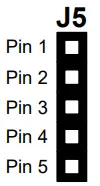
- Install a jumper between pin 3 & 4 of J5
- Select the desired action using the dipswitches (DS1):
DS1-1 DS1-2 Action OFF ON Enable PWM Mode ON OFF Disable PWM Mode - Re-apply power supply to actuator
- Wait 5 seconds
- Remove power supply to actuator
- Remove jumper between pin 3 & 4 of J5, re-install it between pin 4 & 5.
- Re-apply power supply to actuator
PWM is factory preset at 5 sec. pulse, refer to programming section above to change pulse setting.
Zero and span calibration
This feature is applicable to analog control signal only.
- Remove power and put all dip switches “OFF”. (factory preset).
- Apply power and, within 10 seconds press and hold the reset button until the LED blinks. The Zero and span calibration process then start.
- Release the reset button. The LED is now constantly illuminated.
- Apply new minimum voltage. It can be any value between 0 to 7 VDC, with an external 0 to 10 volt supply (ex: MEP).
- Press and release the reset button to memorize the new minimum voltage. The LED blinks.
- Apply new maximum voltage. It can be any value between 3 to 10 VDC, this value should be greater than the new minimum value.
- Press and release the reset button to memorize the new maximum voltage. The LED blinks. The Zero and span calibration process is complete.
Note: To reset zero and span to 2 to 10 VDC (factory value). You just have to re-select the analog control signal mode, see Programming.
Wiring Diagrams for auxiliary switches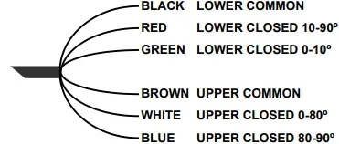
Auxiliary switch rating:
5 Amp resistive, 250 Vac


