![]() Actuator
Actuator
Specification & Installation Instructions 
TM100FN Fast Actuator
TM100FN, TM120FN, TM160FN, TM180FN, RM100FN, RM120FN, RM160FN, RM180FN
Features:
- Clutch for manual adjustments.
- Maintenance free.
- Position indicator.
- Control signal fully programmable.
- Brushless DC driven motor.
- Fail safe by Enerdrive System¹ (on model 160 & 180).
- Auxiliary switches (on model 120 & 180).
Technical Data
| TM100FN | TM120FN | TM160FN | TM180FN | RM100FN | RM120FN | RM160FN | RM180FN | ||
| Auxiliary switches | No | Yes (2) | No | Yes (2) | No | Yes (2) | No | Yes (2) | |
| Fail safe – Enerdrive | No | No | Yes | Yes | No | No | Yes | Yes | |
| Power consumption | 30 VA | 50 VA Peak, 30 VA | 30 VA | 50 VA Peak, 30 VA | |||||
| Torque | 120 in.lb. [13.5 Nm] at rated voltage | 240 in.lb. [27 Nm] at rated voltage | |||||||
| Running time through 90° | 20 sec torque dependant | ||||||||
| Power supply | 28 to 32 Vdc or 22 to 26 Vac, 110 to 130 Vac 50/60Hz | ||||||||
| Feedback | 4 to 20 mA or 2 to 10 Vdc adjustable | ||||||||
| Electrical connection | 18 AWG [0.8 mm2] minimum | ||||||||
| Inlet bushing | 2 inlet bushing of 7/8 in [22.2 mm] | ||||||||
| Control signal | Analog, Digital or PWM programmable (factory set with analog control signal) | ||||||||
| Angle of rotation | 0 to 90 degrees, electronically adjustable (factory set with 90° stroke) | ||||||||
| Direction of rotation | Reversible, Clockwise (CW) or Counterclockwise (CCW) (factory set with CW direction) | ||||||||
| Operating temperature | 0°F to 122°F [-18°C to 50°C] | ||||||||
| Storage temperature | -22°F to 122°F [-30°C to 50°C] | ||||||||
| Relative Humidity | 5 to 95 % non condensing. | ||||||||
| Weight | 5 lbs. [2.3 kg] | 8 lbs. [3.5 kg] | |||||||
| Warning: Do not press the clutch when actuator is powered | |||||||||
Dimensions
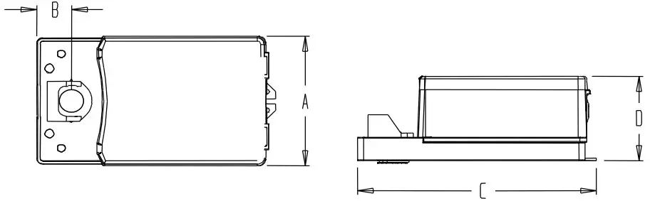
| Dimension | Imperial (in) | Metric (mm) |
| A | 5.2 | 132.1 |
| B | 1.33 | 33.8 |
| C | 9.13 | 231.9 |
| D | 3.55 | 90.2 |
Caution
We strongly recommend that all Neptronic® products be wired to a separate transformer and that transformer shall service only Neptronic® products. This precaution will prevent interference with, and/or possible damage to incompatible equipment.
When multiple actuators are wired on a single transformer, polarity must be observed. Long wiring runs create voltage drop which may affect the actuator performance.
TM100/120/160/180FN
RM100/120/160/180FN
Mechanical Installation
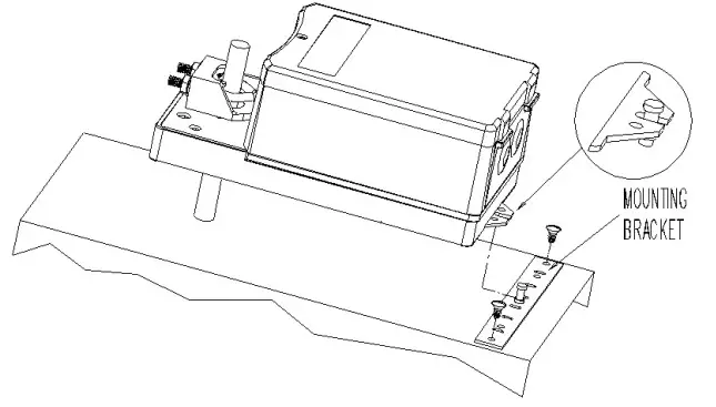
- Manually close the damper blades and positioned the actuator at 0º or 90º.
- Slide the actuator onto the shaft.
- Tighten the nuts on the “U” bolt to the shaft with a 10mm wrench to a torque of 150 in.lb. [17 Nm].
- Slide the mounting bracket under the actuator. Ensure free movement of the slot at the base of the actuator. The bracket pin must be placed in the mid distance of the slot.
- Fix the bracket to the ductwork with #8 self-tapping screws.
Wiring Diagrams
| Analog line voltage | Analog low voltage |
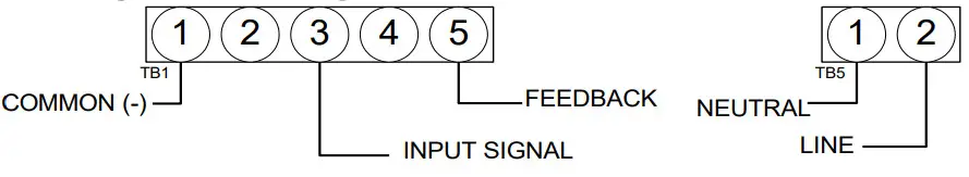 | 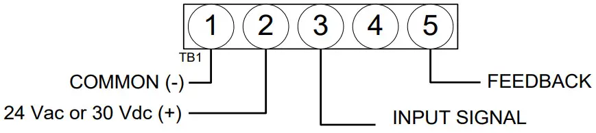 |
Digital signal from internal source
| Digital – 3 wire / 2 position | Digital – 4 wire / 3 point floating |
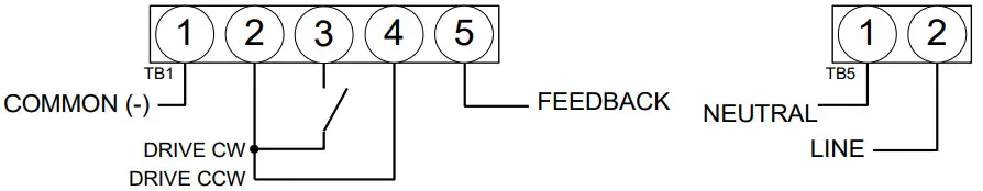 | 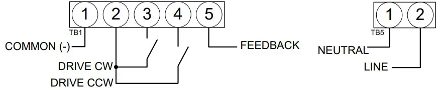 |
Digital signal from external 24 Vac source
| Digital – 3 wire / 2 position | Digital – 4 wire / 3 point floating |
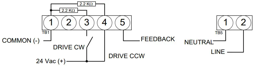 | 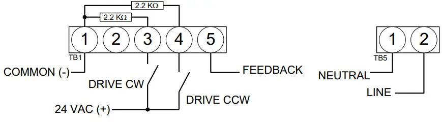 |
Special consideration for Digital control
In this mode, the actuator is sensitive to induced electrical voltages from external sources. To prevent such interference, if the signal on pins 4 and 3 on TB1 are from an external 24 Vac source, install a resistor 2.2kohm, 0.5W between pins 4 and 1 and another of 2.2kohms, 0.5W between pins 3 and 1 of TB1. These resistors are included.
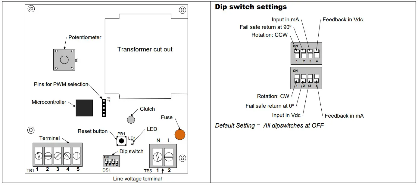
Input Signal and Feedback setup
| Input Signal | Feedback | |
| Analog Mode | Input Signal is set with Dipswitch # 3 DS1-3 at OFF = 2 – 10Vdc (default setting) DS1-3 at ON = 4 – 20mA | Feedback is set with Dipswitch #4 DS1-4 at OFF = 4 – 20mA (default setting) DS1-4 at ON = 2 – 10Vdc |
| Digital Mode & PWM Mode | No Input Signal Setting |
TM100/120/160/180FN
RM100/120/160/180FN
PC Board
 Stroke adjustment – No control signal change
- Apply power and, WAIT FOR LED TO BE OFF (around 10 seconds).
- Press and release the reset button to start the auto-stroke process.
The LED should be illuminated.
• First option:
The actuator will then travel in both directions to find its limit and position itself according to the demand.
The LED will extinguish, the process is complete.
• Second option:
When the desired start position is reached, press and release the reset button. The actuator will now go the end position. (you can also press and release the reset button when It’s reaches the end position) The LED will extinguish, the process is complete.
Programming – Change of control signal & PWM pulse setting
- Remove power and put all dip switches “OFF”. (factory preset).
- Apply power and, within 10 seconds, press and release the reset button. The LED should be blinking.
- Select the control signal with dip switches:
• Digital (On/Off or 3 point floating) move switch No1 “ON” and then “OFF”.
• Analog (factory preset) move switch No2 “ON” and then “OFF”.Digital or Analog Modes PWM Mode Move switch No1 “ON” and then “OFF”. Digital (On/Off or 3 point floating) 5 sec. pulse (factory preset) Move switch No2 “ON” and then “OFF”. Analog (Default) 25 sec. pulse - Stroke adjustment
see the stroke adjustment section above.
TM100/120/160/180FN
RM100/120/160/180FN
Enabling or disabling PWM mode
- Remove power supply to actuator
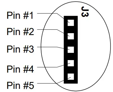
- Install jumper between pin 3 & 4 of J3
- Select the desired action using the dipswitches (DS1):
DS1-1 DS1-2 Action OFF ON Enable PWM Mode ON OFF Disable PWM Mode - Re-apply power supply to actuator
- Wait 5 seconds
- Remove power supply to actuator
- Remove jumper between pin 3 & 4 of J3, re-install it between pin 4 & 5.
- Re-apply power supply to actuator
PWM is factory preset at 5 sec. pulse, refer to programming section above to change pulse setting.
Zero and span calibration
This feature is applicable to analog control signal only.
- Remove power and put all dip switches “OFF”. (factory preset).
- Apply power and, within 10 seconds press and hold the reset button until the LED blinks once.
The Zero and span calibration process then start. - Release the reset button. The LED is now constantly illuminated.
- Apply new minimum voltage.
It can be any value between 0 to 7 Vdc, with an external 0 to 10 volt supply (ex: MEP). - Press and release the reset button to memorize the new minimum voltage. The LED blinks.
- Apply new maximum voltage.
It can be any value between 3 to 10 Vdc, this value should be greater than the new minimum value. - Press and release the reset button to memorize the new maximum voltage. The LED blinks.
The Zero and span calibration process is complete.
Note: To reset zero and span to 2 to 10 Vdc (factory value). You just have to re-select the analog control signal mode, see Programming.
Wiring Diagrams for auxiliary switches (on model 120 & 180) 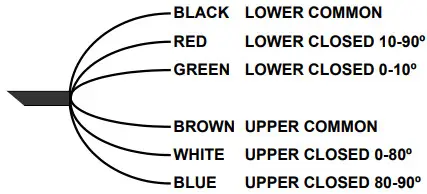 Auxiliary switch rating: 5 Amp resistive, 250 Vac
¹Enerdrive System U.S.A. Patent #5,278,454
TM1FN-RM1FN_210804![]()


