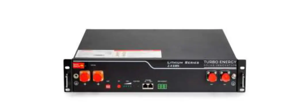
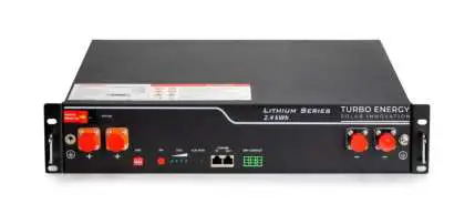
TURBO ENERGY SOLAR INNOVATION US2000C Lithium Series 48V 2.4 kWh Battery
Scope
This document describes the basic operation of the Turbo Energy brand lithium-ion rechargeable battery (Lithium Series 48V 2.4 kWh model). This manual contains all the necessary details for understanding the operation of the equipment and for its correct application.
Specifications
Electrical
| Nominal Energy | 2.4 kWh |
| Nominal Capacity | 50Ah |
| Depth of Discharge (DoD) | 90% |
| Nominal Voltage | 48V |
| Voltage operating range | 40.5 – 54V |
| Cycle Life | >= 6000 |
Physical
- Weight 22 kg
- Dimensions 480 x 360 x 90 mm
- Protection class IP20
- Battery type LiFePO4
Operation
| Charge/discharge current | 25A (0.5 C) |
| Max. Charge current | 45A |
| Max. Discharge current | 55A |
| Temperature operating range (charge) | 0ºC…50ºC |
| Temperature operating range (discharge) | -20ºC…50ºC |
| Humidity | 5%…85% |
| Max. operating altitude | < 4000 m |
BMS
- Monitoring parameters
System voltage, Cell voltaje, current and temperature - Communication Compatible CAN and RS-485
Features
The Lithium Series 48V 2.4 kWh battery has the following features:
- Designed for use in photovoltaic applications.
- Battery Management System (BMS): The BMS system built into the battery that monitors its operation and does not allow it to work outside the bounds of the design regime (V, I).
- Expandability: The system’s accumulation capacity can be expanded by incorporating more batteries.
Operation
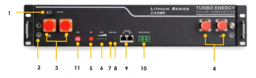
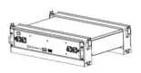
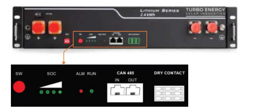
Battery front
| Item | Name | Definition |
| 1 | Power switch | OFF/ON, must be in the “ON” state when in use |
| 2 | Ground connection point | Shell ground connection |
| 3 | Positive socket | Battery output positive or parallel positive line |
| 4 | Negative socket | Battery output negative or parallel negative line |
| 5 | SW (battery wake/sleep switch) | When the “OFF/ON” switch button is in the ON state, press and hold this button for 3 seconds to put the battery into the power-on or sleep state. |
| 6 | SOC | The number of green lights on shows the remaining battery power. See table below for details. |
| 7 | ALM | Red light flashing when an alarm occurs, red light always on during protection status. After the condition of trigger protection is released, it can be automatically closed. |
| 8 | RUN | Green light flashing during standby and charging mode. Green light always on when discharging. |
| 9 | CAN/485 | Communication cascade port, support CAN/ RS485 communication (factory default CAN communication) |
| 10 | DRY CONTACT | / |
| 11 | ADD | DIP switch |
| Battery Status | SOC | LED1 | LED2 | LED3 | LED4 | ALM | RUN |
| Shutdown | / | off | off | off | off | off | off |
|
Standby | 75%≤SOC≤100% | ● | ● | ● | ● | off | Flashing |
| 50%≤SOC<75% | ● | ● | ● | off | off | Flashing | |
| 25%≤SOC<50% | ● | ● | off | off | off | Flashing | |
| 5%<SOC<25% | ● | off | off | off | off | Flashing | |
| 0%<SOC≤5% | ● | off | off | off | Flashing | Flashing | |
| SOC=0 | off | off | off | off | Flashing/● | Flashing | |
|
Charging | SOC=100% | ● | ● | ● | ● | off | Flashing |
| 75%≤SOC< 100% | ● | ● | ● | Flashing | off | Flashing | |
| 50%≤SOC<75% | ● | ● | Flashing | off | off | Flashing | |
| 25%≤SOC<50% | ● | Flashing | off | off | off | Flashing | |
| 0%<SOC<25% | Flashing | off | off | off | off | Flashing | |
|
Discharging | 75%≤SOC≤100% | ● | ● | ● | ● | off | ● |
| 50%≤SOC<75% | ● | ● | ● | off | off | ● | |
| 25%≤SOC<50% | ● | ● | off | off | off | ● |
Battery Management System (BMS)
Voltage Protection
Low Voltage Protection in Discharging:
When any battery cell voltage or total voltage is lower than the protection value during discharging, the over-discharging mode is activated, and the battery buzzer makes an alarm sound. Then battery system stops supplying power to the outside. When the voltage of each cell back to rated range, the protection is over.
Over Voltage Protection in Charging:
Battery will stops charging when total voltage or any battery cell voltage reaches the rated protection value during charging stage. When total voltage or all cell back to rated range, the protection is over.
Current Protection
Over Current Protection in Charging:
When the charge current >45A, current limit protection mode is activated, current will be limited to 5A,protection is removed after rated time delaying 10S. Circulate like this until the current is lower than 45A.
Over Current Protection in Discharging:
When the discharging current is greater than the protection value 55A, the battery buzzer alarms and the system stops discharging. Protection is removed after rated time delaying 1min.
Caution: The buzzer sound alarm setting can be manually turned off on the background software, and the factory default is on.
Temperature Protection
Low/Over temperature protection in charging:
When battery’s temperature is beyond range of -5℃~+55℃during charging,
temperature protection is activated, device stops charging.
The protection is over when temperature back to rated working range.
Low/Over temperature protection in discharging:
When battery’s temperature is beyond range of -20℃~+55℃ during discharging, temperature protection is activated, device stops supplying power to the outside.
The protection is over when temperature back to rated working range.
Other Protection
Short Circuit Protection:
When the battery is activated from the shutdown state, if a short circuit occurs, the system starts short-circuit protection for 60 seconds.
Self-Shutdown:
When device connects no external loads and power supply and no external communication for over 72 hours, device will dormant standby automatically.
Caution
Battery’s maximum discharging current should be more than load’s maximum working current.
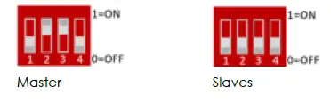
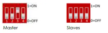
DIP switch
When the batteries are connected in parallel, the host communicates with the slaves through the CAN interface. The host summarizes the information of the entire battery system and communicates with the inverter through CAN or 485. The connection mode is divided into the following two cases:
- The communication cable from the host CAN IN to the inverter comm port should be the correct one.
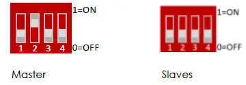
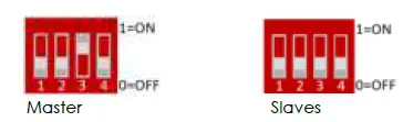
- DIP configuration depending on Inverter type:
- Inverter: TURBO ENERGY HI, GOODWE, VICTRON, SOFARSOLAR, SMA, SOLIS, LUX, IMEON, INFINISOLAR, SUNGROW, RENAC, DELIOS, GROWATT HVM

- Inverter: VOLTRONIC Axpert-VMIII/Axpert King, Growatt SPH/SPA

- Inverter: GROWATT SPH/SPA

- Inverter: GROWATT SPF HVM
- Inverter: TURBO ENERGY HI, GOODWE, VICTRON, SOFARSOLAR, SMA, SOLIS, LUX, IMEON, INFINISOLAR, SUNGROW, RENAC, DELIOS, GROWATT HVM
- If the energy storage system has only one Lithium Series 48V 2.4 kWh, it is the host itself.
Assembly and connection
Components list
| Item | Specification | Quantity | Figure |
| Battery-B4850 | 48V/50Ah 480×360×90mm | 1 |
|
| Power cable- positive | Red /25mm2/L2050m m | 1 |
|
| Power cable- negative | Black /25mm2/L2050m m |
1 | 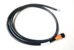
|
| Parallel cable- positive | Red /25mm2/L215mm | 1 | |
| Parallel cable- negative | Black /25mm2/L215mm | 1 | |
| Communicati on parallel cable | Black /L250mm/Double RJ45 plug | 1 | |
| Communicat on cable-to inverter | Black /L2000mm /Double RJ45 plug | 1 |  |
| Ground wire | L500mm,4mm² |
1 |  |
| User Manual | LIS 24 User manual | 1 |  |

Mechanical instalation
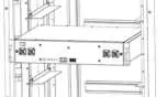
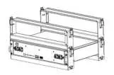
Installation method 1: With rack installation
- Place the Lithium Series 48V 2.4kWh unit on the rack bracket as shown in the figure and push the device into the cabin at the installation position. (The cabinet structure in the figure is for reference only)

- Secure the Lithium Series 48V 2.4 kWh unit to the rack with a nut through the mounting holes top on the hanging ears of the unit.

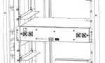
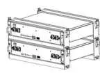
Installation method 2: With simple bracket installation
- Place the Lithium Series 48V 2.4 kWh and brackets as shown in the figure and insert it into the brackets. Use 4 screws to fix the module on the front bracket.

- Install another pair of brackets on the first one, fixed by buckles between them

- Insert the second one Lithium Series 48V 2.4 kWh into the brackets and repeat for more batteries.
Electrical installation
Before connecting the power cables, use multimeter to measure cable continuity, short circuit, confirm positive and negative, and accurately mark the cable labels.
Measuring methods:
- Power cable check: select the buzzer mode of multimeter and detect both ends of the same color cable. If the buzzer calls, it means the cable is in good condition.
- Short circuit judgment: choose multimeter resistor file, probe the same end of positive and negative pole, if the resistor shows infinity, means that the cable is available.
- After visual testing of power line is connection, the positive and negative poles of the battery shall be connected respectively to the positive and negative poles of the opposite terminal.
It is better to add a circuit breaker between the inverter and the battery system. The selection of the circuit breaker requires:
- Voltage: U>60V
- Current: I =
45V
The circuit breaker is installed between the battery module and the inverter, as shown in next figure: 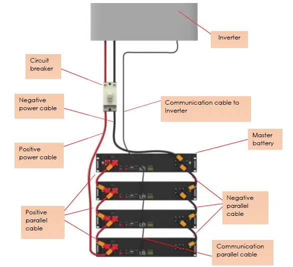 Important:
Connect the specific communication cable supplied by the provider.
Connect the communication cable between batteries.
After the whole system connection, set the master DIP mode according to the inverter model firstly, then start the battery.
The BAT-INV comms cable is from inverter comm port to master CAN IN port, BAT-BAT cable is from master CAN OUT to slave1 CAN IN, slave1 CAN OUT to slave2
CAN IN…
Each pair of power cable, it is limited continuous current is 120A, so if the inverter Max. work current more than 120A, please add power cable according to the proportion.
Warning when doing a battery expansion: It is very important that in the case of connecting batteries in parallel that are not new (for example, we add a new battery to an existing system), we previously perform a voltage balancing (without load) between them to avoid overcurrents that could damage the system. As an alternative to balancing voltages, balancing can be done by equalizing the SOC of the batteries. In addition, when connecting new batteries, we must take into account that the number of batteries at the time of connection must be similar to the number of batteries that are already connected in the system. For example, if we have 30 batteries installed and we want to connect 5 new ones, we must first connect the new batteries with 5 of the 30 that were already in place to balance them, then connect these 10 with another 10 old batteries, and finally connect the remaining 15 old batteries with the group of 20. Batteries should always be connected in groups of similar numbers so that a large group cannot damage a smaller group of batteries at the time of connection.
Battery parameter settings on the inverter
The following parameters must be set into inverter settings:
- Max Charging (Bulk) Voltage: 53.5V
- Absorption Voltage: 53V
- Float Voltage: 52.5V
- Shut Down (cut off) Voltage: 47V
- Shut Down (cut off) SOC: 20%
- Restart Voltage: 49V
- Max Charge Current: 25A*battery QTY
- Max Discharge Current: 25A * battery QTY
- Capacity: 50Ah* battery QTY
Use, maintenance and problem solving
Commissioning and use of the equipment
After completing the electrical installation, follow these steps to start the battery system:
- Refer to the description of the DIP switch of 4.2. to prepare the battery module before starting up, then press the ON/OFF button to the ON position, next press and hold the SW button for 3 seconds.
- After the indicator self-test, the RUN indicator will light and the SOC indicator will be on (100% SOC status in the figure)
 Caution
After pressing the power button, if the battery status indicator on the front panel continues to be red, please refer to the “5.2 Alarm description and processing “. If the failure cannot be eliminated, please contact the dealer timely. - Use a voltmeter to measure whether the voltage of the circuit breaker battery access terminal is higher than 42V, and check whether the voltage polarity is consistent with the inverter input polarity. If the circuit breaker battery input terminal has a voltage output and is greater than 42V, then the battery begun to work normally.
- After confirming that the battery output voltage and polarity are correct, turn on the inverter, close the circuit breaker.
- Check if the indicator of the inverter and battery connection (communication indicator and battery access status indicator) is normal. If it is normal, successfully complete the connection between the battery and the inverter. If the indicator light is abnormal, please refer to the inverter manual for the cause or contact the dealer.
- Battery modules can be connected in parallel up to 40 units.
 Caution
| Equipment Use | Charging |
|
| Discharging |
|
Alarm description and processing
When protection mode is activated or system failure occurred, the alarm signal will be given through the working status indicator on the front panel of the LS 2,4 kWh. The network management can query the specific alarm categories.
If the fault such as single cell overvoltage, charging over-current, under-voltage protection, high-temp protection and other abnormalities which affects the output, please deal with it according to the following table.
| Status | Alarm category | Alarm indication | Processing |
| Charge state | Over-current | RED, Buzzer start | Stop charging and find out the cause of the trouble |
| High temp | RED | Stop charging |
| Status | Alarm category | Alarm indication | Processing |
| Discharge state | Over-current | RED Buzzer start | Stop discharging and find out the cause of the trouble |
| High temp | RED | Stop discharging and find out the cause of the trouble | |
| Total voltage undervoltage | RED Buzzer start | Start charging | |
| Cell voltage undervoltage | RED Buzzer start | Start charging |
Common faults analysis and treatment
| No | Fault phenomenon | Reason analysis | Solution |
| 1 | The indicator does not respond after the power on | Total voltage lower than 35V | Check the total voltage |
| 2 | No DC output | Battery data status is abnormal. Battery gets into over-discharged protection | Read the battery information on the monitor. |
| 3 | The DC power supply time is too short | Battery capacity become smaller | Storage battery replacement or add more modules |
| 4 | The battery cannot be fully charged to 100% | Charging voltage is too low | Adjust charging voltage at 53.5V or 54V |
| 5 | The power cable sparks once power on and ALM light RED | Power connection short-circuit | Turn off the battery, check the cause of the short circuit |
| 6 | Communication fault | The DIP setting of the host is wrong/ the battery type of the inverter is wrong/ Communication cable used incorrectly/ communication cable is incorrectly connected at the battery comm port or the inverter comm port/ The battery firmware version is not supporting the inverter | Check these possible causes one by one |
Appendix
Safety instructions
- Please read the battery instructions before use.
- Keep the battery away from high voltage and out of reach of children.
- In operation, the battery should be kept in the set temperature ranges (between -20ºC and 50ºC) and a humidity less than 85%.
- During handling, be very careful to avoid bumps/falls of the battery.
- Be careful not to touch the contacts at the same time.
- The battery, at the end of its useful life, requires a recovery process, not disassemble it.
- Avoid locating batteries in damp places to avoid danger.
- When not in use for a long time, store the battery intact and let the battery be half charged. Wrap the battery with non-conductive material to avoid direct contact of the metal. Store the battery in a cool, dry place.
- Never expose the battery to fire or water.
Safety warnings
- Do not disassemble the batteries. The inside of the battery has a protective mechanism and a protective circuit to avoid danger. Improper disassembly will damage the protection function permanently, leaving the battery without safety conditions.
- Never short-circuit the poles of the battery. Avoid contact of positive and negative poles with metals.
- Keep the batteries away from fire and extreme temperatures. Monitor the distance to thermal bulbs, stoves, etc.
- Keep the battery away from the water. Always be careful that the battery is not located in damp places where the dew point can be reached.
- Do not use batteries that have physical damage that may be due to falls or bumps.
- Do not weld near the battery.
- Overheating will result in the loss of the protective function of its life cycle, even, it could render the battery useless and in extreme cases self-ignition of the battery occurs.
- Never connect this battery in series and connect it in parallel only with identical batteries up to a maximum number of 6.
- If the battery has liquid leakage, avoid contact with it completely. It can be harmful to the skin, and if you touch the eyes, wash, and go to the hospital immediately for treatment.
Environmental protection
Turbo Energy’s batteries comply with EU ROHS regulations.
Contact details
For any incident with the battery write, indicating your contact details, an email to the address: [email protected] and we will contact you as soon as possible.


