![]()
INSTALLATION MANUAL
SS4037-11
Advanced Lithium-Ion battery
Introduction
This manual is intended to provide assistance to an installer for the installation and commissioning of the range of Solar MD Lithium Ion phosphate (LiFePO4) energy storage solutions.
Product Description
The SS4037-11 battery solution is available in one standard size and can be paralleled to meet most residential applications. The rated voltage is 51.2V nominal (to suit 48V systems).
Larger systems are provided by Solar MD based on specific project requirements.
WARNING: Read the entire document before installing or using the Solar MD battery. Failure to comply with the instructions or warnings in this document could result in electrical shock or serious injury that can result in death or damage to the product that can render the SS4037 Solar MD battery inoperable.
Product Specifications
All SS4037-11 specifications & descriptions contained in this document are verified to be accurate at the time of printing. Solar MD reserves the right to make any product revisions & improvements at any time.
Errors or Inaccuracies
To communicate any inaccuracies, omissions or to provide general feedback regarding this manual, send an email to [email protected]
Copyrights
All information in this document is subject to the copyright of Solar MD (Pty) Ltd. Additional information is available upon request.
Safety Information
This manual contains important instructions and warnings that must be followed when using SS4037-11.
Read all instructions before installing and using the SS4037-11.
⚠ Warnings
⚠ Cautions
- Use SS4037-11 only as instructed.
- For communication and other information please read the BMS manual.
- Do not attempt to disassemble, repair, modify, or tamper with this battery unit.
- Do not insert foreign objects into any part of battery unit.
- Avoid exposure to any moisture.
- Do not expose to extreme temperatures.
- Do not drill any holes into the box.
- Use only an approved Solar MD installer to install this product.
Failure to comply will void the warranty
Specification
| Solar MD 3.7kWh SS4037-11 specification | |||
| Battery type | Lithium Iron Phosphate | Scalability | Yes |
| • Battery module | SS4037-11 | Communication | CANBUS 500kbps/CAN 2.0B |
| Rated battery capacity | 3686 Wh | Can BUS termination | Single 120 Ohm |
| Output power | Max S kW/100A 1.38C | Canbus id range: | 256 – 499 |
| Usable battery energy @ 0.3\C | 3.68 kWh | Protection method | Cell level: uv/ov/oc Position: x/y/x Acceleration: x/y/z Temperature: of/ut |
| Nominal voltage | 51.2V | Protection phy | Mechanical relay NO |
| Number of battery modules | 1 module | Com (CANBUS ) isolation | Yes 1.5kV |
| Weight | 37kg | Transportation protection | Yes |
| Operating voltage | 44.8V-55.6Vdc | Indicator | Led, programmable |
| Communication | CANBUS | Addition 10 | 3 GPO |
| Dimensions of 5544037: h/w/d | 620mm/320mm /200mm | Cell balancing | Passive balancing |
| Net Weight of 554037 | 35 Kg | Counters | Cycle counters and SoH |
| Battery cycle life [+25 ‘C] | > 4000 | AUX power output | 5V 1A max |
| Charging efficiency | 99% | Storage duration | 6 months@+25°C |
| Operating temperature | -5°C -+50°C | Safety standards compliance | IEC 62619/UN 38.3/UL1642 |
| Transport | UN3480 & UN38.3 | Cell Certificate | TUV / CE / RCM / UL1642 |
Mechanical installation
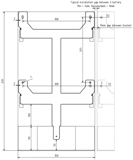
Figure 1: Rear Battery Bracket
Please use the correct mounting screws for the correct wall surface. Screw head should not be bigger than 16mm in diameter. The Battery is only to be installed in the upright position with a maximum tilt angle of 30 degrees.
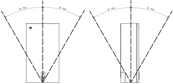
Figure 2: Maximum tilt angle
Installing bottom cover plate
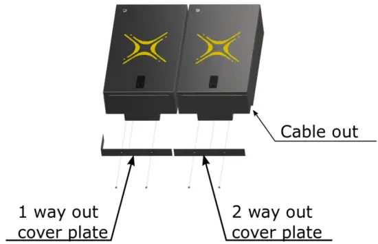
Figure 3: Bottom cover installation for single or dual cable exit points
The Battery comes with two covers for single or dual cable exit points. Use the 1 or 2 way out cover plate and fix it with the two M5x6 bolts provided in the box.
Electrical installation
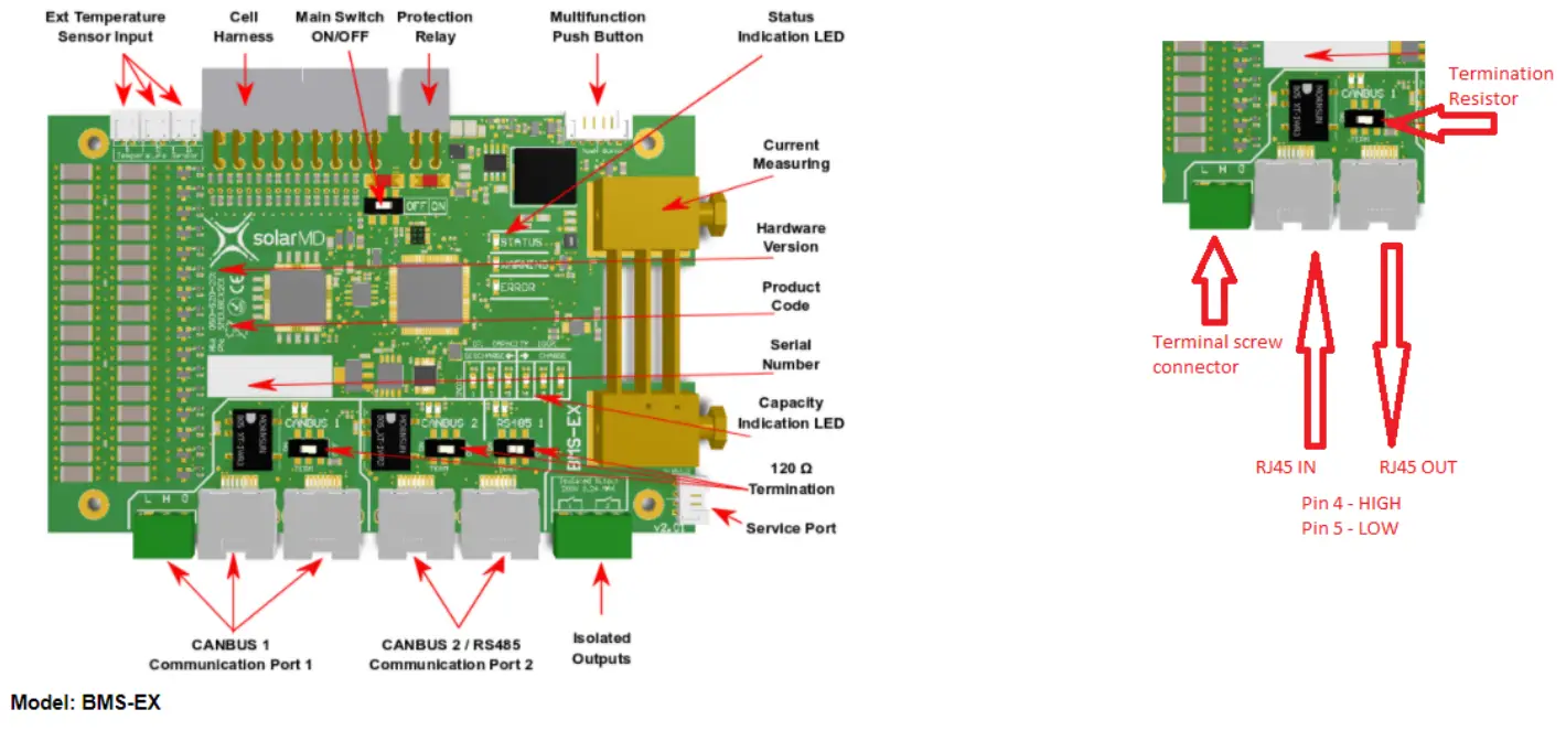
Step 1. Before connecting anything be sure that battery is off and the ON/OFF switch (fig4 pos 3) is in the OFF position.
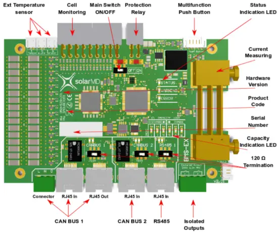
Figure 4: BMS board component location
 Connecting Inverters/chargers/UPS to the battery unit while it is ON can cause big sparks due to capacitors inside the connected device. This could cause serious injuries.
Connecting main battery terminal must be with the correct size cable.
Based on the rated current of the battery and inverter as well as cable length.
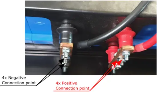
Figure 5 connection terminal
Step 2. Connect the negative cable to the battery negative busbar and positive to battery positive as shown is figure 5 Make sure that all the connections are tight.
All used connection points should be a suitably tightened, ensuring good electrical connection between the lug and busbar. A bad connection could cause serious damage to the battery and inverter, and could void the warranty.
Commissioning
Step 1. Ensure all DC cables are tight according to specifications.
Step 2. If the battery operates in parallel with other Energy sources, make sure that the difference between battery voltage and DC bus is not more than 2.5V. If greater than 2.5V please Charge or Discharge other source accordingly until voltage difference is in safe ranges under 2.5V. Caution! A hot connection with difference in voltage can cause very high equalization current which can burn the fuses of the battery! Caution! Measure the voltage of the battery before connecting the dc Cables.
Step 3. Turn BMS board ON/OFF switch to the ON position (figure 4 pos 3)
Step 4. Connect Multi-purpose button if not connected to the BMS board connector see (figure 4 pos 5)
Step 5. Hold multi-purpose button until light come on.
Note: If commissioning two or more batteries.
Once the system is switched on and load is added, measure current flow on each battery. Ensure that the load is distributed across each battery equally.
Warning! If the battery does not switch the main protection Contact ON in 7 seconds, please check BMS board indication LED for faults. See section BMS Error and Warnings on page 12 of this manual.
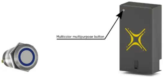
Figure 6: Multicolor/Multipurpose button.
The new Solar MD Multipurpose button has an extended functionality in combination with the BMS-EX.
The Multipurpose Button can be used to directly execute 6 predefined functions and a shutdown instruction. In combination with the 6 Indication LEDs on BMS-EX, the user can choose between each function by holding the button until the LEDs count match the number of the function. By releasing the button while moving through the functions, LEDs will start blinking and wait for the user to press the button again within 3 seconds.
The predefined functions are:
- Reserved
- Change indication LED function between: Show Capacity, Show Current, and Off
- Reserved
- Wake up if Sleep mode is active.
- Activate Override Off state for 60sec
- Activate Override On state for 60sec
If the button is held continuously after function 6, shutdown mode is activated and the battery will send a signal to switch off in 4sec.
Further holding the button causes the BMS to delay complete shutdown for a maximum of 3 minutes. This operation is used when the technician wants to continue read or write parameters after shutdown.
**Access to all features in future development
The Multipurpose button advanced indication functionality, allows the user to choose between 5 different states. Mixed combinations are also allowed when a combination of multiple batteries with BMS-EX are used. The User can change the prefered stage by logging into his mypower24 Energy Portal and go to the Battery Settings.
Illumination off
**For future development
When this state has been selected, the button serves as an on/off switch without illumination (fixed colour).
Color based on capacity
When this state has been selected, the button shows static illumination in a color based on the state of charge.
From RED at 0% SoC (State of Charge) to GREEN at 100% state of charge.
Color based on capacity with current direction based on shading.
**For future development
When this state has been selected, the button shows flashing illumination in a color based on the state of charge and flashing code based on the electrical current direction (charge / discharge). From RED at 0% SoC (State of Charge) to GREEN at 100% state of charge. The flashing code for charge goes through illumination interruption for 1 interval and slow illumination into the color based on the SoC for 5 intervals. The flashing code for discharge represents the opposite from charge – study color for 1 interval and slow loss of color following illumination interruption. Solar MD users refer for both as charging / discharging waves.
Fixed color with current direction based in shading
**For future development
When this state has been selected, the button shows illumination in a color based on the user choice and flashing code based on the electrical current direction (charge/discharge). The flashing code for charge goes through illumination interruption for 1 interval and slow illumination for 5 intervals. The flashing code for discharge represents the opposite from charge – study color for 1 interval and slow loss of color following illumination interruption. Solar MD users refer for both as charging/discharging waves.
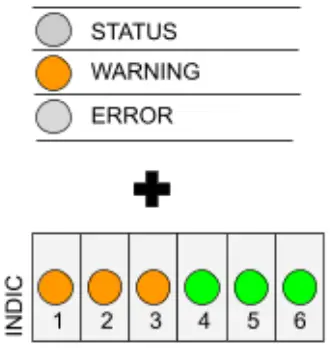
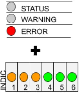
BMS Warnings and Errors
Method of displaying general warnings and errors:
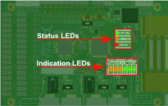
Figure 7 : Display general warnings and errors, Main status LEDs and Indication LEDs.
The Status LEDs determine what the indication LEDs will show.
- If the Status LED is Green the indication LEDs will show:
a) Battery capacity
b) Current flow and direction
c) Off
The functionality of the indication LEDs are configurable, see more on this: multifunction push button. - If the Warning LED is Orange
a) The indication LEDs will show the warning number in binary, which corresponds to that tabulated below in the warning register. - If the Error LED is Red
a) The indication LEDs will show the error number in binary, which corresponds to that tabulated below in the error register.
Warning Register
| Warning Code | Visual Representation | Description |
 | If the Warning LED blinks ORANGE refer to the indication LEDs to find the corresponding warning event in the table below | |
| 30 | 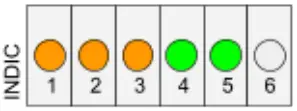 | Pending Awake High |
| 29 | 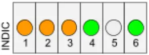 | Pending Awake Low |
| 28 | 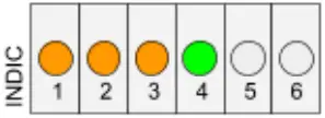 | Positive fuse blown |
| 27 | 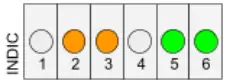 | Negative fuse blown |
| 26 | 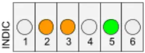 | • Override ON active |
| 25 | 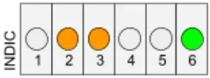 | • Override OFF active |
| 11 | 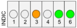 | Discharge current too high |
| 10 | 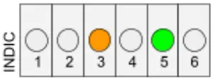 | Charge current too high |
| 9 | 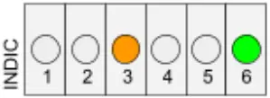 | Cell temperature too low |
| 8 | 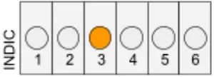 | Cell temperature too high |
| 2 | 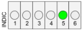 | Battery cell voltage too high |
| 1 | 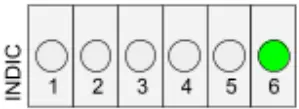 | Battery cell voltage too low |
Error Register
| Error Code | Visual Representation | Description |
 | If the Error LED blinks RED, refer to the indication LEDs to find the corresponding Error event in the table below | |
| 31 | 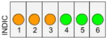 | Max 14921 not responding (Cell monitoring) |
| 30 | | Max 14921 thermal shutdown |
| 29 | | Open cell detected |
| 28 | | Internal EEPROM error |
| 27 | | External EEPROM error |
| 26 | | Balancing error internal FET circuit |
| 25 | | ADC reference not correct |
| 24 | 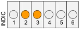 | • Override On out of range |
| 23 | 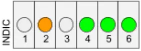 | Internal fault |
| 22 | 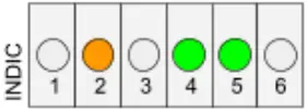 | Cell overvoltage |
| 21 | 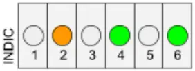 | • Charge Over current |
| 20 | 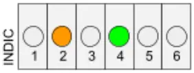 | Pack overvoltage |
| 19 | 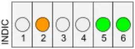 | Pack undervoltage |
| 18 | 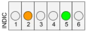 | Pack undervoltage |
| 17 | 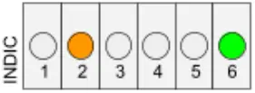 | Over current charge |
| 16 | 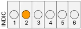 | Over current discharge |
| 15 | 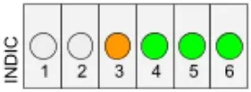 | User shutdown init |
| 14 | 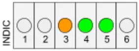 | Remote shutdown init |
| 10 | 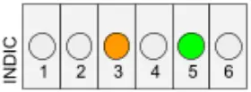 | Relay coil over current |
| 9 | | Relay fuse blown |
| 8 | | Relay coil open |
| 7 | 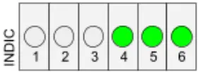 | Gyro Z out of range |
| 6 | 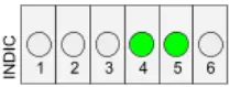 | Gyro Y out of range |
| 5 | 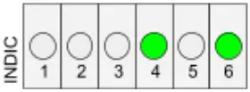 | Gyro X out of range |
| 4 | 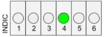 | • Ext NTC 3 fault |
| 3 | 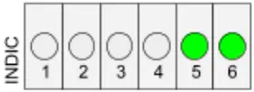 | • Ext NTC 2 fault |
| 2 | | • Ext NTC 1 fault |
| 1 | | Cell temperature too high |
CANBUS connection.
Bms EX used CAN 2.0B @ 500000 kb. Connecting other device operating at different speed rate is not allowed. For connection please use twisted pair wires in a shielded cable to minimize RF emissions.
RJ45 connections can be used for daisy chaining BMS EX together using a straight Ethernet cable.
The output of the Bms EX CAN transceiver is galvanically isolated.
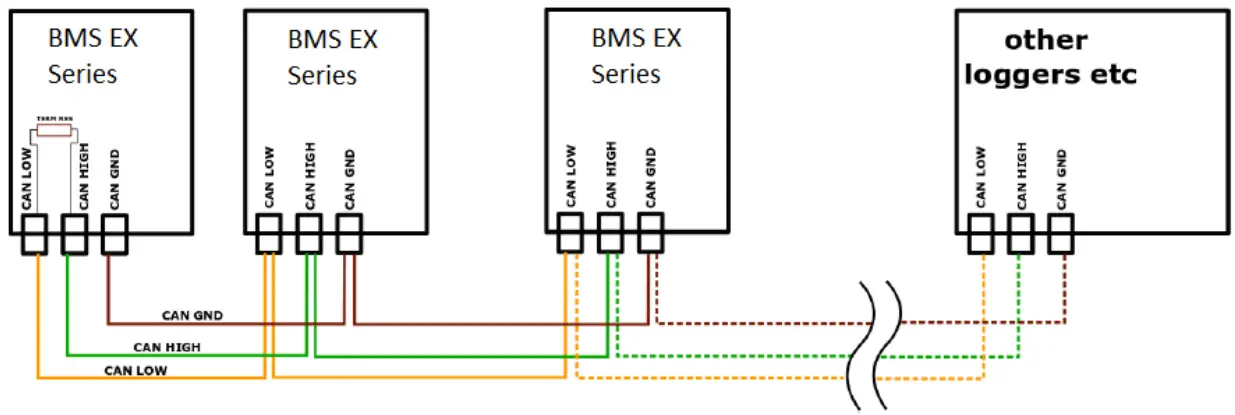
Figure 8: BMS-E connection to the CANBUS.
CANBUS warnings.
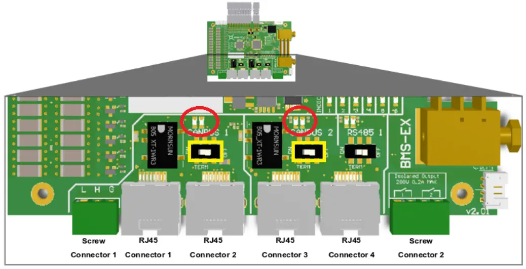
Figure 9 CANBUS Termination resistor and Warning LED location
The Orange LED (WARN) is used to display warning for canbus only. Reading this warning is possible with pulse counting.

![]()
– CANBUS line open or no termination resistor set. [1]
![]()
– CAN BUS line in initialization stage. Canbus init occur when the line was opened and then established. Minimum period for initialization is 30sec. In this period all nodes are scanned in the network and scanned for ID and serial number collisions. [2]
![]()
– Duplicate CAN ID detected with no “auto ID” set. [3]
![]()
– Duplicate Serial number detected. [4]
![]()
– CANBUS Internal fault. [5]
Troubleshooting Warnings/Errors
Code | Cause | Solution |
Warnings ( Figure 6) | ||
| 1-2 | 1. Inverter/rectifier settings may not be correct. 2. Battery cells may be disbalanced | 1. Check the battery settings 2. Contact Solar MD support |
| 3-4 | System design is not correct. | Add additional battery, decrease charging/discharging current from your inverter/rectifier/load |
| 5-6 | Manual override | Manual override has been activated – please check with your installer |
| 29-30 | The BMS is ready to switch on after deep discharge/charge | Connect charger/load to the Battery |
Errors (Figure 7 & 8) | ||
| 5,6.7 | The battery is not installed in upright position | Install the battery in the right position |
| 15,16,17 | The BMS has been shut down manually or remotely | Switch on the BMS |
| 18,19 | The absolute maximum charge/discharge current has been achieved | The BMS will restart automatically, please contact support team or approved installer |
| 21 | The BMS is set for different number cells in series as the actually installed | Contact your installer or Solar MD support team |
| cvt22 | Battery cell voltage way too low. | Fill in the failure report and send to [email protected] The unit needs to return to the factory for testing |
| 23 | Battery cell voltage way too high | The BMS will restart automatically after pending awake condition |
| 24, 25, 26, 27, 28, 30, 31 | BMS Internal failure | Fill in the failure report and send to [email protected] The BMS will be dispatched to you for replacement |
| 29 | Battery factory failure | Fill in the failure report and send to [email protected] The unit needs to return to the factory for testing |
CANBUS Warning (Figure 10) | ||
| 1 | 1. Canbus line open. 2. Single CANBUS resistor not terminated. | 1. Check if the minimum of two nodes are connected on the line with the same transmission speed. 2. Check if single resistor is terminated via the jumper. Located top left of can LEDS(Fig 10). |
Maximum charging/discharging voltages for non supported devices.
– Bulk charge (stop charging) 54.6V
– Float charge (if applicable) 53.8V
– Low battery discharge: 48V
Check that the Equalisation function are disalled, then verify if there is a voltage difference on the inverter display and the battery terminals @0.3C discharge/charge current. If so adjust the values above.
Please check if your inverter charger has been approved by Solar MD and it is CAN compatible.
For the latest Solar MD installation documents go to: www.solarmd.com
To secure the full 10-year product warranty for the end user, be sure to register your battery online – login.mypower24.co.za.
Solar MD (PTY) ltd.
Unit 23, Alternator Park
Montague Gardens 7441
Cape Town, South Africa
E: [email protected]
T: (021) 555 2181.


