![]() Installation Instructions
Installation Instructions
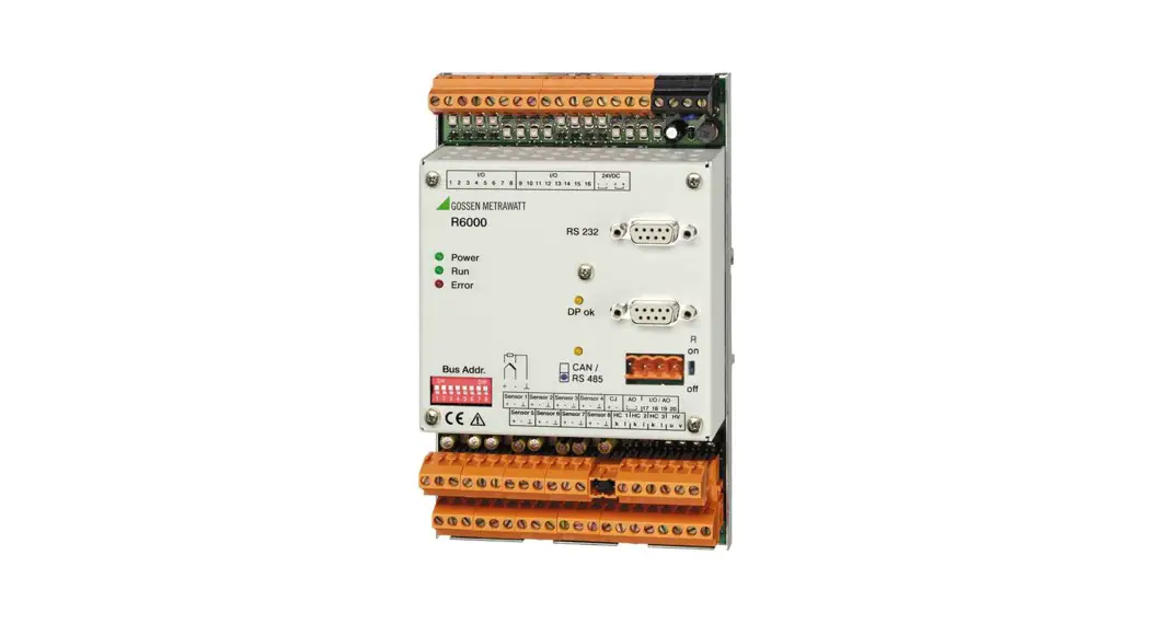
R6000
3-349-163-29
10/9.22
8-Channel Controller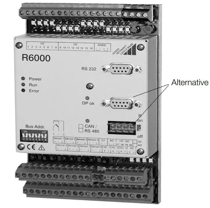
Safety Precautions
The R6000 controller is manufactured and tested in accordance with safety regulations IEC 61010-1 / EN 61010-1 / VDE 0411 part 1.
If used for its intended purpose, safety of the user and of the device is assured.
![]() Attention!
Attention!
Check the specified nominal voltage at the front housing panel before placing the instrument into service.
Make sure the connector cables are not damaged, and that they are voltage-free while wiring the instrument.
If it can be assumed that safe operation is no longer possible, the device must be immediately removed from service (disconnect auxiliary voltage!).
Safe operation can no longer be relied upon if the device demonstrates visible damage.
The device may not be placed back into operation until troubleshooting, repair and subsequent testing have been performed at our factory, or by one of our authorized service centers.
Work on live open instruments may only be carried out by trained personnel who are familiar with the dangers involved.
Capacitors inside the device may be dangerously charged, even if it has been disconnected from all power sources.
Requirements set forth in VDE 0100 must be observed during the performance of all work.
Safety clearances to neighboring electrical circuits with dangerous voltages must be maintained during installation.
1.1 Meanings of symbols on the instrument![]() Warning concerning a point of danger
Warning concerning a point of danger
(Attention: observe documentation!)![]() Indicates CE conformity
Indicates CE conformity![]() This device may not be disposed with the trash. For further details on the WEEE marking, please refer to our website www.gossenmetrawatt.com and enter search key ’WEEE’.
This device may not be disposed with the trash. For further details on the WEEE marking, please refer to our website www.gossenmetrawatt.com and enter search key ’WEEE’.
Identification by Means of Serial Plate
The controller is identified by means of a serial plate. The serial plate is located on the left-hand side of the housing. 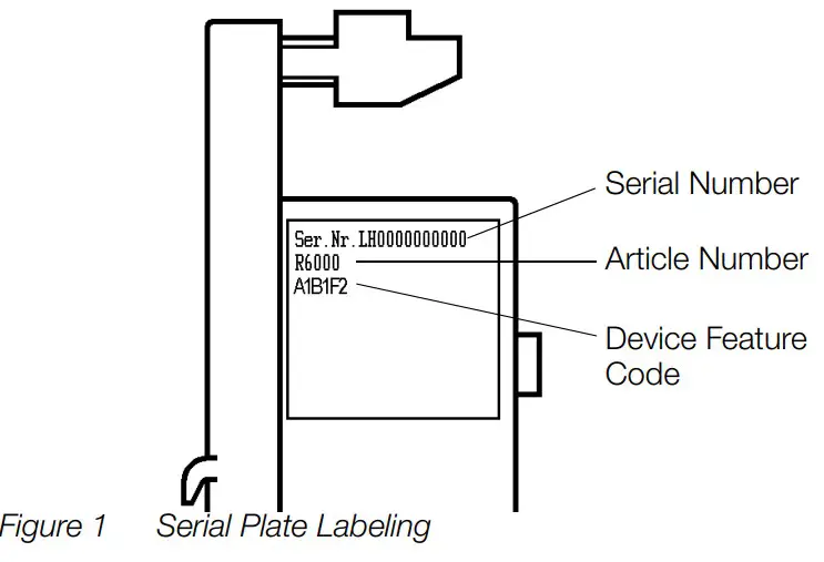 2.1 Identification According to Article Number and Device Feature Code
| Article Number / Feature | Description |
| R6000 | 8-Channel Controller |
| Inputs / Outputs | |
| A0 | 16 binary inputs / outputs |
| A1 | 20 binary inputs / outputs |
| A2 | 16 binary inputs / outputs, 4 continuous outputs |
| Measurement Input | |
| B1 | Thermocouple, Pt100 |
| Connectors | |
| D0 | Screw terminal blocks |
| D1 | Clamp-type terminal blocks |
| Bus Interface | |
| F1 | CAN / CANOpen |
| F2 | Profibus DP |
| F3 | RS 485 / Modbus protocol |
| F4 | RS 485 / EN 60870 protocol |
2.2 Identification of Features at the Housing Front Panel 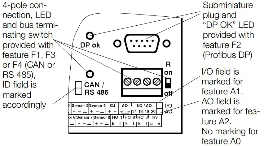 Figure 2 Device Variant According to Included Features
Mounting, Setup and Installation Instructions
The R6000 is a compact 8-channel temperature controller in a top-hat rail mount housing. The controller is mounted by snapping it onto a top-hat rail in accordance with DIN EN 50022.
During installation make sure to keep safe distances to adjoining electrical circuits involving hazardous voltages.![]() Attention!
Attention!
A sensor type must be selected for each channel with the DIP switch at the left-hand side of the housing before mounting.
Unused inputs must be set to thermocouple.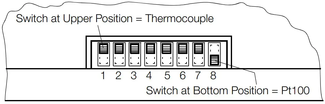 The factory default setting is always thermocouple.
Figure 3 Selecting a Sensor Type
Unobstructed air circulation must always be assured when one or several devices are installed.
The ambient temperature underneath the devices may not exceed 50° C.
Aggressive vapors shorten the service life of the controller.
3.1 Dimensional Drawing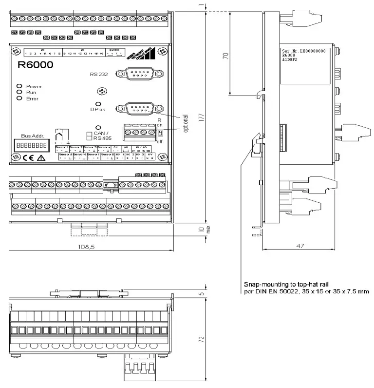 All dimensions in millimeters
Figure 4 Dimensional Drawing for Top-Hat Rail Mounting
Electrical Connection
![]() Attention!
Attention!
Observe terminal assignments at the housing front panel!
The instrument is not equipped with an integrated circuit breaker.
Therefore, during installation, care should be taken to ensure that
– the building where the instrument is installed includes a circuit breaker,
– the circuit breaker is positioned in close proximity to the instrument and is easily accessible to the operator
– it is clearly marked as a circuit breaking device for the instrument.
Tighten screws with a manual screwdriver only!
Maximum tightening torque for all screw connections is 0.6 Nm.
Connectors: Terminal blocks for wires with cross-sections of up to 2.5 square mm, or two-core wire-end ferrules for cross-sections of up to 2 x 1.0 square mm
EN 55022 requires the following warning as regards electromagnetic compatibility:
Warning
This is a class A device. It may cause radio interference in residential environments.
If this is the case, the operator may be required to implement appropriate corrective measures.
Reliable wiring is accomplished with the help of screw and clamp-type terminals which are separated according to function. Only terminal blocks of like polarity or identical color may be plugged onto the appropriate bases.
Mismatching of the terminal blocks may result in damage to the R6000 controller or interconnected components.
4.1 Terminal Assignments 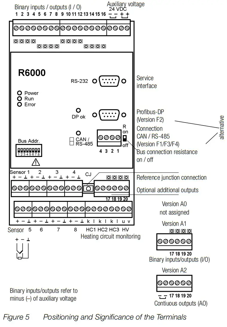 4.2 Auxiliary Voltage
Auxiliary voltage is 24 V DC.
The two connector terminals for the negative poles are connected with one another inside the device, as is also the case for the two positive poles.
In this way, supply power can be looped through to several R6000 controllers. The terminals have a maximum current carrying capacity of 10 A (also in the event of malfunction) which may not be exceeded!
The terminal block for auxiliary voltage is black.
A completely separate safety power supply system is to be used for operation of the instrument.
4.3 Binary Inputs / Outputs (I/O)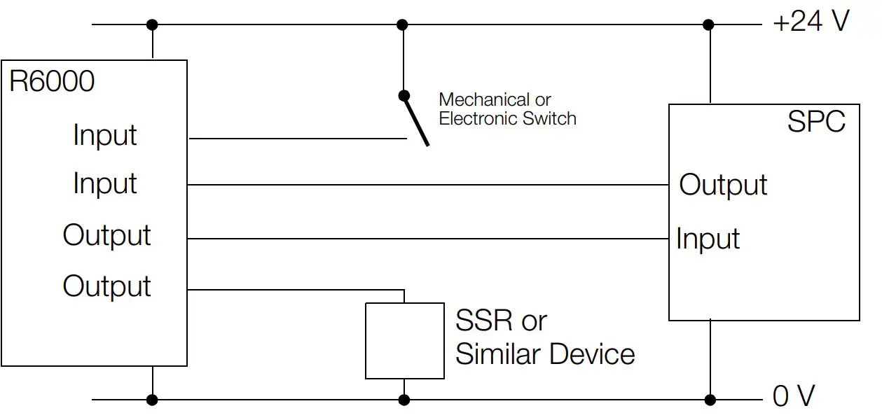
Figure 6 Schematic Diagram, Binary Inputs / Outputs
Binary I/Os which are configured as outputs connect the auxiliary voltage positive pole by means of a semiconductor switch. The load (SSR, controller input etc.) is connected to the auxiliary voltage negative pole. Three SSRs can be connected in series for controlling 3-phase heaters.
Maximum load for each individual output is 500 mA, with a limit of 3 A per controller. All outputs are safeguarded by means of integrated, self-restoring overload protection.![]() Attention!
Attention!
After overload protection has been triggered, not only does the overload have to be eliminated, all other outputs must be de-energized as well in order to allow for self-restoration of the circuit breaker. Self-restoration may take several minutes.
If the I/Os are used as inputs, control is accomplished either by means of an active positive signal at the auxiliary voltage negative pole, or with a floating contact which switches the auxiliary voltage positive pole to the input.
The assignment of I/Os to channels and functions can be freely configured via the interface.![]() Attention!
Attention!
Before I/Os used as inputs are configured as such, an active output signal can be read out depending upon configuration.
The output of the connected device may thus be damaged as a result.
4.4 Thermocouple and Pt100 Measurement Inputs (sensors 1 through 8)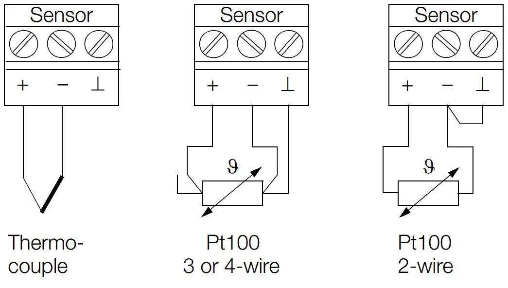 Figure 7 Sensor Terminal Assignments
Thermocouples are connected to the positive and negative terminals.
No connections may be made to the ⊥ terminal.
If impermissible measured values should occur when using insulated thermocouples, all negative legs at the insulated thermocouples should be connected to each other. If necessary, they can be connected to the switch cabinet ground terminal.
3-wire connection is used for Pt100 sensors.
In the event of 2-wire connection, the negative terminal must be connected to the ⊥ terminal at the controller.
The ⊥ terminals are connected with each other internally.
If Pt100 sensors with 4-wire connection are used, the fourth wire may not be connected at all.
The reference junction (CJ) remains attached also for PT100 sensors.
4.5 Remote Cold Junction (CJ)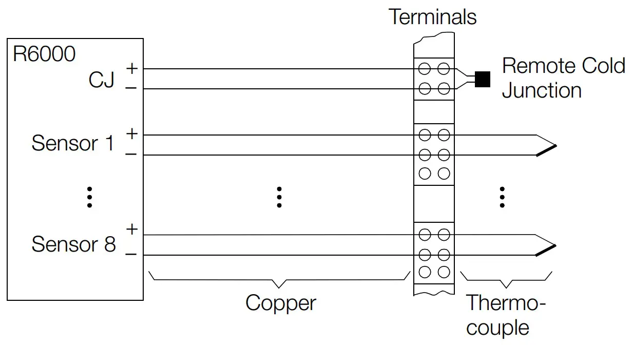
Figure 8 Schematic Diagram, Remote Cold Junction
If the thermocouple equalizing leads are not connected to the controller, the Z306A accessory (remote cold junction) is required. The remote cold junction includes a temperature sensor and a 2-pole terminal block.
The plug-on reference junction (CJ) at the R6000 is removed and is replaced with the 2-pole terminal block. The temperature sensor is attached at the transition from the thermocouple or the equalizing lead to the copper conductor, and is connected to the 2-pole terminal block at the R6000.
The original reference junction which has now been removed from the R6000 is not used.
4.6 Additional Binary Inputs / Outputs (I/O)
Device variants including feature A1 have four additional I/Os.
All of the specifications included in chapter 4.3 on page 9 apply to these I/Os as well.
No connections may be made at the AO negative terminals at the same terminal block.
4.7 Heating Current Monitoring (HC 1 … 3, HV)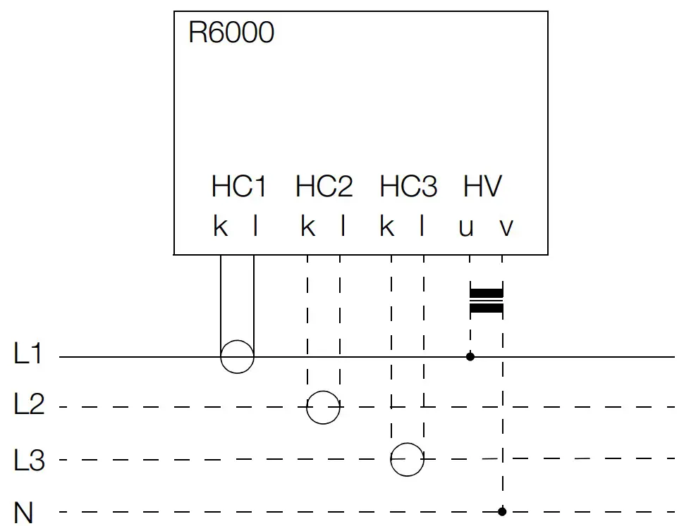 Figure 9 Schematic Diagram, Current Transformer Connection
Commercially available current transformers with max. 1 A secondary current are connected to terminals HC k and l. Compliance voltage is max. 2 V.
Three inputs are provided for monitoring 3-phase current.
Several control loops are monitored via summation current principle.![]() Attention!
Attention!
If the terminal block is removed during operation, excessive voltage occurs at the secondary side of the current transformer.
In order to enable more accurate current monitoring, current fluctuations which result from line voltage fluctuations can be compensated. A voltage transformer with a secondary open-circuit voltage of 12 to 40 V is connected to terminals HV u and v to this end. A representative phase voltage from the heater power supply is used at the primary side. All interconnected transformers must assure safe electrical separation, and may not be connected to each other at the secondary side.
4.8 Data Interfaces
| Type | Service Interface | Fieldbus Interface | ||
| Feature | F2 | F1 | F3/F4 | |
| Interface | RS 232 | Profibus DP | CAN /CANOpen | RS 485 |
| Maximum number of devices | 1 | 32 | 100 | 32 |
| Range of addresses | – | 0 … 126 | 0 … 127 | 0 … 254 |
| Transmission speed | 9.6 or 19.2 kBaud | 9.6 kBaud … 12 MBaud | 10 kBaud … 1 MBaud | 9.6 or 19.2 kBaud |
| Protocol per | EN 60870 | DIN 19245 part 3 | IEC 1131 CANOpen | Modbus / EN 60870/ HB-Therm/ DIN 19244 |
| Connection | 9-pin sub- miniature plug | 9-pin sub- miniature plug | 4-pole screw terminal | |
4.8.1 RS 232 Service Interface
9-pin sub-miniature plug connector at the controller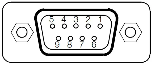 Figure 10 Diagram of Sub-miniature Plug for RS 232 Interface
| Connector Pin Assignments for Sub-miniature Plug Connector for RS 232 Service Interface | Establish connection to | Connector Pin Assignments at the PC COM1 or COM2 | |||
| Pin Number | Designation | Description | Pin Number | Designation | |
| 2 | TxD | Data output | 2 | RxD | |
| 3 | RxD | Data input | 3 | TxD | |
| 5 | GND | Signal ground | 5 | GND | |
| 1, 4, 6 … 9 | Not assigned | ||||
| Socket housing | Shield, con- nected to con- troller housing | ||||
A non-crossed serial extension cable (modem cable) is required for connection to a laptop or a notebook. This can be ordered as an accessory (article no. GTZ 3241000R0001).
With the CAN bus and Profibus variants (features F1 and F2), the service interface can be used independent of bus operation.![]() Attention!
Attention!
With RS 485 variants (features F3, F4), communication is only possible via the service interface after the 4-pole bus plug has been removed, or when the bus is not in use.
4.8.2 Bus Interfaces
The following points must be observed when wiring the bus interfaces:
– Corresponding terminals must all be connected in parallel.
– Wiring must be executed from device to device, devices may not be star-connected.
– The two bus ends should be terminated with characteristic wave impedance.
This is accomplished by setting the “R” switch at the R6000 to “on”.
CAN (variant with feature F1)
4-pole terminal block
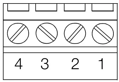 Figure 11 Diagram of Terminal Block for CAN Interface
| Terminal Assignments for CAN Interface Terminal Block | ||
| Terminal Number | Designation | Description |
| 1 | CAN-GND | Ground |
| 2 | CAN-L | Low dominant bus signal |
| 3 | CAN-SHLD | Optional shield, connected to controller housing |
| 4 | CAN-H | High dominant bus signal |
Profibus DP (variant with feature F2)
9-pin sub-miniature plug connector at the controller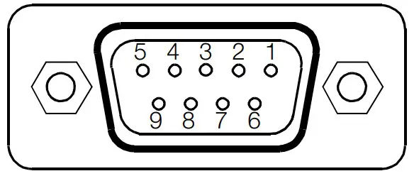 Figure 12 Diagram of Sub-miniature Plug for Profibus DP Interface
| Pin Assignments for Sub-miniature Plug Connector for Profibus DP Interface | ||
| Pin Number | Designation | Assignment / Description |
| 1 | SHIELD | Shield, connected to controller housing |
| 3 | RxD / TxD-P | Bus signal (positive open-circuit level to RxD / TxD-N) |
| 5 | DGND | Signal ground |
| 6 | VP | +5 V supply power for terminating resistor |
| 8 | RxD / TxD-N | Bus signal (negative open-circuit level to RxD / TxD-P) |
| 2, 4, 7, 9 | No connection | |
| Socket housing | Shield, connected to controller housing | |
A commercially available Profibus plug can be used for connection (not included).
RS 485 (variant with feature F3 / F4)
4-pole terminal block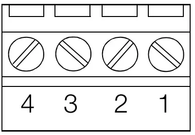 Figure 13 Diagram of Terminal Block for RS 485 Interface
| Terminal Assignments for RS 485 Terminal Block | ||
| Terminal No. | Designation | Description |
| 1 | C = DGND | Ground |
| 2 | A = RxD / TxD-P | Bus signal (positive open-circuit level to RxD / TxD-N) |
| 3 | SHIELD | Optional shield, connected to controller housing |
| 4 | B = RxD / TxD-N | Bus signal (negative open-circuit level to RxD / TxD-P) |
Note![]() Designations A and B are not defined uniformly in various standards or for various devices. If the bus does not function, A and B may be reversed.
Designations A and B are not defined uniformly in various standards or for various devices. If the bus does not function, A and B may be reversed.
LED Functions
LEDs provide information regarding the status of the device, as well as the switching outputs and switching inputs of the controller and the fieldbus.
Status Displays
| Power on | green | LEDs on sheet metal housing |
| Run | green | |
| Active bus communication | yellow | |
| Error | red | |
| Binary input / output is active | yellow | SMD LEDs at terminal blocks |
Initial Start-Up
6.1 Device Configuration
- Selecting the sensor type: see “Mounting, Setup and Installation Instructions” on page 5.
- Selecting the bus address: The bus address is selected with the DIP switch at the front panel.
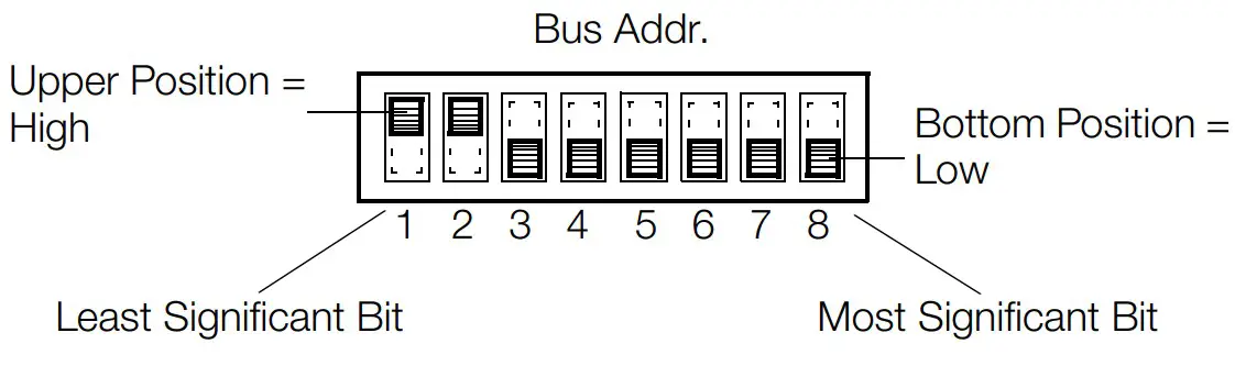 Figure 14 Example: Bus Address = 3
• All other settings are executed via the bus interface or the service interface.
6.2 Device Performance after Connecting Auxiliary Voltage
- As soon as auxiliary voltage is connected, the green “Power” LED lights up.
- Shortly thereafter, the green “Run” LED lights up, and the red “Error” LED blinks once briefly.
- The binary output LEDs then light up in accordance with control loop settings. The binary output LEDs may light up even if auxiliary voltage has not been connected, if the inputs are driven actively.
- The yellow LED for the respective bus terminal indicates active bus communication.
6.3 Possible Errors
Error | Possible Cause |
| Power LED does not light up. | No auxiliary voltage or reversed polarity |
| Run LED does not light up or blinks. | Defective processor or data error |
| Error LED lights up. | Defective hardware |
| Binary output LEDs do not light up. | Short-circuit at output or overload protection has been triggered |
| Binary I/O LEDs continuously illuminated | No connection between negative pole at the actuators and auxiliary voltage |
| Profibus LED does not light up. | No data exchange |
| RS 485 / CAN LED does not light up. | No transmission from R6000e.g. due to incorrect address, bus terminator switch set incorrectly |
Parameters Configuration and Operation
Information regarding parameters configuration and operation of the R6000 is included in the comprehensive operating instructions.
These are available from the internet at www.gossenmetrawatt.de.
Read the operating instructions completely and carefully before using the device, and follow all instructions included therein.
The operating instructions should be made available to all users.
Maintenance and Service
The R6000 controller does not require maintenance at regular intervals.
If the controller should nevertheless require replacement, it can be removed from the rail by pulling on the tab at the bottom of the device.
This disengages the top-hat rail mount and the controller can be removed by lifting it up and forward.
Before replacement, the DIP switches at the replacement device must be configured to match those at the original device (bus address and selection of Pt100 or thermocouple).
The replacement device is attached to the top-hat rail with the mounting hooks at the rear, and is snapped into place by gently pushing down and back.
Screw or clamp-type terminal blocks can plugged from one device to the next for quick device replacement if service is required.
Characteristic Values
| Inputs / Outputs | |
| Sampling rates | 100 ms for each controlled variable |
| Thermocouple Measurement Input | |
| Thermocouples | per IEC 60584 / EN 60584 / DIN 43710 |
| Measuring range | 0 … 50 mV |
| Accuracy / Error | ± 0,3 mV |
| Resolution | 0.1 K |
| Continous overload AC | sinusoidal 50 / 60 Hz / 50 V AC |
| DC | 1 V DC |
| Input impedance | > 50 kW |
| Error meassages | for sensor breakage or polarity reversal |
| Reference Junction Measurement Input | |
| Nominal input range | 0 … 70 °C |
| Accuracy | ± 2 K |
| Reference junction | KTY 10 |
| P1 100 Resistance Thermometer Measurement Input 2 or 3-wire Connection | |
| Pt100 | per IEC 60751 / DIN EN 60751 |
| Measuring range | 18 … 320 W |
| Nominal input range | –200 … 600 °C |
| Sensor current Accuracy / Error | < 0.5 % of measuring range span |
| Resolution | 0.1 K |
| Continuous overload AC | sinusoidal 50 / 60 Hz / 50 V AC |
| DC | 1 V DC |
| Input impedance | 13 kW |
| Cable resistance (both directions) | 2-wire connection: 0 … 30 W adjustable 3-wire connection: 0 … 30 W compensated |
| Error message | for sensor breakage or short circuit |
| Measuring Input 20 mA Heating Current Monitoring Input | |
| Measuring range | 1 A AC (direct connection of a commercially available measuring transducer) |
| Resolution | < 0.1 % of upper range value |
| Accuracy | < 5 % of upper range value |
| Heating Voltage Input | |
| Measuring range | 10 … 50 V AC (direct connection of a commercially available measuring transducer) |
| Resolution | < 0.1 % of upper range value |
| Accuracy | < 5 % of upper range value |
| Binary Inputs / Outputs | |
| Output function | active switching outputs supplied directly from auxiliary voltage |
| Function | controlled variable output / alarm output |
| Read-out cycle | adjustable within a range of 0.1 … 300 s |
| Nominal range of use | H signal: U ³ auxiliary voltage –0.5 V I £ 500 mA total current £ 3 A per device L signal: < 0.1 mA e.g. for driving up to 3 commercially available semiconductor relays (SSR) in series |
| Input function | Read back output status, external control of PLC or similar |
| Nominal range of use | H signal: > 14 V 8 … 16 mA at 24 V L signal: < 7 V / < 0.2 mA |
| Overload limit H, L signal | continuous short-circuit, interruption |
| Continuous Outputs | |
| Output function | actuator output for proportional actuators |
| Output quantity | 0 …10 V at > 1 kW load, 0 … 20 mA at < 300 W load |
| Resolution | 0.1 % of upper range value |
| Accuracy | 2 % of upper range value |
Status Displays
![]()
Auxiliary Voltage
A completely separate safety power supply unit is to be used for operating the controller.
| Nominal value | 24 V DC |
| Nominal range of use | 18 V … 30 V DC |
| Power consumption | max. 10 VA, typically 6 W (without load) |
Data Interfaces
Service Interface
RS 232
| Max. number of devices | 1 |
| Range of addresses | – |
| Transmission speed | 9.6 / 19.2 kBaud |
| Protocol per | EN 60870 |
| Connection | 9-pin sub-miniature plug |
| Field Bus Interfaces Profibus-DP | |
| Max. number of devices | 32 |
| Range of addresses | 0 … 126 |
| Transmission speed | 9.6 kBaud … 12 MBaud |
| Protocol per | EN 50170 |
| Connection | 9-pin sub-miniature plug |
| CAN / CANOpen | |
| Max. number of devices | 100 |
| Range of addresses | 0 … 127 |
| Transmission speed | 10 kBaud … 1 MBaud |
| Protocol per | IEC 1131 CANOpen |
| Connection | 4-pole screw terminal |
| RS 485 | |
| Max. number of devices | 32 |
| Range of addresses | 0 … 254 |
| Transmission speed | 9.6 / 19.2 kBaud |
| Protocol per | Modbus / EN 60870 |
| Connection | 4-pole screw terminal |
Bus Address Selection
The bus address is selected in binary mode with the DIP switch at the front panel.
Service Interface
A laptop or notebook can be connected to the RS 232 interface for service purposes.
Electrical Safety
Attention: The device is not equipped with an integrated circuit breaker
| Design | IEC 61010-1 / EN 61010-1 / VDE 0411, part 1 |
| Safety class | II |
| Measurement category | CAT II |
| Contamination degree | 2 |
| Protection | IEC 60529 / EN 60529 / VDE 0470, part 1 |
| Housing | IP 20 |
| PCB | IP 10 |
| Terminals | IP 20 |
Electromagnetic Compatibility
| Interference emission | IEC 61326-1 / EN 61326-1 |
| Interference immunity | IEC 61326 / A1 / EN 61326 / A1 criterion A, B |
Ambient Conditions
| Annual mean relative humidity, | |
| no condensation | 75% |
| Ambient temperature | |
| – Nominal range of use | 0 °C … + 50 °C |
| – Operating range | 0 °C … + 50 °C |
| – Storage range | – 25 °C … + 70 °C |
Mechanical Design
| Housing | Sheet metal / plastic per UL-V0 |
| Dimensions incl. terminal blocks | |
| (H x W x D) | max. 182 x 109 x 78 mm |
| Weight | approx. 0.6 kg incl. terminal blocks |
| Connectors | terminal blocks for wire cross sections to 2.5 mm 2 or double wire-end ferrules for 2 x 1.0 mm 2 integrated, |
| Mounting | for top-hat rails per DIN EN 50022 35 x 7.5 mm or 35 x 15 mm |
Repair and Replacement Parts Service, and Rental Instrument Service
When you need service, please contact:
GMC-I Service GmbH
Service Center
Beuthener Straße 41
90471 Nürnberg • Germany
Phone +49 911 817718-0
Fax +49 911 817718-253
E-Mail [email protected]
www.gmci-service.com
This address is only valid in Germany.
Please contact our representatives or subsidiaries for service in other countries.
Product Support Industrial Division
When you need support, please contact:
Gossen Metrawatt GmbH
Product Support Hotline – Industrial Division
Phone +49 911 8602-500
Fax +49 911 8602-340
E-Mail [email protected]
© Gossen Metrawatt GmbH
Edited in Germany • Subject to change, errors excepted • PDF version availableon the Internet
All trademarks, registered trademarks, logos, product names, and company names are the property of their respective owners.
Gossen Metrawatt GmbH
Südwestpark 15
90449 Nürnberg • Germany
Phone +49 911 8602-0
Fax +49 911 8602-669
E-Mail [email protected]
www.gossenmetrawatt.com


