![]() VT8000 Room Controllers
VT8000 Room Controllers
VT8350 Installation Guide
Low Voltage (24VAC) Fan Coil Unit (FCU) and Zone Control
Firmware Revision 2.4
SAFETY INFORMATION
IMPORTANT INFORMATION
Read these instructions carefully and look at the equipment to become familiar with the device before trying to install, operate, service or maintain it. The following special messages may appear throughout this bulletin or on the equipment to warn of potential hazards or to call attention to information that clarifies or simplifies a procedure. The addition of either symbol to a “Danger” or “Warning” safety label indicates that an electrical hazard exists which will result in personal injury if the instructions are not followed.
 This is the safety alert symbol. It is used to alert you to potential personal injury hazards. Obey all safety messages that follow this symbol to avoid possible injury or death.
DANGER
DANGER indicates a hazardous situation that, if not avoided, will result in death or serious injury.
WARNING
WARNING indicates a hazardous situation that, if not avoided, could result in death or serious injury.
CAUTION
CAUTION indicates a hazardous situation that, if not avoided, could result in minor or moderate injury.
NOTICE
NOTICE is used to address practices not related to physical injury. The safety alert symbol shall not be used with this signal word.
PLEASE NOTE
Electrical equipment should be installed, operated, serviced, and maintained only by qualified personnel. No responsibility is assumed by Viconics Technologies for any consequences arising out of the use of this material.
A qualified person is one who has skills and knowledge related to the construction, installation, and operation of electrical equipment and has received safety training to recognize and avoid the hazards involved.
BEFORE YOU BEGIN
LOSS OF CONTROL
WARNING
LOSS OF CONTROL
- The designer of any control scheme must consider the potential failure modes of control paths and, for certain critical control functions, provide a means to achieve a safe state during and after a path failure. Examples of critical control functions are emergency stop and over travel stop.
- Separate or redundant control paths must be provided for critical control functions.
- System control paths may include communication links. Consideration must be given to the implications of anticipated transmission delays or failures of the link¹.
- Each implementation of equipment utilizing communication links must be individually and thoroughly tested for proper operation before being placed into service.
Failure to follow these instructions can result in death, serious injury, or equipment damage.
ELECTROSTATIC DISCHARGE
NOTICE
STATIC SENSITIVE COMPONENTS
Circuit boards and option cards can be damaged by static electricity. Observe the electrostatic precautions below when handling controller circuit boards or testing components.
Failure to follow these instructions can result in equipment damage.
Observe the following precautions for handling static-sensitive components:
- Keep static-producing material such as plastic, upholstery, and carpeting out of the immediate work area.
- Store static-sensitive components in protective packaging when they are not installed in the drive.
- When handling a static-sensitive component, wear a conductive wrist strap connected to the component or drive through a minimum of 1 megohm resistance.
- Avoid touching exposed conductors and components leads with skin or clothing.
INSTALLATION
NOTICE
- The system must be installed correctly by a qualified technician.
- If replacing an existing Room Controller, label wires before removal of the Controller.
- Electronic controls are static sensitive devices. Discharge yourself correctly before manipulating and installing Room Controller.
- A short circuit or wrong wiring may permanently damage the Room Controller or equipment.
- All Room Controllers are designed for use as operating controls only and are not safety devices. Tampering with the devices or unintended application of the devices will result in a void of warranty.
- This device must be installed to provide a separation distance of at least 8in (20cm) from all persons and must not be located or operating in conjunction with any other antenna or transmitter.
- Refer to the Room Controller User Interface Guide for information on how to configure the Room Controller.
Failure to follow these instructions can result in equipment damage.
- For additional information about anticipated transmission delays or failures of the link, refer to NEMA ICS 1.1 (latest edition), Safety Guidelines for
the Application, Installation, and Maintenance of Solid-State Control or its equivalent
LOCATION
NOTICE
- Do not install on an exterior wall.
- Do not install behind a door.
- Do not install in areas with a direct heat source.
- Do not install near any air discharge grill.
- Do not install in areas exposed to direct sunlight.
- Ensure the Room Controller has sufficient natural air circulation.
- Ensure the wall surface is flat and clean.
- Ensure external thermal sensor wirings are away from noisy electrical sources.
- Install 1.3 to 1.5 meters (52 to 60 inches) above the floor.
- Perform preventive maintenance on the damper and Variable Air Volume (VAV) box, according to the supplier documentation.
Failure to follow these instructions can result in equipment damage.
CLEANING THE ROOM CONTROLLER
NOTICE
- Use a soft, pre-moistened lint-free cloth for cleaning.
- Avoid getting moisture in openings.
- Do not spray anything directly on the Room Controller or use compressed air.
- Do not use caustic/corrosive products, ammonia, solvents or any cleaning product containing alcohol or grit.
- Never use tools directly on the touchscreen.
- Never use paint on the Room Controller.
- Do not drop or crush the Room Controller, or allow it to come into contact with liquids.
- Do not use a damaged device (such as one with a cracked screen).
Failure to comply with these recommendations will result in damage to the unit and void the manufacturer’s warranty.
INSTALLATION
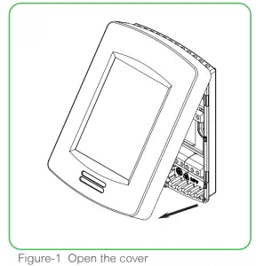
- Remove the security screw (if applicable) from the bottom of the Room Controller cover.
- Open the unit by pulling on the bottom side of the Room Controller (Figure 1).
- Read the FCC ID and IC label installed inside the cover before installing any wireless product.
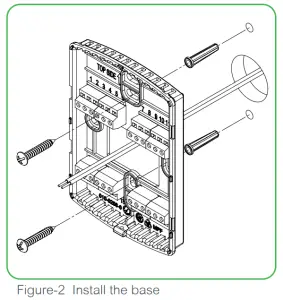
- Ensure the correct side of the base faces up.
- Pull the cables 6in (15cm) out from the wall.
- Align the base and mark the location of the two mounting holes on the wall.
- Install the anchors in the wall (Figure 2).
- Insert the cable in the central hole of the base.
- Insert the screws in the mounting holes on each side of the base.
- Strip each wire 1/4in (0.6cm) from the end.
- Insert each wire and screw according to the wiring chart (see following pages).
- Gently push excess wiring back into the hole.
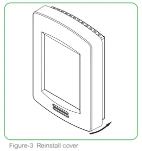
- Gently align the cover with the top of the base and snap it into the place from the bottom (Figure 3).
- Install the security screw (if applicable).
 |  |
 | |
TERMINAL IDENTIFICATION AND FUNCTION
TERMINAL IDENTIFICATION FOR 3-SPEED FAN SYSTEM
| Fan Type – 3-Speed | |||
| Control Type | On/Off | Floating | Analog |
| 1-1301 | Not used | Not used | Not used |
| 2-1302 | Fan-L | Fan-L | Fan-L |
| 3- B03 | Fan-M | Fan-M | Fan-M |
| 4-1304 | Fan-H | Fan-H | Fan-H |
| 5- RC 124 V- Hot | 24 V– Hot | 24 V– Hot | 24 V— Hot |
| 6- C 124 V- Com | 24 V– Com | 24 V– Corn | 24 V— Corn |
| 7- RH | Aux Heat | Aux Heat | Aux Heat |
| 8- B08 | Aux Heat | Aux Heat | Aux Heat |
| 9- U09 | Normally Close Cool Valve | Close Cool Valve | Not used |
| 10- U010 | Normally Close Heat Valve | Close Heat Valve | Not used |
| 11- U011 | Normally Open Cool Valve | Open Cool Valve | Analog Heat Valve |
| 12- U012 | Normally Open Heat Valve | Open Heat Valve | Analog Cool Valve |
| 13- RS485 + | RS485 + | ||
| 14- RS485 – | RS485 – | ||
| 15- RS485 Ref | RS485 Ref | ||
| 16- U116 | U116 Function | ||
| 17- U117 | U117 Function | ||
| 18- Scorn | Common | ||
| 19- U119 | U119 Function | ||
| 20- U120 | Remote Room Sensor | ||
| 21- Scorn | Common | ||
| 22- U122 | Remote Supply Sensor | ||
| 23- U123 | Not used | ||
| 24- U124 | Not used | ||
Fan Type – ECM | |||
| Control Type | On/Off | Floating | Analog |
| 1-B01 | Normally Close Heat Valve | Close Heat Val | Not used |
| 2-B02 | Not used | Not used | Not used |
| 3-B03 | Not used | Not used | Not used |
| 4-B04 | ECM Fan Start | ECM Fan Start | ECM Fan Start |
| 5-RC / 24 V- Hot | 24 V— Hot | 24 V— Hot | 24 V— Hot |
| 6-C/ 24V- Com | 24 V— Com | 24 V— Com | 24 V— Com |
| 7- RH | Aux Heat | Aux Heat | Aux Heat |
| 8- B08 | Aux Heat | Aux Heat | Aux Heat |
| 9- UO9 | Normally Close Cool Valve | Close Cool Valve | Not used |
| 10- U010 | Analog ECM Fan | Analog ECM Fan | Analog ECM Fan |
| 11- U011 | Normally Open Cool Valve | Open Cool Valve | Analog Heat valve |
| 12- U012 | Normally Open Heat Valve | Open Heat Valve | Analog Cool Valve |
| 13- RS485 + | RS485 + | ||
| 14- RS485 – | RS485 – | ||
| 15- RS485 Ref | RS485 Ref | ||
| 16- U116 | U116 Function | ||
| 17- U117 | U117 Function | ||
| 18-Scorn | Common | ||
| 19-U119 | U119 Function | ||
| 20-U120 | Remote Room Sensor | ||
| 21-Scorn | Common | ||
| 22-U122 | Remote Supply Sensor | ||
| 23-U123 | Not used | ||
| 24-U124 | Not used | ||
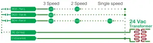
WIRING – SINGLE OR MULTISPEED MOTOR
Power & Fan
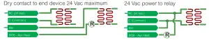
BO8 Auxiliary output wiring
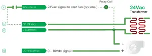
Wiring ECM Motor
Power and Fan
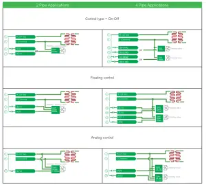
MAIN OUTPUTS WIRING
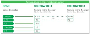
REMOTE SENSOR ACCESSORIES
| Model no. | Description |
| S3010W1031 | Wall-mounted temperature sensor |
| S3020W1031 | Wall-mounted temperature sensor with override button and occupancy status LED |
The VT8350 Room Controller is compatible with remote mount temperature sensors using 10K type 2 NTC thermistors.
NOTE:
If one or multiple sensor(s) is/are connected to the RS terminal, the internal temperature sensor is automatically disabled.
Disconnecting the sensor(s) in the RS terminal will re-activate the internal sensor.
Features:
Each sensor can be configured for various averaging combinations (refer to S3000 remote sensors for more details)
- Optional occupancy led
- Optional override key
Temperature vs. resistance chart for 10 Kohm NTC thermistor (R25°C = 10KΩ±3%, B25/85°C = 3975K±1.5%)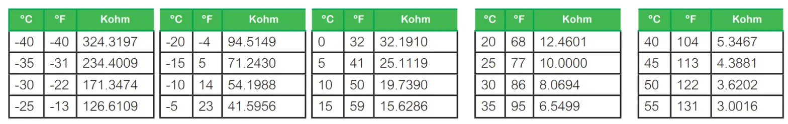
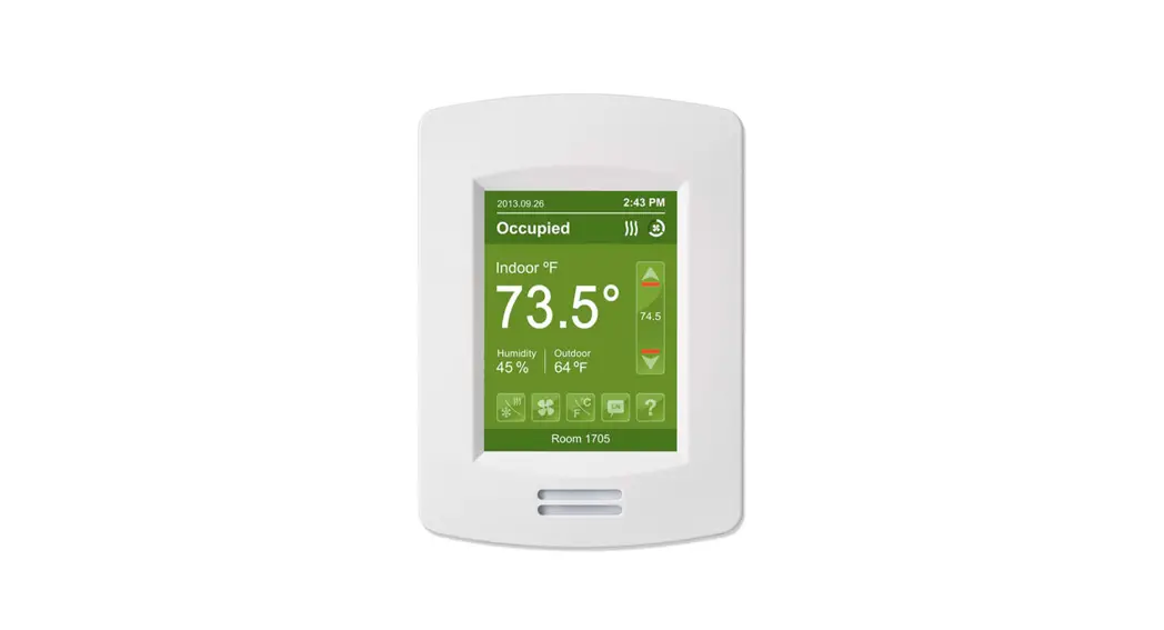
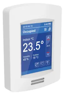
HOME SCREEN DISPLAY
Hospitality User Interface Shown
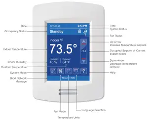
NOTE: User HMI is configurable and allows display functions such as Date, Time, Humidity, Outdoor Temperature, Setpoint, and others to be enabled or disabled by setting various parameters.
HOW TO ENTER SET-UP SCREEN
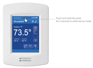
NOTE: If a configuration/installer password is activated to prevent unauthorized access to the configuration menu parameters, a password entry prompt shows to prevent access to the device configuration components.
For more information on using and configuring the functions of the HMI, refer to the VT8350 User Interface Guide
SET-UP SCREEN DISPLAY
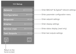
General Note:

APPENDIX A. TERMINAL CORRESPONDENCE
The terminals of a VT8350 are identified differently and have a wider range of possible functions compared to those of any of the VT7000 Room Controllers. Nonetheless, there is a direct correspondence of functions between the terminals of the VT7000 and the VT8350. Consult the table below to verify the appropriate term when replacing a VT7000 Room Controller with a VT8350 Room Controller.
| VT7000 | VT8350 | ||
| Terminal name | Terminal ID | Terminal name | Terminal ID |
| Binary Input 1 | BI1 | Universal Input 16 | UI16 |
| Binary Input 2 | BI2 | Universal Input 17 | UI17 |
| Universal Input 3 | UI3 | Universal Input 19 | UI19 |
| Sensor Common | Scam | Terminal 18 Common | COM |
| Remote Sensor | RS | Universal Input 20 | UI20 – RS |
| Sensor Common | Scam | Terminal 21 Common | COM |
| Mix/Supply Sensor | MS | Universal Input 22 | UI22 – SS |
APPENDIX B. POWER OUTAGE CLOCK RESET
In the event of a power outage, VT8350 Room Controllers retain the correct time as long as the duration of the power outage is not prolonged. Depending on the duration of the power outage, the Room Controllers’ internal clock may need to be updated or reset completely. The following table indicates the expected clock performance after a power outage of a given duration.
| Outage duration | Room Controller behavior |
| 0 – 24 hours | Clock functions are normal |
| 24 – 36 hours | Clock accuracy is not guaranteed, time may need to be adjusted |
| 36 – 72 hours | The clock no longer increments and will need to be adjusted when power is restored. |
| 72+ hours | Clock functions are fully reset and will need to be reinitialized as per a new installation. |
APPENDIX C. DEPLOYMENT
The placement of the Room Controller must be given consideration. It is recommended to install the Room Controller as close to a door as possible (without being blocked by the door), or in an area with high occupant movement.
Ideally, the Room Controller should be installed 5 feet (1.5 meters) above the floor surface to ensure maximum detection range is achieved. As well, Room Controller placement should ensure the occupant crosses the lens beam in a perpendicular path within the prescribed detection zone.
C.1 EXAMPLE OF RECOMMENDED DEPLOYMENT
The below shows Room Controllers installed in ideal locations for two rooms.
The examination room shows one Room Controller installed adjacent to the door. In this area of the room, occupant traffic is high and ensures the occupant will almost always cross the PIR detection path laterally and within the detection range.
The waiting room shows one Room Controller installed beside a door in the middle of the room. As shown in the diagram below, occupant traffic is high in several areas of the room including the entrance, waiting room, access to the door, and activity around the reception desk.
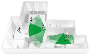 Recommended Installation
C.2 EXAMPLE OF NON-RECOMMENDED DEPLOYMENT
The below shows four Room Controllers (two for each room) installed in non-ideal locations for the two rooms.
The examination room shows one Room Controller installed in a low traffic area near the door, and a second Room Controller installed on the wall directly opposite the door. For the Room Controller installed in the corner wall, the PIR could be blocked by the opened door, while occupant traffic could also be minimal in this area of the room. For the second Room Controller installed opposite the door, the PIR detection could fall outside the specified detection zone, while at the same time most occupant movement would not be lateral to the PIR, thereby not respecting optimal crossing patterns for PIR detection.
The waiting room shows one Room Controller installed in the corner of the room, and a second Room Controller installed beside the reception area. For the Room Controller installed in the corner, the opening/closing of the door creates a high probability that the PIR would get blocked, and therefore, occupancy going undetected. For the Room Controller installed beside the reception area, occupant traffic could fall outside the detection zone, and the receptionist would often be below the 5-foot recommended installation height for the Room Controller.

Non-Recommended Installation
C.3 ROOM CONTROLLER PIR SENSOR DETAILS
The internal Room Controller PIR sensor only detects lateral movement. It cannot detect movement when a person is moving toward it.
It will not detect someone seating on a chair and/or lying on the bed.
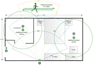
C.4 RECOMMENDATIONS FOR INSTALLATIONS
- Install the Room Controller to cover the more lateral movement.
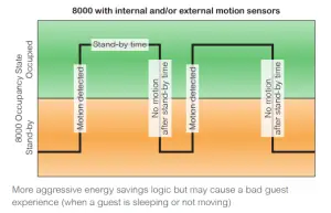
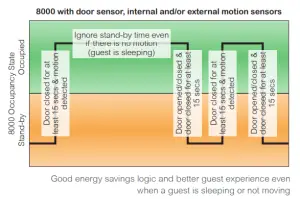
- Install a door sensor, the internal Room Controller occupancy logic works better with a door sensor. Once a motion is detected after a door is opened, the room stays in an occupied state until the door is opened again which puts the Room Controller in stand-by mode and if there is a motion then it goes back in occupied mode. It is also recommended to disable the unoccupied mode, set the “unoccupied time” to 0, so there are only 2 modes in the Room Controller: stand-by and occupied for a standalone solution. Please refer to the two(2) diagrams below for the Room Controller internal occupancy states transition.


- Install additional motion sensors in the bathroom.
- Install additional motion sensors for better motion detection in the entire room.
C.5 ENERGY SAVINGS
PIR can maximize your energy saving from 10-30% by adjusting temperature set points in unoccupied zones during scheduled periods.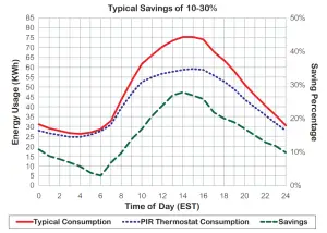
APPENDIX D. CALIFORNIA PROPOSITION 65 WARNING STATEMENT FOR CALIFORNIA RESIDENTSWARNING: This product can expose you to chemicals including Lead, which is known to the State of California to cause cancer and birth defects or other reproductive harm, and Bisphenol A (BPA), which is known to the State of California to cause birth defects or other reproductive harm. For more information, go to www.P65Warnings.ca.gov.
![]() 028-0429-13_II-VT8350-2.4_EN
028-0429-13_II-VT8350-2.4_EN
www.viconics.com
March 2021

 Unit Room Controllers Installation Guide")


 Installation Guide")


