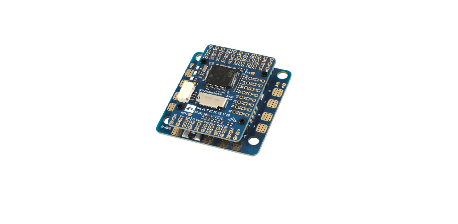
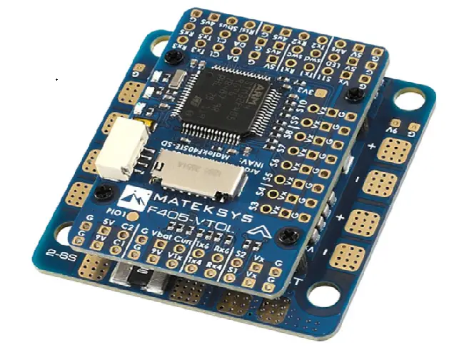
MATEKSYS F405-VTOL Flight Controller
LAYOUT
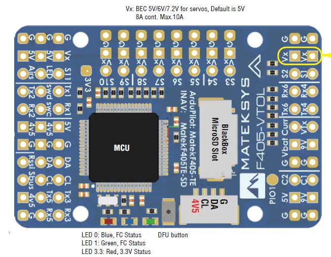
- AirS: Analog Airspeed sensor (0~3.3V) no voltage divider built-in
Rssi: Analog RSSI ADC, 0~3.3V - Tx1/Rx1: UART1_Tx/Rx
- swd/swc: STM32F405RGT6 debug pin
- Rx2: UART2-RX for Serial_RX by default
- PPM is not supported by INAV
- Tx2: UART2-TX
- softserial1_tx is an alternative on Tx2 pad in INAV
- Sbus: UART2_RX + inverter for SBUS receiver
- Tx3/Rx3: UART3_Tx/Rx
- Tx5/Rx5: UART5_Tx/Rx
- DA & CL: I2C_SDA, SCL,
- for compass/digital Airspeed
- 5V: onboard BEC 5V 2A cont.
- 5V is not supplied by USB
- 4V5: 4.4~4.8V, Max.800mA,
- 4V5 is also supplied when connecting via USB.
- G: Ground
DO NOT connect the ESC BEC output (Red wire in the middle of connector) to Vx pad If Vx rail is powered from bottom PDB.
- TX6/RX6: UART6_Tx/Rx
- TX4/RX4: UART4_Tx/Rx
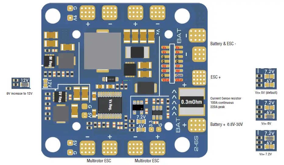
- Vbat: Battery voltage
- onboard battery voltage sense: BATT_VOLT_PIN 14, BATT_VOLT_MULT 21 INAV scale 2100
- Curr: Current signal (0~3.3V)
- onboard current sense: BATT_CURR_PIN 15, BATT_AMP_PERVLT 66.7 INAV scale 150
- 9V: onboard BEC 5V 2A cont. Max.3A
- 9V will increase to 12V if “12V” jumper on bottom PDB is bridged.
- 5V: onboard BEC 5V 2A cont. Max.3A
- G: Ground
- VTx: Video OUT for Video Transmitter
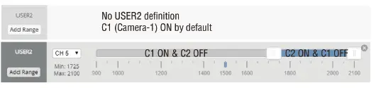
- C1: Camera-1 video IN (Default)
- C2: Camera-2 video IN
- C1/C2 can be switched via ArduPilot Relay or Modes/USER2 (INAV)
- Two cameras should be set with identical video format, both PAL or both NTSC
- PIO1: Low/High level switchable via INAV Modes/USER1 or ArduPilot Relay
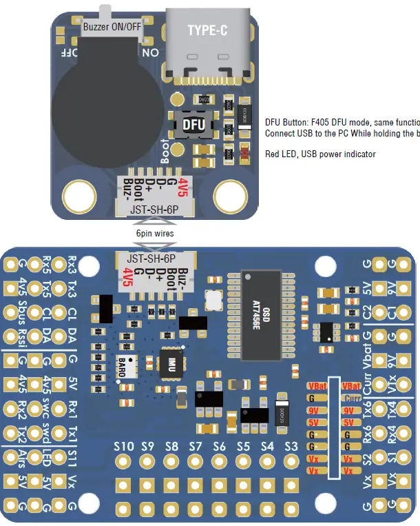
- DFU Button: F405 DFU mode, same function as the button on FC board.
- Connect USB to the PC While holding the boot button in.
- Red LED, USB power indicator
| INAV AirPlane | INAV Multirotor | ArduPilot | |
| S1 | Motor | Motor | PWM1 |
| S2 | Motor | Motor | PWM2 |
| S3 | Servo | Motor | PWM3 |
| S4 | Servo | Motor | PWM4 |
| S5 | Servo | Motor | PWM5 |
| S6 | Servo | Motor | PWM6 |
| S7 | Servo | Motor | PWM7 |
| S8 | Servo | Motor | PWM8 |
| S9 | Servo | Servo | PWM9 |
| S10 | Servo | Servo | PWM10 |
| S11 | Servo | Servo | PWM11 |
| LED | 2812 LED | 2812 LED | PWM12 |
- Top FC board: 44x29mm, Holes: 25mm-Φ2mm
- Bottom PDB: 45x42mm, Holes: 25mm-Φ2mm, 35mm-Φ4mm
- Weight: 25g w/ USB externder
Multirotor ESC
Wiring
ArduPlane fw: MATEKF405-TE
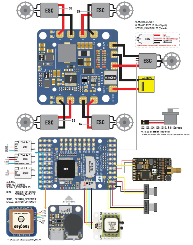
INAV fw: MATEKF405TE_SD
- INAV doesn’t support VTOL, F405-VTOL can be used as a normal fixed-wing flight controller
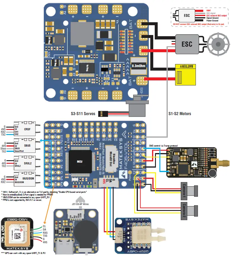
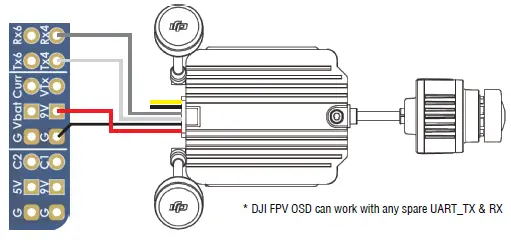
- DJI FPV OSD can work with any spare UART_TX & RX
I/O Mapping
| ArduPilot | |||||
|
PWM 5V tolerant I/O | S1 | PWM1 GPIO50 | TIM8_CH4 | DMA/DShot | Group1 |
| S2 | PWM2 GPIO51 | TIM8_CH3 | DMA/DShot | ||
| S3 | PWM3 GPIO52 | TIM1_CH3N | DMA/DShot | Group2 | |
| S4 | PWM4 GPIO53 | TIM1_CH1 | DMA/DShot | ||
| S5 | PWM5 GPIO54 | TIM2_CH4 | DMA/DShot | Gourp3 | |
| S6 | PWM6 GPIO55 | TIM2_CH3 | DMA/DShot | ||
| S7 | PWM7 GPIO56 | TIM2_CH2 | DMA/DShot | ||
| S8 | PWM8 GPIO57 | TIM2_CH1 | DMA/DShot | ||
| S9 | PWM9 GPIO58 | TIM12_CH1 | NO DMA | Gourp4 | |
| S10 | PWM10 GPIO59 | TIM13_CH1 | NO DMA | Gourp5 | |
| S11 | PWM11 GPIO60 | TIM4_CH1 | NO DMA | Gourp6 | |
| LED pad | PWM12 GPIO61 | TIM3_CH4 | DMA/DShot | Gourp7 | |
| SERVO12_FUNCTION 120, NTF_LED_TYPES neopixel | |||||
| Mixing Dshot and normal PWM operation for outputs is restricted into groups, ie. enabling Dshot for an output in a group requires that ALL outputs in that group be configured and used as Dshot, rather than PWM outputs. If servo and motor are mixed in same group, make sure this group run lowest PWM frequency according to the servo specification. ie. Servo supports Max. 50Hz, ESC must run at 50Hz in this group. | |||||
|
ADC | Vbat Pad | 1K:20K divider builtin 0~30V | Vbat ADC onboard battery voltage | BATT_VOLT_PIN BATT_VOLT_MULT | 14 21.0 |
| Curr pad | 0~3.3V | current sensor ADC onboard current sense | BATT_CURR_PIN BATT_AMP_PERVLT | 15 66.7 | |
| RSSI Pad | 0~3.3V | RSSI ADC Analog RSSI | RSSI_ANA_PIN RSSI_TYPE | 8 2 | |
| AirS /PC0 Pad | no divider builtin 0~3.3V | AirS ADC Analog Airspeed | ARSPD_PIN ARSPD_TYPE | 10 2 | |
|
I2C |
I2C1 |
5V tolerant I/O | Compass | COMPASS_AUTODEC | 1 |
| onboard Baro SPL06-001 | Address | 0x76 | |||
| Digital Airspeed I2C MS4525 DLVR-L10D | ARSPD_BUS ARSPD_TYPE ARSPD_TYPE | 1 1 9 | |||
|
UART 5V tolerant I/O | USB | USB | console | SERIAL0 | |
| TX1 RX1 | USART1 | with DMA | telem1 | SERIAL1 | |
| TX3 RX3 | USART3 | NO DMA | telem2 | SERIAL2 | |
| TX5 RX5 | UART5 | NO DMA | GPS1 | SERIAL3 | |
| TX4 RX4 | UART4 | NO DMA | GPS2/DJI OSD | SERIAL4 | |
| TX6 RX6 | USART6 | TX6 with DMA | USER | SERIAL5 | |
|
TX2 RX2 SBUS | USART2 | with DMA | RC input/Receiver | SERIAL6 | |
| RX2 | IBUS/DSM/PPM | BRD_ALT_CONFIG 0 Default | |||
| Sbus pad | SBUS | ||||
| TX2 & RX2 | CRSF | BRD_ALT_CONFIG 1 SERIAL6_PROTOCOL 23 | SERIAL6_OPTIONS 0 | ||
| TX2 | uninverted FPort (hacked) | SERIAL6_OPTIONS 4 | |||
| TX2 | SRXL2 | SERIAL6_OPTIONS 4 | |||
| INAV | INAV MultiRotor | INAV Plane | |||
|
PWM | S1 | 5 V tolerant I/O | TIM8_CH4 | Motor | Motor |
| S2 | 5 V tolerant I/O | TIM8_CH3 | Motor | Motor | |
| S3 | 5 V tolerant I/O | TIM1_CH3N | Motor | Servo | |
| S4 | 5 V tolerant I/O | TIM1_CH1 | Motor | Servo | |
| S5 | 5 V tolerant I/O | TIM2_CH4 | Motor | Servo | |
| S6 | 5 V tolerant I/O | TIM2_CH3 | Motor | Servo | |
| S7 | 5 V tolerant I/O | TIM2_CH2 | Motor | Servo | |
| S8 | 5 V tolerant I/O | TIM2_CH1 | Motor | Servo | |
| S9 | 5 V tolerant I/O | TIM12_CH1 | Servo | Servo | |
| S10 | 5 V tolerant I/O | TIM13_CH1 | Servo | Servo | |
| S11 | 5 V tolerant I/O | TIM4_CH1 | Servo | Servo | |
| LED | 5 V tolerant I/O | TIM3_CH4 | 2812LED | 2812LED | |
|
ADC | Vbat Pad | 1K:20K divider builtin 0~30V | Vbat ADC ADC_CHANNEL_1 | BF scale 210, INAV scale 2100 | |
| Curr pad | 0~3.3V | Current ADC ADC_CHANNEL_2 | scale 150 | ||
| RSSI Pad | 0~3.3V | RSSI ADC ADC_CHANNEL_3 | Analog RSSI | ||
| AirS /PC0 Pad | no divider builtin 0~3.3V | AirS ADC ADC_CHANNEL_4 | Analog Airspeed | ||
|
I2C |
I2C1 |
5V tolerant I/O | Compass | QMC5883 / HMC5883 / MAG3110 / LIS3MDL | |
| OLED | 0.96″ | ||||
| onboard Barometer | SPL06-001 | ||||
| Digital Airspeed sensor | MS4525 | ||||
| Temperature sensor | |||||
|
UART 5V tolerant I/O | USB | USB | |||
| TX1 RX1 |
5V tolerant I/O | UART1 | USER | ||
| TX3 RX3 | UART3 | USER | |||
| TX4 RX4 | UART4 | USER | |||
| TX5 RX5 | UART5 | USER | |||
| TX6 RX6 | UART6 | USER | |||
|
TX2 RX2 SBUS |
5V tolerant I/O | UART2 | RC input/Receiver | ||
| Sbus pad | for SBUS receiver, Sbus pad = RX2+inverter | ||||
| RX2 pad | IBUS/DSM | ||||
| TX2 & RX2 | CRSF | ||||
| TX2 pad | SmartPort Telemetry | enable Softserial_Tx1 | |||
| TX2 pad | uninverted FPort (hacked) | ||||
| TX2 pad | SRXL2 | ||||


