sooplanet ASW Series Inverter
Safety Instruction
- The contents of this document will be updated irregularly for product version upgrade or other reasons.Un less otherwise specified, this document only works as guide. All statements, information and suggestions in this document do not constitute any guarantee.
- This product can only be installed, commissioned, operated and maintained by technicians who have carefully read and fully understood the user manual.
- This product must only be connected with PV modules of protection class II( in accordance with lEC 61730, application class A).PV modules with a high capacitance to ground must only be used if their capacity does not exceed 1.5µF.Do not connect any sources of energy other than PV modules to the product.
- The product must only be operated in connection with an intrinsically safe lithium-ion battery approved by AISWEI. The battery must comply with the locally applicable standards and directives and must be intrinsically safe.
- The communication interface of the battery used must be compatible with the product. The entire battery voltage range must be completely within the permissible input voltage range of the product. The maximum permissible DC input voltage of the product must not be exceeded.
- The PV modules generate dangerous high DC voltage which is present in the DC cable conductors and live components. The DC cables connected to a battery may be live. Touching live DC cable conductors and live components can result in lethal injuries due to electric shock.
- All components must remain within their permitted operating ranges at all times.
Mounting environment
- Ensure that the inverter is installed out of the reach of children.
- To ensure best operating status and prolonged service life, the mounting ambient temperature of the inverter should be 45°C.
- To avoid direct sunlight, rain, snow, ponding on the inverter, it is suggested to mount the inverter in places with a top protective roof.
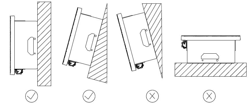
Do not completely cover the top of the inverter. - The mounting condition must be suitable for the weight and size of the inverter. The inverter is suitable to be mounted on solid wall that is vertical or tilted backwards (Max.15°). It is not recommended to install the inverter on the wall made of plasterboards or similar materials. The inverter may make noise when working.

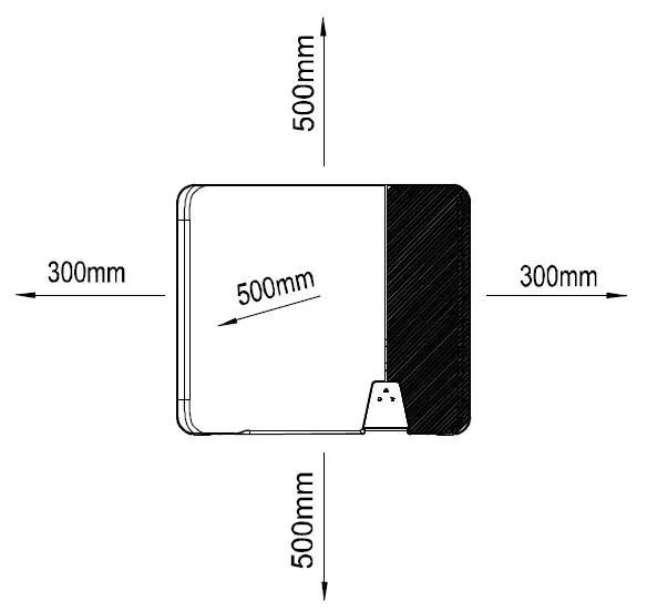
- To ensure adequate heat dissipation, the clearances between the inverter and other objects are recommended as right:
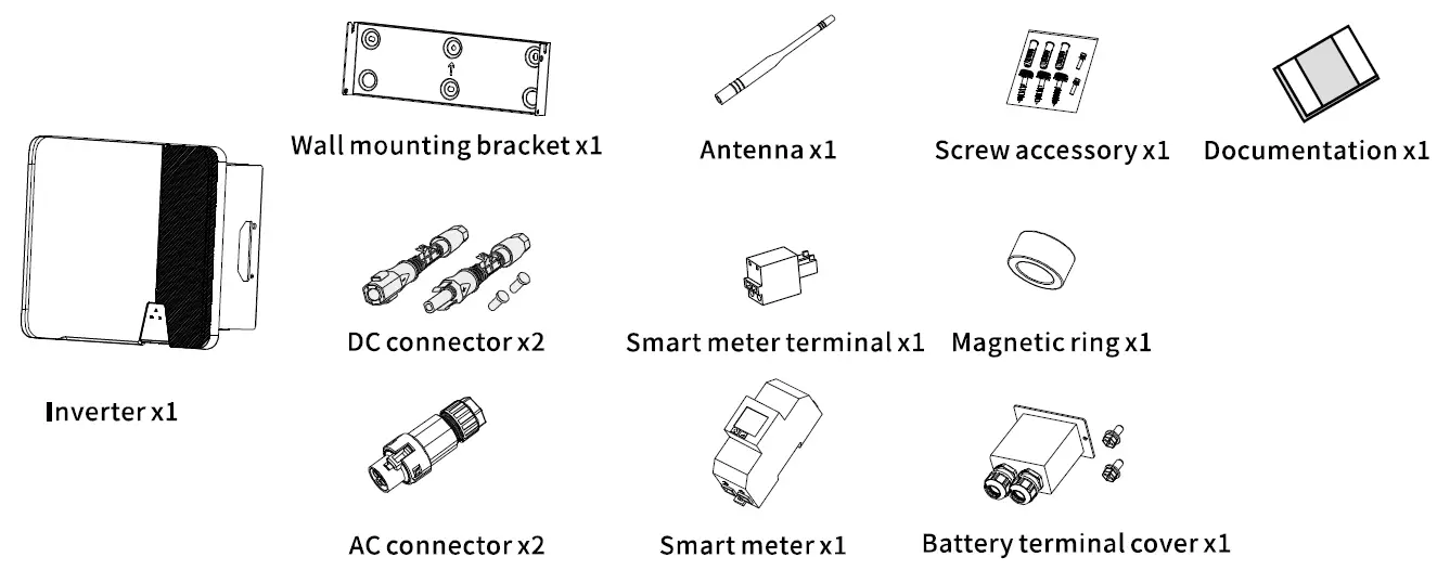
Scope of delivery
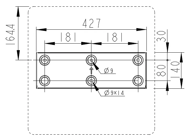
Inverter’s mounting
- Use a <l>lOmm bit to drill 3 holes at a depth of about 70mm according to the location of the wall mounting bracket.

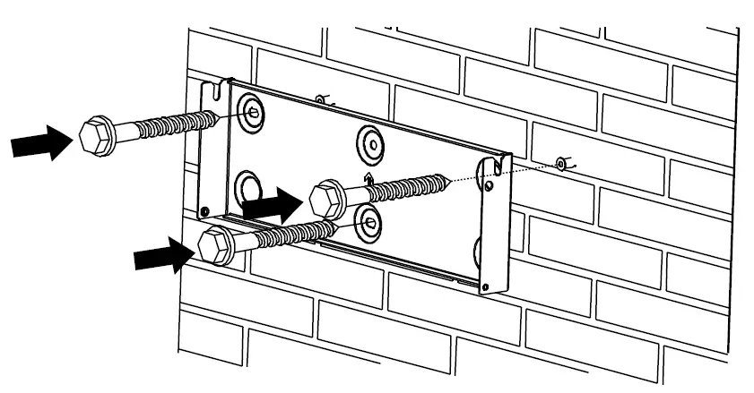
- Insert wall plugs into the wall and fix the wall mounting bracket to the wall by screwing three self-tapping screws(SWlO).

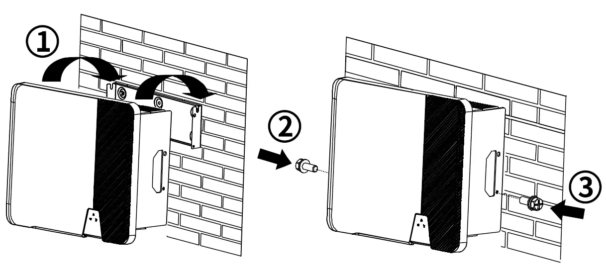
- Hang the inverter to the wall mounting bracket. Secure the inverter to the wall mounting bracket on both sides using MS screws.
Screwdriver type: PH2, torque: 2.5Nm.
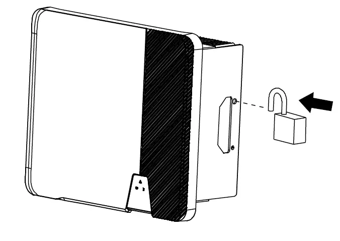
- To protect the inverter from theft, attach the padlock provided by customer through the wall mounting bracket and the inverter.
DC connection
- Make sure PV modules have good insulation against ground.
- On the coldest day based on statistical records, the Max. open-circuit voltage of the PV modules must not exceed the Max. input voltage of the inverter.
- Check the polarity of DC cables.
- Ensure that DC switch has been disconnected.
- Do not disconnect DC connectors under load.
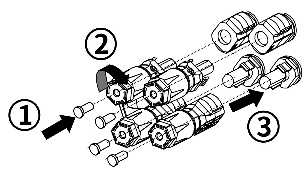
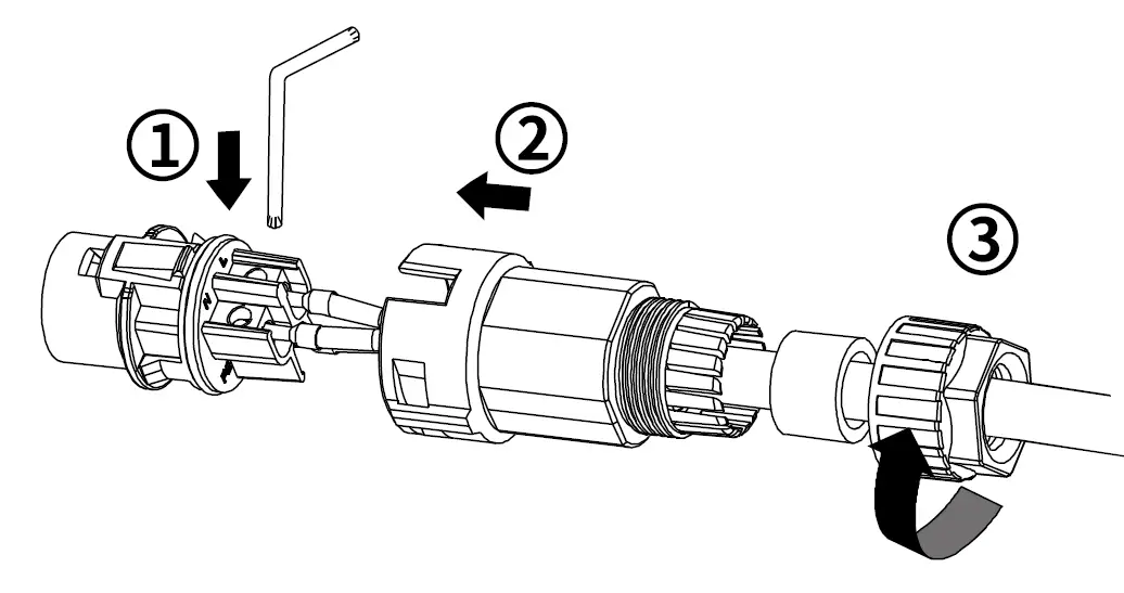
- Please refer to “DC Connector Installation Guide”.
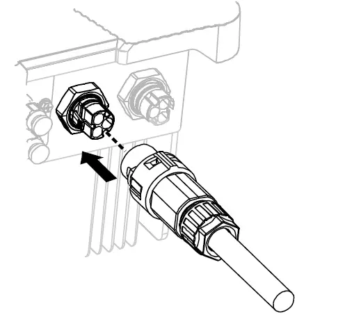
- Before DC connection, insert the DC plug connectors with sealing plugs into DC input connectors of the inverter to ensure protection degree.
Battery connection
- The lithium battery (pack) capacity should be S0Ah or larger.
- Lead acid batteries are not allowed.
- The battery type must be approved by AISWEI.
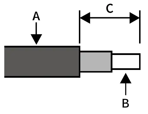
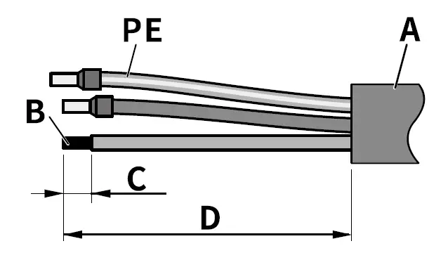
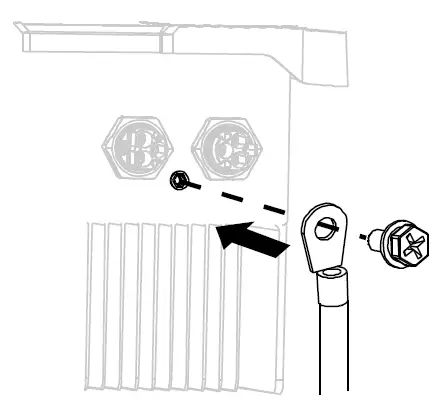
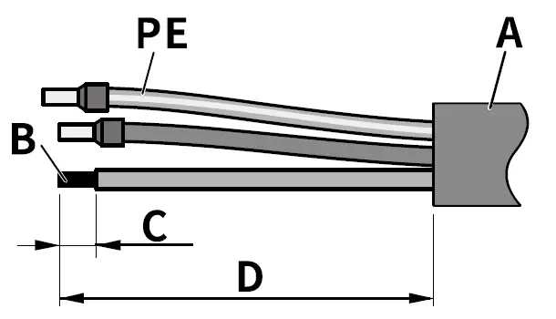
- Cable requirements are as follows. Insert the conductor into a suitable terminal lug and crimp the contact .

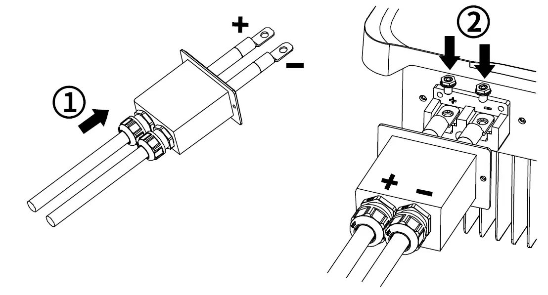
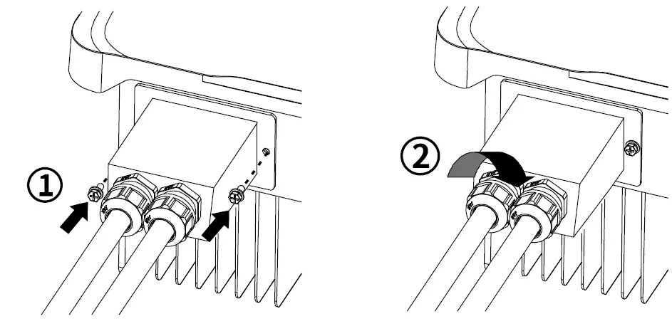
Object Description Value A External diameter 10-12mm B Copper conductor cross-section 20-25mm2 C Stripping length of the cable outer sheath ::555mm - Screw the cable terminal lugs to the socket through the battery terminal cover .
Screwdriver type: T30 or SWl0, torque: 4.0Nm
- Tighten the battery terminal cover and cable gland nuts.
Screwdriver type: PH2, torque: 1.6Nm
AC connection
DANGER
- All electrical installations must be done in accordance with all local and national rules.
- Make sure that all DC switches and AC circuit breakers have been disconnected before establishing electrical connection. Otherwise, the high voltage within the inverter may lead to electrical shock.
- In accordance with safety regulations, the inverter need be grounded firmly. When poor ground connection (PE) occurs, the inverter will report PE grounding error. Please check and ensure that the inverter is grounded firmly or contactAISWEI service.
- AC cable requirements are as follows. Insert the conductor into a suitable ferrule acc. to DIN 46228-4 and crimp the contact .

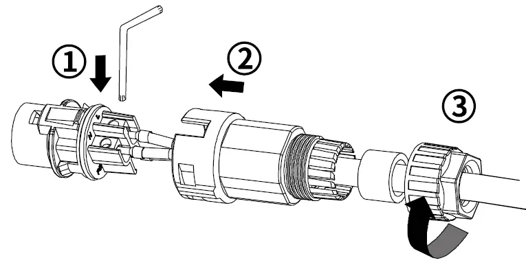
Object Description Value A External diameter 10-16mm B Copper conductor cross-section 4-6mm 2 C Stripping length of the insulated conductors 13mm D Stripping length of the cable outer sheath 53mm The PE conductor must be 2 mm longer than the Land N conductors. - Loosen the swivel nut of AC connector. Insert the crimped conductors into corresponding terminals and tighten screws with the accompanied wrench tool ( Torque: 1.4N m). Insert the adapter to the socket element, stuff the sealing sleeve into the adapter and tighten the swivel nut.

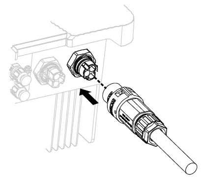
- Plug the AC connector into the socket for the AC connection.

- If required, you can connect a second protective conductor as equipotential bonding.
| Object | Explanation |
| M4Xl0screw | Screwdrivertype: PH2, torque : l.6Nm |
| Terminal lug | Type: M4 , Customer provided |
| Grounding cable | Copper conductor cross-section: 4-6mm 2 |
EPS connection
DANGER
- All electrical installations must be done in accordance with all local and national rules.
- Make sure that all DC switches and AC circuit breakers have been disconnected before establishing electrical connection. Otherwise, the high voltage within the inverter may lead to electrical shock.
- In accordance with safety regulations, the inverter need be grounded firmly. When poor ground connection (PE) occurs, the inverter will report PE grounding error. Please check and ensure that the inverter is grounded firmly or contactAISWEI service.
- AC cable requirements are as follows. Insert the conductor into a suitable ferrule acc. to DIN 46228-4 and crimp the contact .

Object Description Value A External diameter 10-16mm B Copper conductor cross-section 2.5-6m m2 C Stripping length of the insulated conductors 13mm D Stripping length of the cable outer sheath 53mm The PE conductor must be 2 mm longer than the Land N conductors. - Loosen the swivel nut of AC connector. Insert the crimped conductors into corresponding terminals and tighten screws with the accompanied wrench tool ( Torque: l.4Nm). Insert the adapter to the socket element, stuff the sealing sleeve into the adapter and tighten the swivel nut.

- Plug the AC connector into the socket for the EPS connection.
Smart meter connection
DANGER
- For outdoor use, the communication cables must be UV-resistant.
- Make sure AC cable is totally isolated from AC power before connecting.
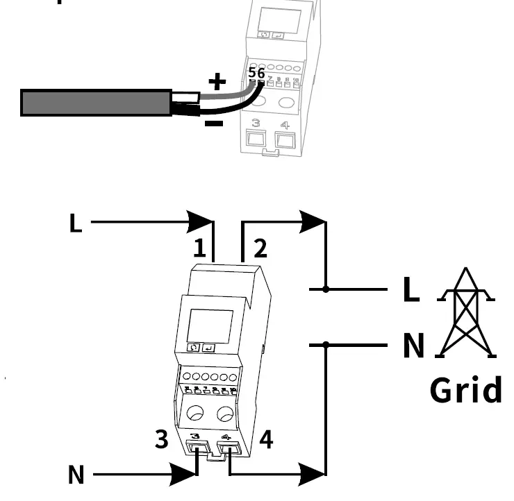
Connection diagram
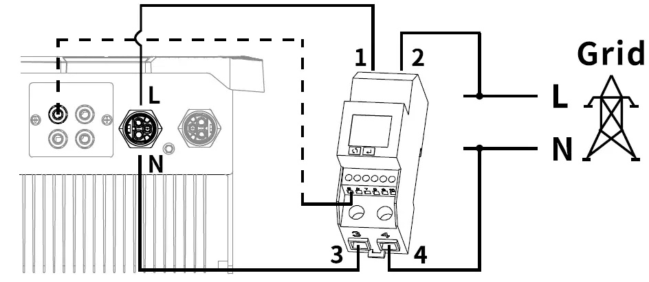
Smart meter communication
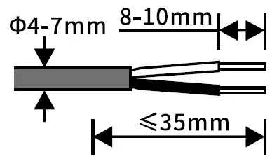
- Cable requirements are as follows.
Insert the conductor into a suitable ferrule acc. to DIN 46228-4 and crimp the contact.
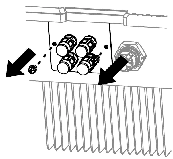
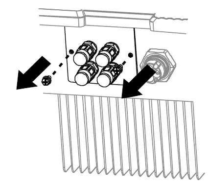
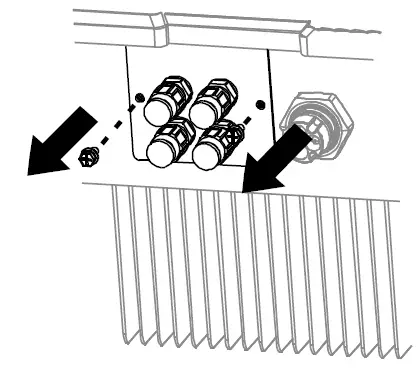
- Remove the communication plate.

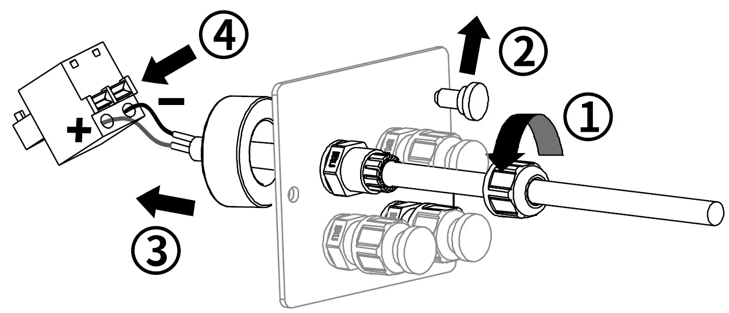
- Loosen the swivel nut of the cable gland on the communication plate, remove the sealing plug and lead
the stripped cable through the swivel nut, sealing sleeve, communication plate and magnetic ring, press the latch of the smart meter terminal and insert the conductors accordingly. Make sure the cable is connected firmly.
- Insert the smart meter terminal to the socket, screw communication plate to the inverter and tighten the swivel nut.
Screwdriver type: PH2, torque: 1.6Nm - Insert the other end cable conductors into the slots of smart meter and tighten them. Screwdriver type: PHO, 0.7Nm
AC cable connection
- Insert the other end cable conductors of AC connector into suitable ferrules acc. to DIN 46228-4 and crimp the contacts.
- Insert conductors into the slots of smart meter and tighten them as right. Screwdriver type: PH2, torque: 1.6Nm
Communication setup
- Separate communication cables from power cables and serious interference sources.
- The communication cables must be CAT-SE or higher-level shield cables. Pin assignment complies with ElA/TlA568B standard. For outdoor use, the communication cables must be UV-resistant. The total length of communication cable cannot exceed 1000m.
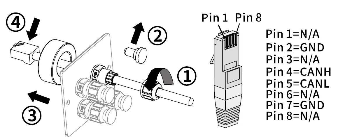
BMS communication
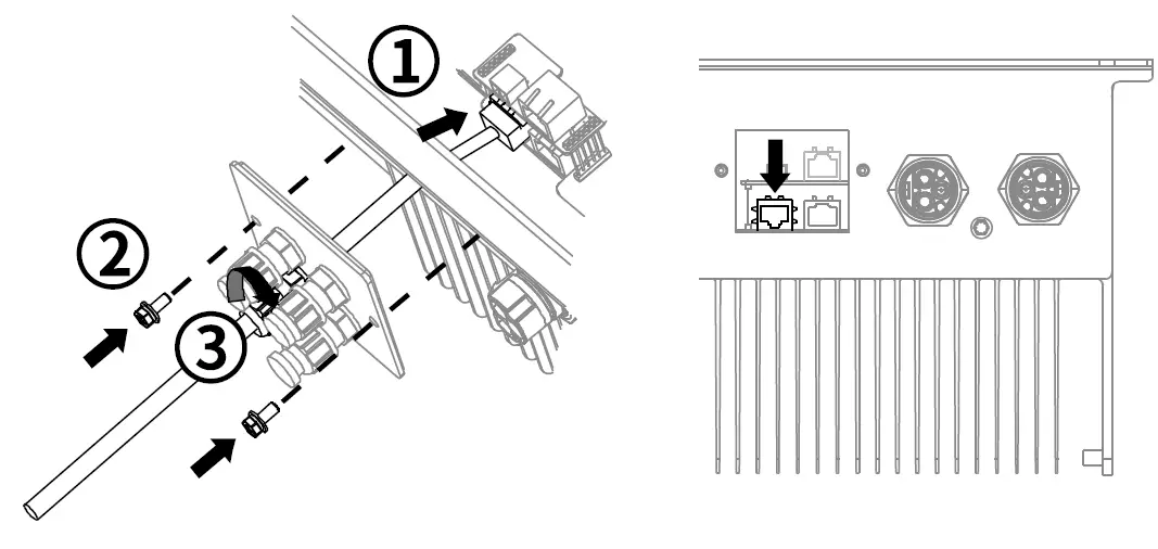
- Remove the communication plate.

- Loosen the swivel nut of the cable gland on the communication plate, remove the sealing plug and lead the stripped cable through the swivel nut, sealing sleeve, communication plate and magnetic ring, crimp the crystal as below pin assignment.

- Insert the cystal to the socket, screw communication plate to the inverter and tighten the swivel nut. Screwdriver type: PH2, torque: 1.6Nm
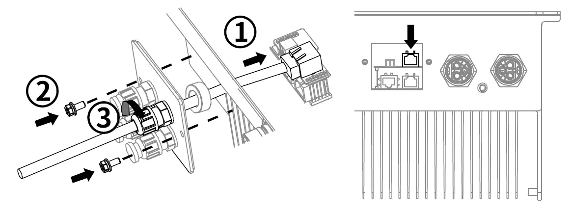
DRED
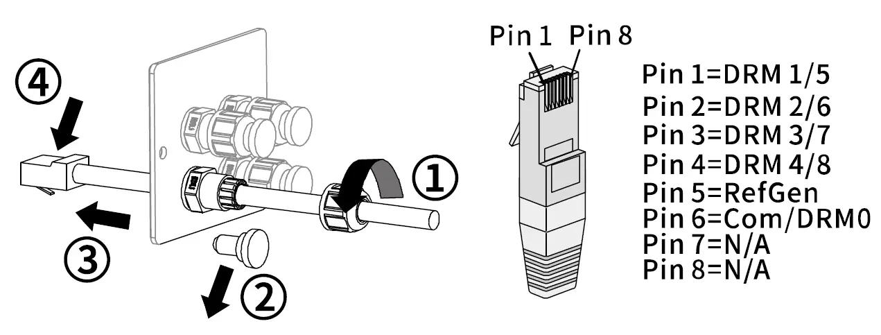
- Remove the communication plate.

- Loosen the swivel nut of the cable gland on the communication plate, remove the sealing plug and lead the cable through the swivel nut, sealing sleeve, communication plate , crimp the crystal as below pin assignment.

- Insert the cystal to the socket, screw communication plate to the inverter and tighten the swivel nut. Screwdriver type: PH2, torque: 1.6Nm
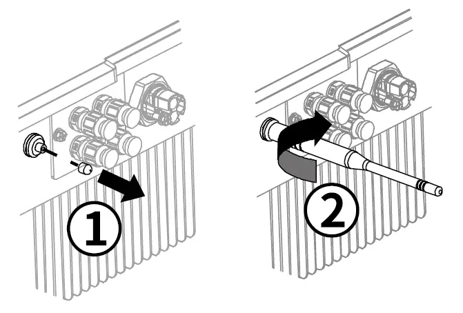
WiFi
Take off the sealing cap and tighten the antenna to inverter.
 Commissioning
Notice
- Check that the inverter is grounded reliably.
- Check that the ventilation condition surrounding the inverter is good.
- Check that the grid voltage at the point of connection of the inverter is within the permitted range.
- Check that the sealing plugs in DC connectors and communication cable glands are sealed tightly.
- Check that grid/battery connection regulations and other parameter settings meet safety requirements.
- Check the correct communication connection between the battery BMS and the inverter.
- Check the correct communication connection between the smart meter and the inverter.
- Switch on AC circuit breaker between the inverter and the grid.
- Switch on DC switch.
- Switch on battery.
- Link to inverter WiFi.
- Set the communication parameters of the smart meter.
- Set parameters through App (Safety, Smart meter, Battery, Working-mode).
- Click power-on button through App, Energy storage inverter will start to work.
EU Declaration of Conformity
Within the scope of the EU directives:
- Electromagnetic compatibility 2014/30/EU (L 96/79-106 , March 29, 2014)(EMC)
- Low voltage directive 2014/35/EU (L 96/357-374 , March 29, 2014)(LVD)
- Radio equipment directive 2014/53/EU (L 153/62-106 , May 22, 2014)(RED)
AISWEI New Energy Technology (Jiangsu) Co., Ltd. confirms herewith that the inverters mentioned in this document are in compliance with the fundamental requirements and other relevant provisions of the above-mentioned directives.
The entire EU Declaration of Conformity can be found at www.aiswei-tech.com
Technical Data
| Technical Data | Asw 3000H-s | ASW36BOH-s I | ASW4000H-s | I | Asw sooo H-s |
| PV input port | |||||
| Max. PV modules power(STC) | 5500W | 6180W | 6500W | 7500W | |
| Max . PV input voltage | d.c. 550V | ||||
| MPPTvoltage range | d.c. 100-530V | ||||
| Max. PV input current | d.c. 2 X l 2A | ||||
| lsc PV (absolute maximum) | d .c. 2 X l 8A | ||||
| Max. PV input current , per MPPT | d .c . 12A | ||||
| Number of MPPT/strings per MPPT | 2/ 1 | ||||
| Battery input port | I | ||||
| Rated Battery voltage | d . c. 48V | ||||
| Battery voltage range | d . c. 40-60V | ||||
| Ma x. battery charge/ discharge current | d.c. 50 / 50A | ||||
| Battery type | Li-Ion | ||||
| Grid output/input port | |||||
| Rated grid active power | 3000W | 3680W | 4000W | 5000W | |
| Max. grid output apparent power | 3000VA ” | 3680VA’ ‘ | 4000VA’ ‘ | 5000VA’ ”’ | |
| Rated grid voltage | a.c. 230V | ||||
| Rat ed grid frequency | 50Hz | ||||
| Max. grid output current | a.c 13.6A I | a.c 16A I | a.c 18 .2A | I | a.c 22.7A”‘ |
| Max. grid input apparent power | 2500VA “‘ | ||||
| Max. grid input current | a.c. 12A | ||||
| Adjustable displacement power factor | 0.8 ind… 0.8 cap | ||||
| Harmonic distortion (THO) at Pac.r | < 3% | ||||
| EPS output port | |||||
| Rated EPS voltage | a.c. 230V | ||||
| Rat ed EPS frequency | 50Hz | ||||
| Max . EPS output apparent power | 2500VA’ ‘ | ||||
| Max . EPS output current | a.c. 12A | ||||
| General Data | |||||
| Dim ensi ons (W x H x D) | 494X420X 195mm | ||||
| Weight | 21.5kg | ||||
| Noise emission (typical) | < 25dB( A) @l m | ||||
| DC connection | Plug-in DC connector | ||||
| AC connection | Plug-in AC connect or | ||||
| Communi cation | WiFi /Meter | ||||
| Display | LED | ||||
| *1: For VDE- AR-N4105 ,Sma x=460 0VA *2 For AS / NZS 4777.2:2015, Sma x=Srat ed *3 For AS / NZS4777.2:2015, lac ma x=21.7A | |||||
| Technical Data | ASW3000H-S I ASW3680H-S I ASW4000H-S I ASWS000H-S |
| General Data | |
| Mounting | Wall bracket mounting |
| Cooling | Convection |
| Operating temperature range | -25… +G0′ C |
| Relative humidity (non-condensing) | 0… 100% |
| Max. operating altitude | 4000m(Derating above 3000m ) |
| Degree of protection | IP65 |
| Climate category | 4K4H |
| Inverter topology | Non-isolated |
| Protective class | |
| Overvoltage category | ll( PV) , lll(MAINS) |
Contact
If you have any technical problems with our products, please contact our service. We require the following information in order to provide you with the necessary assistance:
- Inverter device type
- Inverter serial number
- Battery type
- Type and number of connected PV modules
- Error code
- Mounting location
- Warranty card
AISWEI New Energy Technology(Jiangsu)Co., Ltd.
Hotline: +86 400 801 9996 (Mainland)
+886 809 089 212 (Taiwan)
Service email: [email protected]
Web: www.aiswei-tech.com
Add.: No. 198 Xiangyang Road, Suzhou 215011, China
AISWEI Pty Ltd.
Hotline: +61 390 988 673
Service email: [email protected]
Add.: Level 40,140 William Street, Melbourne VIC 3000, Australia
AISWEI B.V.
Hotline: +31 208 004 844 (Netherlands)
+48 134 926 109 (Poland)
Service email: [email protected]
Add.: Barbara Strozzilaan 101, Se etage, kantoornummer 5.12, 1083 HN, Amsterdam, The Netherlands
Rest of the world
Service email: [email protected]


