
![]() ACS480 Inverter Drive
ACS480 Inverter Drive
Installation Guide and start-up guide 
Safety instructions
![]() WARNING! Obey these instructions. If you ignore them, injury or death, or damage to the equipment can occur. If you are not a qualified electrical professional, do not do electrical installation or maintenance work.
WARNING! Obey these instructions. If you ignore them, injury or death, or damage to the equipment can occur. If you are not a qualified electrical professional, do not do electrical installation or maintenance work.
- Do not do work on the drive, motor cable, motor, or control cables when the drive is connected to the input power. Before you start the work, isolate the drive from all dangerous voltage sources and make sure that it is safe to start the work. Always wait for 5 minutes after disconnecting the input power to let the intermediate circuit capacitors discharge.
- Do not do work on the drive when a rotating permanent magnet motor is connected to it. A rotating permanent magnet motor energizes the drive, including its input and output terminals.
Unpack the delivery
Keep the drive in its package until you are ready to install it. After unpacking, protect the drive from dust, debris, and moisture. Make sure that these items are included:
- drive
- assistant control panel
- options, if ordered
- RIIO-01 I/O & EIA-485 module. Note: If a Fieldbus adapter is ordered, it replaces the RIIO-01 module of the standard delivery.
- mounting template (frames R3 and R4 only)
- installation accessories (cable clamps, etc.)
- multilingual warning sticker sheet (residual voltage warning)
- safety instructions
- quick installation and start-up guide
- hardware and firmware manuals, if ordered.
Make sure that there are no signs of damage to the items.
Reform the capacitors
If the drive has not been powered up for a year or more, you must reform the DC link capacitors. The manufacturing date is on the type designation label. Refer to Capacitor reforming instructions (3BFE64059629 [English]).
Select the cables and fuses
- Select the power cables. Obey the local regulations.
• Input power cable: ABB recommends using asymmetrical shielded cable (VFD cable) for the best EMC performance.
• Motor cable: Use symmetrical shielded cable (VFD cable) for the best EMC performance. The symmetrical shielded cable also reduces bearing currents, wear, and stress on motor insulation.
• Power cable types: In IEC installations, use copper or aluminum cables (if permitted). In UL installations, use only copper cables.
• Current rating: max. load current.
• Voltage rating: min. 600 V AC.
• Temperature rating: In IEC installations, select a cable rated for at least 70 °C (158 °F) maximum permissible temperature of the conductor in continuous use. In UL installations, select a cable rated for at least 75 °C (167 °F).
• Size: Refer to Fuses and typical power cable sizes for the typical cable sizes and to Terminal data for the power cables for the maximum cable sizes. - Select the control cables. Use double-shielded twisted-pair cable for analog signals. Use double-shielded or single-shielded cable for the digital, relay, and I/O signals. Do not run 24 V and 115/230 V signals in the same cable.
- Protect the drive and input power cable with the correct fuses. Refer to Fuses and typical power cable sizes.
Examine the installation area
The drive is intended for cabinet installation and has a degree of protection of IP20 / UL open type.
Examine the site where you will install the driver. Make sure that:
- The installation site is sufficiently ventilated and hot air does not recirculate.
- There is sufficient free space around the drive for cooling, maintenance, and operation. For the minimum free space requirements, refer to Free space requirements.
- The ambient conditions meet the requirements. Refer to Ambient conditions.
- The installation surface is as close to vertical as possible and strong enough to support the weight of the drive. Refer to Dimensions and weights.
- The installation surface, floor, and materials near the drive are not flammable.
- There are no sources of strong magnetic fields, such as high-current single-core conductors or contactor coils near the drive. A strong magnetic field can cause interference in the operation of the drive.
Install the drive
You can install the drive with screws or to a DIN rail (top hat type, width × height= 35 mm × 7.5 mm [1.4 in × 0.3 in]).
- Install R0 drives vertically. R0 drives do not have a cooling fan.
- You can install drives with frame size R1…R4 tilted by a maximum of 90 degrees, from vertical to fully horizontal orientation.
- Do not install the drive upside down.
- You can install several drives side by side.
To install the drive with screws
- Make marks on the surface for the mounting holes. Refer to Dimensions and weights. Use the included mounting template for frames R3 and R4.
- Drill the holes for the mounting screws. If necessary, install suitable plugs or anchors into the holes.
- Install the mounting screws into the holes. Leave a gap between the screw head and the installation surface.
- Put the drive onto the mounting screws.
- Tighten the mounting screws.
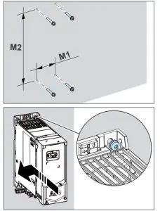
To install the drive to a DIN rail
- Move the locking part to the left. If necessary, use a flat-head screwdriver.
- Push and hold the locking button down.
- Put the top tabs of the drive onto the top edge of the DIN rail.
- Put the drive against the bottom edge of the DIN rail.
- Release the locking button.
- Move the locking part to the right.
- Make sure that the drive is correctly installed.
To remove the drive, open the locking part and lift the drive from the DIN rail.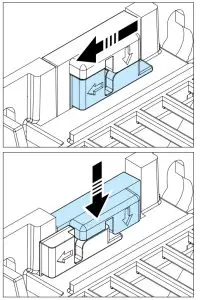
Measure the insulation resistance
Drive: Do not do voltage tolerance or insulation resistance tests on the drive, because this can cause damage to the drive.
Input power cable: Before you connect the input power cable, measure the insulation of the input power cable. Obey the local regulations.
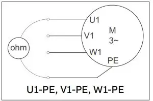
Motor and motor cable:
- Make sure that the motor cable is connected to the motor and disconnected from the drive output terminals T1/U, T2/V and T3/W.
- Use a voltage of 1000 V DC to measure the insulation resistance between each phase conductor and the protective earth conductor. The insulation resistance of an ABB motor must be more than 100 Mohm (at 25 °C [77 °F]). For the insulation resistance of other motors, refer to the manufacturer’s documentation. Moisture in the motor decreases the insulation resistance. If you think that there is moisture in the motor, dry the motor and do the measurement again.

Make sure that the drive is compatible with the grounding system
You can connect all drive types to an asymmetrically grounded TN-S system (center-grounded wye). The drive is delivered with the EMC and VAR screws installed. The material of the screws (plastic or metal) depends on the product variant. The table shows when to remove the metal EMC screw (disconnect the internal EMC filter) or the metal VAR screw (disconnect the varistor circuit).
| Screw label | Factory default screw material | Grounding systems | ||
| Symmetrically grounded TN-S systems (center-grounded wye) | Corner-grounded delta, midpoint grounded delta and TT systems | IT systems (ungrounded or high-resistance grounded) | ||
| EMC | Metal | Do not remove | Remove | Remove |
| Plastic 1) | Do not remove 2) | Do not remove | Do not remove | |
| VAR | Metal | Do not remove | Do not remove | Remove |
| Plastic | Do not remove | Do not remove | Do not remove | |
- UL (NEC) types have a plastic EMC screw.
- Can install the metal screw (included in the drive delivery) to connect the internal EMC filter.
Connect the power cables
Connection diagram (shielded cables)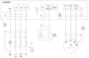
- Disconnecting device
- Two protective earth (ground) conductors. Drive safety standard IEC/EN 61800-5-1 requires two PE conductors if the cross-sectional area of the PE conductor is less than 10 mm Al. For example, you can use the cable shield in addition to the fourth conductor. Cu or 16 mm
- Use a separate grounding cable or a cable with a separate PE conductor for the line side, if the conductivity of the fourth conductor or shield does not meet the requirements for the PE conductor.
- Use a separate grounding cable for the motor side, if the conductivity of the shield is not sufficient, or if there is no symmetrically constructed PE conductor in the cable.
- 360-degree grounding of the cable shield is required for the motor cable and brake resistor cable (if used). It is also recommended for the input power cable.
- Brake resistor and resistor cable (optional).
Connection procedure (shielded cables)
For the tightening torques, refer to Terminal data for the power cables.
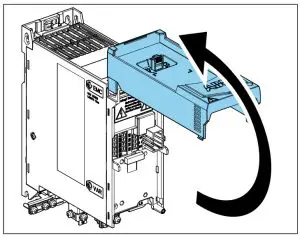
- Loosen the screw on the front cover. Then lift the front cover-up.
- Attach the residual voltage warning sticker in the local language to the drive.
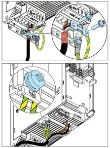
- Strip the motor cable.
- Ground the motor cable shield under the grounding clamp.
- Twist the motor cable shield into a bundle, mark it and connect it to the grounding terminal.

- Connect the phase conductors of the motor cable to terminals T1/U, T2/V and T3/W.
- If used, connect the brake resistor cable to terminals R- and UDC+. Use a shielded cable and ground the shield under the grounding clamp.
- Make sure that the R- and UDC+ terminal screws are tightened. Do this step also if you do not connect cables to the terminals.
- Strip the input power cable.
- If the input power cable has a shield, ground the shield under the grounding clamp. Then twist the shield into a bundle, mark it and connect it to the grounding terminal.

- Connect the PE conductor of the input power cable to the grounding terminal. If necessary, use a second PE conductor.
- In 3-phase drives, connect the phase conductors of the input power cable to terminals L1, L2 and L3. In 1-phase drives, connect the phase and neutral conductors to terminals L1 and L2.
- Mechanically attach the cables on the outside of the drive.
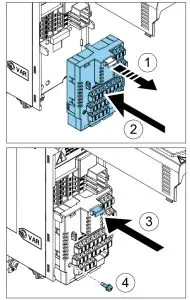
Install the communication module
To install the communication module (I/O module or Fieldbus module):
- Pull out the locking tab of the communication module.
- Align the communication module contacts with the contacts on the drive.
Carefully push the module into position. - Push in the locking tab of the communication module.
- Tighten the locking screw to fully attach and electrically ground the communication module.
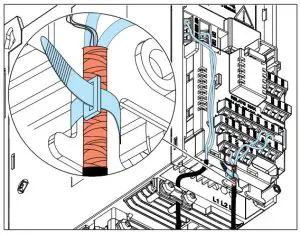
Connect the control cables
Do the connections according to the application macro that you select. The ABB standard macro is the default macro. Keep the signal wire pairs twisted as near to the terminals as possible to prevent inductive coupling. The tightening torque for the terminal connections is 0.5 … 0.6 N·m (4.4 … 5.3 lbf·in).
- Strip a part of the outer shield of the control cable for grounding.
- Use a cable tie to ground the outer shield to the grounding tab.
- Strip the control cable conductors.
- Connect the conductors to the correct control terminals.
- Connect the shields of the twisted pairs and grounding wires to the SCR terminal.
- Mechanically attach the control cables on the outside of the drive.

Default I/O connections (ABB standard macro) 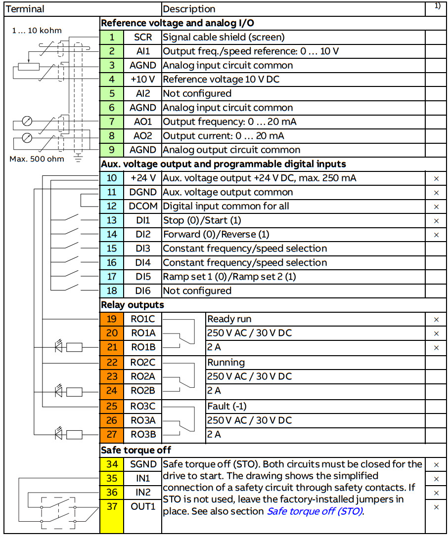 1) × = on base unit, empty = on RIIO-01 I/O extension module
Embedded Fieldbus connection
You can connect the drive to an EIA-485 serial communication link through the embedded Fieldbus interface on the RIIO-01 module. The embedded Fieldbus interface supports the Modbus RTU protocol.
To configure Modbus RTU communication with the embedded Fieldbus:
- Connect the Fieldbus cables and the necessary I/O signals.
- Use the termination switch to set the correct termination settings.
- Power up the drive and set the necessary parameters.
A connection example is shown below.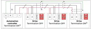
- The devices at the ends of the Fieldbus must have the termination set to ON. All other devices must have the termination set to OFF (1).
- Attach the cable shields together at each drive, but do not connect them to the drive.
Connect the shields only to the grounding terminal in the automation controller. - Connect the signal ground (DGND) conductor to the signal ground reference terminal in the automation controller. If the automation controller does not have a signal ground reference terminal, you can connect the signal ground to the cable shields through a 100-ohm resistor, preferably near the controller.
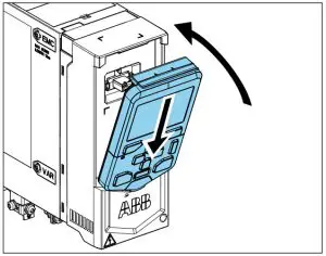
Install the control panel
To install the control panel:
- Close the front cover and tighten the screw.
- Put the bottom edge of the control panel into position.
- Push the top of the control panel until it locks into position.
Startup the drive
![]() WARNING! Before you start up the drive, make sure that the installation is completed. Make sure also that it is safe to start the motor.
WARNING! Before you start up the drive, make sure that the installation is completed. Make sure also that it is safe to start the motor.
Disconnect the motor from other machinery, if there is a risk of damage or injury.
The control panel has softkeys below the display to access the related commands, and arrow keys to navigate the menu and change parameter values.
Push the “?” button to open the help function.
Make sure that you have the motor nameplate data available.
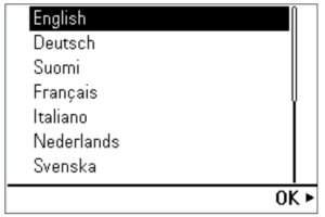
- Power up the drive. The setup assistant runs automatically. Wait until the control panel shows the language selection list.
- Select the user interface language with the arrow keys, then push the right softkey (OK).

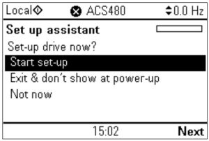
- Select Start set-up and push the right softkey (Next).

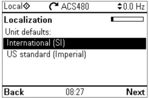
- Select the localization and push the right softkey (Next).

- To complete the setup assistant, enter the settings and values when you are prompted.
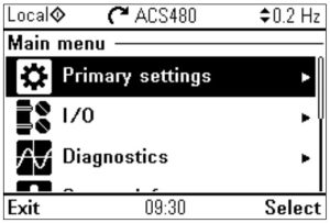
You can also use Primary settings in the Main menu to configure the unit.
In Primary settings, you can select a macro, set operation limits (speed), acceleration and deceleration ramps as required by the application.
In I/O, you can define external control signal sources (IO or Fieldbus).
![]() WARNING! If you activate the automatic fault reset or automatic restart functions of the drive control program, make sure that no dangerous situations can occur. These functions reset the drive automatically and continue operation after a fault or supply break. If these functions are activated, the installation must be clearly marked as defined in IEC/EN 61800-5-1, subclause 6.5.3, for example, “THIS MACHINE STARTS AUTOMATICALLY”.
WARNING! If you activate the automatic fault reset or automatic restart functions of the drive control program, make sure that no dangerous situations can occur. These functions reset the drive automatically and continue operation after a fault or supply break. If these functions are activated, the installation must be clearly marked as defined in IEC/EN 61800-5-1, subclause 6.5.3, for example, “THIS MACHINE STARTS AUTOMATICALLY”.
Fieldbus settings
If necessary, configure the drive for Fieldbus communication. The table below shows the minimum set of parameters required to configure Modbus RTU communication through the embedded Fieldbus interface. If you use a Fieldbus adapter, refer to the applicable Fieldbus adapter documentation.
| No. | Name | Value |
| 20. | Excel commands | Embedded Fieldbus |
| 22. | Excel speed refl (vector) | EFB refl |
| 28. | Excel frequency refl (scalar) | EFB refl |
| 31. | Fault reset selection | All 1 |
| 58. | Protocol enable | Modbus RTU |
| 58. | Node address | 1 (default) |
| 58. | Baud rate | 19.2 kbps (default) |
| 58. | Parity | 8 EVEN 1 (default) |
If you select DI1, you must connect the reset signal to digital input DI1.
Warnings and faults
| Warning | Fault | Description |
| A2A1 | 2281 | Warning: Current calibration is done at the next start. Fault: Output phase current measurement fault. |
| A2B1 | 2310 | Overcurrent. The output current is more than the internal limit. This can be caused by an earth fault or phase loss. |
| A2B3 | 2330 | Earth leakage. A load unbalances that is typically caused by an earth fault in the motor or the motor cable. |
| A284 | 2340 | Short circuit. There is a short circuit in the motor or the motor cable. |
| – | 3130 | Input phase loss. The intermediate DC circuit voltage oscillates. |
| 3181 | Cross-connection. The input and motor cable connections are incorrect. | |
| A3A1 | 3210 | DC link overvoltage. There is an overvoltage in the intermediate DC circuit. |
| A3A2 | 3220 | DC link undervoltage. There is an undervoltage in the intermediate DC circuit. |
| – | 3381 | Output phase loss. All three phases are not connected to the motor. |
| SO | 5091 | Safe torque off. The Safe torque off (STO) function is on. |
| 6681 | EFB communication loss. There is a problem with the embedded Fieldbus connection. | |
| 7510 | FBA A communication. Communication is lost between drive and Fieldbus adapter, or between controller and Fieldbus adapter. | |
| A7AB | – | Extension I/O configuration failure. The I/O module is not installed, or ABB limited macro is not selected. |
| AFF6 | – | Identification run. The motor ID run occurs at the next start. |
| – | FA81 | Safe torque off 1. The Safe torque off circuit 1 is broken. |
| – | FA82 | Safe torque off 2. The Safe torque off circuit 2 is broken. |
Ratings
| IEC type ACS480- 04-… | Input ratings | Output ratings | Frame size | |||||||
| No choke | With choke | Max. current | Nominal use | Light-duty use | Heavy-duty use | |||||
| /IN | /IN | /max | 6i | Ph | ‘Id | Ftd | 4id | Pied | ||
| AA | A | A | kW | A | kW | A | kW | |||
| 1-phase UN = 230 V¹) | ||||||||||
| 02A4-1 | 5.0 | 4. | 3. | 2. | 0.37 | 2. | 2. | 2. | 0.25 | RO |
| 03A7-1 | 7. | 6. | 4. | 4. | 0.55 | 4. | 4. | 2. | 0.37 | RO |
| 04A8-1 | 9. | 8. | 7. | 5. | 0.75 | 5. | 0.75 | 4. | 0.55 | R1 |
Related documents
| ACS480 manual list | ACS480 online videos | Ecodesign information (EU 2019/1781) |
 |  |  |
| https://search.abb.com/library/Download.aspx?DocumentID=9AKK106930A8739&Language Code=en&DocumentPartId=1&Action=Launch | https://www.youtube.com/playlist?list=PLL7dUsU7kD1qhUsTlEQtOhYYcD-24nX1u | https://ecodesign.drivesmotors.abb.com/ |
| IEC type ACS48 0- 04-… | Input ratings | Output ratings | Frame size | ||||||||||
| No choke | With choke | Max. current | Nominal use | Light-duty use | Heavy-duty use | ||||||||
| /1N | /1N | /max | ‘N | 01:11 | ‘Ld | PLd | 41 d | PH d | |||||
| A | A | A | A | kW | A | kW | A | kW | |||||
| 06A9-1 | 12.0 | 12. | 9. | 7. | 1.10 | 7. | 1.10 | 5. | 0.75 | RI | |||
| 07A8-1 | 14. | 14. | 12. | 8. | 2. | 7. | 2. | 7. | 1. | RI | |||
| 09A8-1 | 19. | 17.0 | 14.0 | 10. | 2. | 9. | 2. | 8. | 2. | R2 | |||
| 12A2-1 | 24.6 21.1 | 18. | 12. | 3.0 | 12. | 3.0 | 10. | 2. | R2 | ||||
| 3-phase UN = 230 VI) | |||||||||||||
| 02A4-2 | 4. | 2. | 32 | 2. | 0.37 | 2. | 0.37 | 2. | 0.25 | RI | |||
| 03A7-2 | 5. | 3] | 4. | 3/ | 0.55 | 32 | 0.55 | 2. | 0.37 | R1 | |||
| 04A8-2 | 6. | 5. | 6/ | 5. | 0/5 | 5. | 0.75 | 4. | 0.55 | R1 | |||
| 06A9-2 | 8. | 7. | 9. | 7. | 1. | 7. | 1. | 5. | 0.75 | RI | |||
| 07A8-2 | 10. | 8. | 12. | L8 | 2. | 8. | 2. | 7. | 1. | RI | |||
| 09A8-2 | 14. | 10. | 14.0 | 10. | 2. | 9. | 2. | 8. | 2. | R1 | |||
| 12A2-2 | 17. | 12. | 18. | 12. | 3.0 | 12. | 3.0 | 10. | 2. | R2 | |||
| 17A5-2 | 22. | 18. | 22.0 | 18. | 4.0 | 17. | 4.0 | 12. | 3.0 | R3 | |||
| 25A0-2 | 29. | 25.0 | 32. | 25.0 | 6. | 24. | 6. | 18. | 4.0 | R3 | |||
| 032A-2 | 37.0 | 32.0 | 45.0 | 32.0 | 8. | 31. | 8. | 25.0 | 6. | R4 | |||
| 048A-2 | 50.0 | 48.0 | 58. | 48.0 | 11.0 | 46. | 11.0 | 32.0 | 8. | R4 | |||
| 055A-2 | 60.0 | 55.0 | 86. | 55.0 | 15.0 | 53. | 15.0 | 48.0 | 11.0 | R4 | |||
| 3-phase UN = 400 V | |||||||||||||
| 02A7-4 | 4. | 3. | 3. | 3. | 0/5 | 3. | 0/5 | 2. | 0.55 | R1 | |||
| 03A4-4 | 5. | 3. | 4] | 3. | 1. | 3. | 1. | 3. | 0/5 | R1 | |||
| 04A1-4 | 6. | 4.0 | 6. | 4.0 | 2. | 4. | 2. | 3. | 1. | RI | |||
| 05A7-4 | 9. | 6. | 7. | 6. | 2. | 5. | 2. | 4.0 | 2. | RI | |||
| 07A3-4 | 11. | 7. | 10. | 7. | 3.0 | 7. | 3.0 | 6. | 2. | R1 | |||
| 09A5-4 | 14. | 9. | 13.0 | 9. | 4.0 | 9. | 4.0 | L2 | 3.0 | RI | |||
| 12A7-4 | 18. | 13. | 17. | 13. | 6. | 12.0 | 6. | 9. | 4.0 | R2 | |||
| 018A-4 | 25. | 17.0 | 23. | 17.0 | 8. | 16. | 8. | 13. | 6. | R3 | |||
| 026A-4 | 34. | 25.0 | 31. | 25.0 | 11.0 | 24. | 11.0 | 17.0 | 8. | R3 | |||
| 033A-4 | 43. | 32.0 | 45.0 | 32.0 | 15.0 | 31. | 15.0 | 25.0 | 11.0 | R4 | |||
| 039A-4 | 52. | 38.0 | 5L6 | 38.0 | 19. | 36.0 | 19. | 32.0 | 15.0 | R4 | |||
| 046A-4 | 56.0 | 45.0 | 68. | 45.0 | 22.0 | 43. | 22.0 | 38.0 | 19. | R4 | |||
| 050A-4 | 59. | 50.0 | 81.0 | 50.0 | 22.0 | 48.0 | 22.0 | 45.0 | 22.0 | R4 | |||
| UL (NEC) type ACS480- 04-… | Input ratings | Output ratings | Frame size | ||||||||||
| No choke | With choke | Max. current | Light-duty use | Heavy-duty use | |||||||||
| /ad | /1 Ld | max | /Ld | PLd | 4-id | PHd | |||||||
| A | A | A | A | hp | A | hp | |||||||
| 1-phase UN = 230 V .) | |||||||||||||
| 02A3-1 | 5. | 4.0 | 3. | 2. | 0.5 | 2. | 0.33 | RO | |||||
| 03A5-1 | 7. | 6. | 4. | 4. | 0.8 | 2. | 0.5 | RO | |||||
| 04A6-1 | 8. | 8.0 | 7. | 5. | 1.0 | 4. | 0.75 | R1 | |||||
| 06A6-1 | 12.0 | 11. | 9. | 7. | 2. | 5. | 1.0 | R1 | |||||
| 07A4-1 | 13.0 | 13. | 12. | 7. | 2.0 | 7. | 2. | RI | |||||
| 09A3-1 | 18.0 | 16. | 14.0 | 9. | 3.0 | 7. | 2.0 | R2 | |||||
| 11A6-1 | 21. | 20. | 18. | 12. | 3.0 | 9. | 3.0 | R2 | |||||
| 3-phase UN = 230 V | |||||||||||||
| 02A3-2 | 4. | 2. | 3. | 2. | 0.5 | 2. | 0.33 | RI | |||||
| 03A5-2 | 5. | 3. | 4. | 3. | 0.75 | 2. | 0.5 | RI | |||||
| 04A6-2 | 6. | 5. | 7. | 5. | 1.0 | 3. | 0.75 | RI | |||||
| 06A6-2 | 8. | 7. | 9. | 7. | 2. | 5. | 1.0 | R1 | |||||
| 07A5-2 | 9. | 8. | 12. | 8. | 2.0 | 7. | 2. | RI | |||||
| 11A6-2 | 13. | 12. | 18. | 12. | 3.0 | 9. | 3.0 | R2 | |||||
| 017A-2 | 21. | 17. | 22.0 | 17. | 5.0 | 12. | 3.0 | R3 | |||||
| 024A-2 | 29 / | 24. | 32. | 24. | 8. | 16] | 5.0 | R3 | |||||
| 031A-2 | 36.0 | 31. | 45.0 | 31. | 10.0 | 24. | 8. | R4 | |||||
| 046A-2 | 51. | 46. | 58. | 46. | 15.0 | 308 | 10.0 | R4 | |||||
| 053A-2 | 58. | 53. | 86. | 53. | 20.0 | 46. | 15.0 | R4 | |||||
| 3-phase UN = 480 V | |||||||||||||
| 02A1-4 | 3.0 | 2. | 3. | 2. | 1.0 | 2. | 0/5 | RI | |||||
| 03A0-4 | 4. | 3.0 | 5. | 3.0 | 2. | 2. | 1.0 | RI | |||||
| 03A5-4 | 5. | 4. | 6. | 4. | 2.0 | 3.0 | 2. | RI | |||||
| 04A8-4 | 7. | 5. | 7. | 5. | 3.0 | 4. | 2.0 | R1 | |||||
| 06A0-4 | 7. | 6.0 | 10. | 6.0 | 3.0 | 5. | 3.0 | RI | |||||
| 07A6-4 | 11. | 8. | 13.0 | 8. | 5.0 | 6.0 | 3.0 | RI | |||||
| 011A-4 | 15. | 11.0 | 17. | 11.0 | 8. | 8. | 5.0 | R2 | |||||
| 014A-4 | 20. | 14.0 | 23. | 14.0 | 10.0 | 11.0 | 8. | R3 | |||||
| 021A-4 | 29. | 21.0 | 31. | 21.0 | 15.0 | 14.0 | 10.0 | R3 | |||||
| 027A-4 | 36. | 27.0 | 45.0 | 27.0 | 20.0 | 21.0 | 15.0 | R4 | |||||
| 034A-4 | 44. | 34.0 | 58. | 34.0 | 25.0 | 27.0 | 20.0 | R4 | |||||
| 042A-4 | 49. | 42.0 | 81.0 | 42.0 | 30.0 | 40.0 | 30.0 | R4 | |||||
1) 230 V drives not available at the time of publication. For availability, contact ABB.
Fuses and typical power cable sizes
| IEC type ACS480- 04-… | UL(NEC) type ACS480- 04-… | Fuses | Cable conductor sizes (Cu) | Frame size | |||
| gG | gR | UL class T1) 2) 3) | |||||
| ABB type | Bussmann type | Bussmann/ Edison type | mme | AWG | |||
| 1-phase 1.44 = 230 V | |||||||
| 02A4-1 | 02A3-1 | OFAF000H10 | 170M2695 | JJN /TJN10 | 3×1.5 + 1.5 | 16 | RO |
| 03A7-1 | 03A5-1 | OFAF000H10 | 170M2695 | JJN/TJN10 | 3×1.5 + 1.5 | 16 | RO |
| 04A8-1 | 04A6-1 | OFAF000H16 | 170M2696 | JJN/TJN20 | 3×1.5 + 1.5 | 16 | R1 |
| 06A9-1 | 06A6-1 | OFAF000H20 | 170M2697 | JJN/TJN20 | 3×1.5 + 1.5 | 16 | R1 |
| 07A8-1 | 07A4-1 | OFAF000H25 | 170M2698 | JJN/IJN25 | 3×1.5 + 1.5 | 16 | R1 |
| 09A8-1 | 09A3-1 | OFAF 000 H32 | 170M2698 | JJN /TJ N25 | 3 x2.5 + 2.5 | 14 | R2 |
| 12A2-1 | 11A6-1 | OFAF000H35 | 170M2698 | JJN/TJ N35 | 3×2.5 + 2.5 | 14 | R2 |
| 3-phase UN = 230 V | |||||||
| 02A4-2 | 02A3-2 | OFAF000H6 | 170M2694 | JJS/TJS6 | 3×1.5 + 1.5 | 16 | R1 |
| 03A7-2 | 03A5-2 | OFAF000H10 | 170M2695 | JJS/TJS10 | 3×1.5 + 1.5 | 16 | R1 |
| 04A8-2 | 04A6-2 | OFAF000H10 | 170M2695 | JJS/TJS10 | 3×1.5 + 1.5 | 16 | R1 |
| 06A9-2 | 06A6-2 | OFAF000H16 | 170M2696 | JJS/TJS20 | 3×1.5 + 1.5 | 16 | R1 |
| 07A8-2 | 07A5-2 | OFAF000H16 | 170M2696 | JJS/TJS20 | 3×1.5 + 1.5 | 16 | R1 |
| 09A8-2 | – | OFAF000H16 | 170 M2696 | JJS/TJS20 | 3×2.5 + 2.5 | 14 | R1 |
| 12A2-2 | 11A6-2 | OFAF000 H25 | 170M2697 | JJS/TJS25 | 3×2.5 + 2.5 | 14 | R2 |
| 17A5-2 | 017A-2 | OFAF000 H32 | 170M2698 | JJS/TJS35 | 3×6 + 6 | 10 | R3 |
| 25A0-2 | 024A-2 | OFAF000HSO | 170 M2699 | JJS/TJS50 | 3×6 + 6 | 10 | R3 |
| 032A-2 | 031A-2 | OFAF000H63 | 170M2700 | JJS/TJS60 | 3×10 + 10 | 8 | R3 |
| 048A-2 | 046A-2 | OFAF000H100 | 170 M2702 | JJS/TJS100 | 3×25 + 16 | 4 | R4 |
| 055A-2 | 053A-2 | OFAF000H100 | 170M2702 | JJS/TJS100 | 3×25 + 16 | 4 | R4 |
| 3-phase UN = 400 V or 480 V | |||||||
| 02A7-4 | 02A1-4 | OFAF000H6 | 170M2694 | JJS/TJS6 | 3×1.5 + 1.5 | 16 | R1 |
| 03A4-4 | 03A0-4 | OFAF000H6 | 170M2694 | JJS/TJS6 | 3×1.5 + 1.5 | 16 | R1 |
| 04A1-4 | 03A5-4 | OFAF000H10 | 170M2695 | JJS/TJS10 | 3×1.5 + 1.5 | 16 | R1 |
| 05A7-4 | 04A8-4 | OFAF000H10 | 170M2695 | JJS/TJS10 | 3×1.5 + 1.5 | 16 | R1 |
| 07A3-4 | 06A0-4 | OFAF000H16 | 170M2696 | JJS/TJS20 | 3×1.5 + 1.5 | 16 | R1 |
| 09A5-4 | 07A6-4 | OFAF000H16 | 170M2696 | JJS/TJS20 | 3×2.5 + 2.5 | 14 | R1 |
| 12A7-4 | 011A-4 | OFAF000 H25 | 170M2697 | JJS/TJS25 | 3×2.5 + 2.5 | 14 | R2 |
| 018A-4 | 014A-4 | OFAF000 H32 | 170M2698 | JJS/TJS35 | 3×6 + 6 | 10 | R3 |
| 026A-4 | 021A-4 | OFAF000HSO | 170M2699 | JJS/TJS40 | 3×6 + 6 | 10 | R3 |
| 033A-4 | 027A-4 | OFAF000H63 | 170M2700 | JJS/TJS60 | 3×10 + 10 | 8 | R4 |
| 039A-4 | 034A-4 | OFAF000H80 | 170M2701 | JJS/TJS80 | 3×16 + 16 | 6 | R4 |
| 046A-4 | – | OFAF000H100 | 170M2702 | JJS/TJS100 | 3×25 + 16 | 4 | R4 |
| 050A-4 | 042A-4 | OFAF000H100 | 170M2702 | JJS/TJS100 | 3×25 + 16 | 4 | R4 |
- The recommended branch protection fuses must be used to maintain the IEC/EN/UL 61800-5-1 listing.
- The drive is suitable for use on a circuit capable of delivering not more than 100000 symmetrical amperes (RMS) at 480 V (480 V drive types) or 240 V (240 V drive types) maximum when protected by the fuses given in this table.
- As an alternative to Class T fuses, you can use Class J or Class CF fuses of the same voltage and current rating for branch circuit protection of 3-phase drives.
Terminal data for the power cables
| Frame size | Li, L2, L3, Ti/U, T2/V, T3/W, R-, R+/UDC+, UDC- | PE | ||||||||
| Min. wire size (solid/ stranded) | Max. wire size (solid/ stranded) | Tightening torque | Max. wire size (solid/ stranded) | Tightening torque | ||||||
| mm2 | AWG | mm2 | AWG | N•m | lbf•in | mm2 | AWG | N•m | lbf•in | |
| RO | 0.5/0.5 | 18 | 4/2.5 | 10 | 0.506 | 5 | 6/4 | 10 | 1. | 11 |
| R1 | 0.5/0.5 | 18 | 4/2.5 | 10 | 0.5…0.6 | 5 | 6/4 | 10 | 1. | 11 |
| R2 | 0.5/0.5 | 18 | 4/2.5 | 10 | 0.5…0.6 | 5 | 6/4 | 10 | 1. | 11 |
| R3 | 0.5/0.5 | 18 | 10/6 | 6 | 1.2…1.5 | 11…13 | 6/4 | 10 | 1. | 11 |
| R4 | 0.5/0.5 | 18 | 25/16 | 2 | 2.5…3.7 | 22…32 | 25/16 | 4 | 3. | 26 |
Note:
- The minimum specified wire size does not necessarily have sufficient current-carrying capacity at maximum load.
- The terminals do not accept a conductor that is one size larger than the maximum specified wire size.
- The maximum number of conductors per terminal is 1.
Ambient conditions
| Requirement | During operation (installed for stationary use) |
| Installation altitude | 230 V drives: 0 … 2000 m (0 … 6562 ft) above sea level. 400/480 V drives: 0 … 4000 m (0 … 13123 ft) above sea level. At altitudes above 2000 m (6562 ft): • only TN-S and TT grounding systems are permitted • the maximum permitted voltage for the integrated relay outputs decreases. At 4000 m (13123 ft), it is 30 V. Derating: The output current must be derated 1% for each 100 m (328 ft) above 1000 m (3281 ft). |
| Surrounding air temperature | Frame RO: -10 … +50 °C (14 … 122 °F). No frost permitted. Frames R1…R4: -10 … +60 °C (14 … 140 °F). No frost permitted. The output current must be derated at temperatures above +50 °C (122 °F) as follows: • IEC types 055A-2, 039A-4, 050A-4 and UL (NEC) types 053A-2, 034A-4 and 042A-4: 2% for each added 1 °C (1.8°F) • Other types:1% for each added 1 °C (1.8°F). |
| Relative humidity | 5 … 95%. No condensation is permitted. The maximum permitted relative humidity is 60% in the presence of corrosive gases. |
| Contamination levels | No conductive dust permitted |
| Shock or free fall | Not permitted |
Dimensions and weights
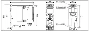
| Frame size | Dimensions | Weights | ||||||||||||||
| HI | H2 | H3 | W | D | MI | M2 | ||||||||||
| mm | in | mm | in | mm | in | mm | in | mm | in | mm | in | mm | in | kg | lb | |
| RO | 205 | 8. | 223 | 9. | 170 | 7. | 73 | 3. | 208 | 8. | 50 | 2.0 | 191 | 8. | 1.70 | 4. |
| R1 | 205 | 8. | 223 | 9. | 170 | 7. | 73 | 3. | 208 | 8. | 50 | 2.0 | 191 | 8. | 2. | 3.90 |
| R2 | 205 | 8. | 223 | 9. | 170 | 7. | 97 | 4. | 208 | 8. | 75 | 3.0 | 191 | 8. | 2. | 5. |
| R3 | 205 | 8. | 220 | 9. | 170 | 7. | 172 | 7. | 208 | 8. | 148 | 6. | 191 | 8. | 4. | 8. |
| R4 | 205 | 8. | 240 | 10. | 170 | 7. | 262 | 10. | 213 | 8. | 234 | 9. | 191 | 8. | 6. | 13. |
Free space requirements
| Frame size | Above | Below | Sides | |||
| mm | in | mm | in | mm | in | |
| R0…R4 | 75 | 3 | 75 | 3 | 0 | 0 |
- A side-mounted option requires approximately 20 mm (0.8 in) of space on the right side of the drive.
Markings
The applicable markings are shown on the type designation label of the drive.
Safe torque off (STO)
The drive has a Safe torque off function (STO) in accordance with IEC/EN 61800-5-2. It can be used, for example, as the final actuator device of safety circuits that stop the drive in case of danger (such as an emergency stop circuit).
When activated, the STO function disables the control voltage of the power semiconductors of the drive output stage, thus preventing the drive from generating the torque required to rotate the motor. The control program generates an indication as defined by parameter 31.22. If the motor is running when Safe torque off is activated, it coasts to a stop. Closing the activation switch deactivates the STO. Any faults generated must be reset before restarting.
The STO function has a redundant architecture, that is, both channels must be used in the safety function implementation. The safety data given is calculated for redundant use and does not apply if both channels are not used.
 WARNING! The STO function does not disconnect the voltage from the main and auxiliary circuits of the drive.
Notes:
- If stopping by coasting is not acceptable, stop the drive and machinery using the appropriate stop mode before activating the STO.
- The STO function overrides all other functions of the drive.
Wiring
The safety contacts must open/close within 200 ms of each other.
A double-shielded twisted-pair cable is recommended for the connection. The maximum length of the cabling between the switch and the drive control unit is 300 m (1000 ft). Ground the shield of the cable at the control unit only.
Validation
To ensure the safe operation of a safety function, a validation test is required.
The test must be carried out by a competent person with adequate expertise and knowledge of the safety function. The test procedures and report must be documented and signed by this person. Validation instructions of the STO function can be found in the drive hardware manual.
Technical data
- Minimum voltage at IN1 and IN2 to be interpreted as “1”: 13 V DC
- STO reaction time (shortest detectable break): 1 ms
- STO response time: 2 ms (typical), 5 ms (maximum)
- Fault detection time: Channels in different states for longer than 200 ms
- Fault reaction time: Fault detection time + 10 ms
- STO fault indication (parameter 31.22) delay: < 500 ms
- STO warning indication (parameter 31.22) delay: < 1000 ms
- Safety integrity level (EN 62061): SIL 3
- Performance level (EN ISO 13849-1): PL e
The drive STO is a type A safety component as defined in IEC 61508-2.
For the full safety data, exact failure rates and failure modes of the STO function, refer to the drive hardware manual.
Declarations of conformity
3AXD50000047400 Rev D EN 2021-07-20
Original instructions.
© Copyright 2021 ABB. All rights reserved.