![]() STT 3000 Temperature Transmitter
STT 3000 Temperature Transmitter
Instructions Manual
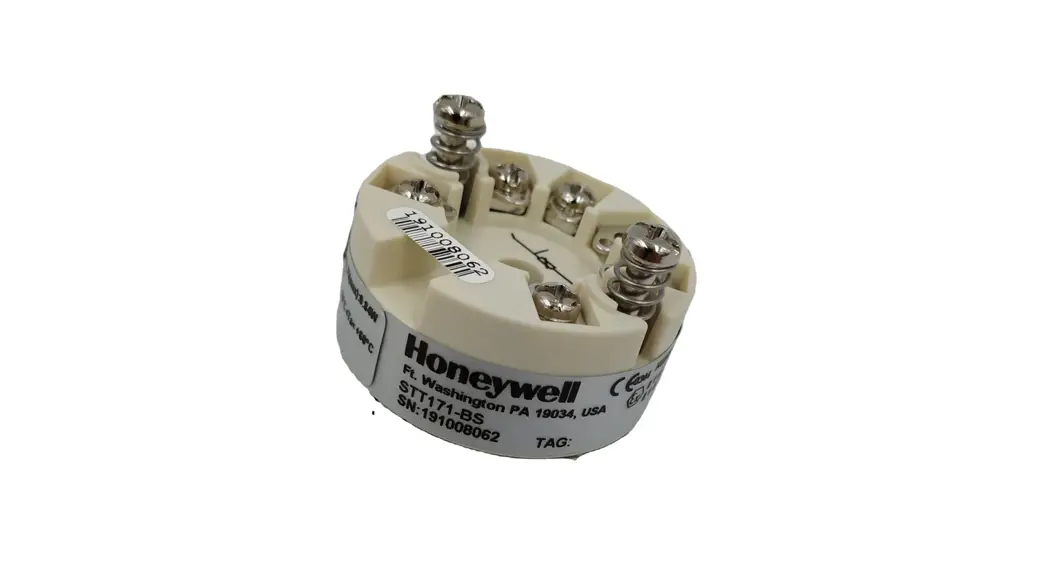
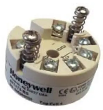
STT 3000 Temperature Transmitter Series STT170
Model Selection Guide
34-44-16-07 Issue 33
Instructions
- Choose the Availability column based on the Key Number.
- A dot (• ) denotes unrestricted availability.
- Select the desired Key Number based on the desired communications protocol.
- Select options and approvals from Tables.

Model Selection Guide
With Price Data
Honeywell Proprietary
Key Number
| Description | Selection | Availability | |||
| 4-20mA Output, RTD input | STT171 | ↓ | ↓ | ↓ | ↓ |
| 4-20mA Output, universal input | STT173 | ||||
| HART Protocol, 4-20mA output | STT17H | ||||
| Configuration tool for STT171, 173 and 17H | STT17C | ||||
Table I – Safety Approvals
| Approval Body | Approval Type | Location or Classification | |||||
| None | No approval body certifications included | 00 | □ | □ | □ | □ | |
|
FM, CSA, ATEX | Intrinsically Safe
Non-Incendive | Class I, Div. 1, Groups A, B, C, D, T4 Class I, Zone 0/1; AEx ia IIC, T4 Class I, Div. 2, Groups A, B, C, D, T4 |
BS |
□ |
□ |
□ | |
| Intrinsically Safe
Non-Incendive | Class I, Div. 2, Groups A, B, C, D, T4 Class I, Zone 0/1; Ex ia IIC, T4 Class I, Div. 2, Groups A,B, C,D, T4 | ||||||
| * Intrinsically Safe Zone 0/1 | Ex II 1 GD, EEx ia IIC, T4..T6 Ex II 2 (1) GD, T4..T6 | ||||||
| Non-Incendive Zone 2 | Class I, Div. 2, Groups A, B, C, D, T4 Ex II 3 G, EEx nA [L] T4..T6 | BN | □ | ||||
When installed in Field Mount Enclosure Table IV, E _ _, or T _ _
| FM Approval | Intrinsically Safe
Non-Incendive | Class I, Div. 1, Groups A,B, C,D, T4 Class I, Zone 0/1; AEx ia IIC, T4 Class I, Div. 2, Groups A, B,C, D, T4 | 1G | e | e | e | |
| CSA | Intrinsically Safe
Non-Incendive | Class I, Div. 2, Groups A,B, C,D, T4 Class I, Zone 0/1; Ex ia IIC, T4 Class I, Div. 2, Groups A,B,C,D, T4 | 2G | e | e | e | |
| ATEX | * Intrinsically Safe Zone 0/1 | Ex II 1 GD, EEx ia IIC, T4..T6 Ex II 2 (1) GD, T4..T6 | 3S | e | e | e |
* Ex II GD or II 2 (1) GD allows for installation in potentially explosive atmospheres caused by the presence of combustible dust only when mounted in a metal enclosure of form B according to DIN 43729 (Head-Mount enclosure) that provides a degree of protection of at least IP 6X in accordance with EN 60529, that is suitable for the application and is correctly installed.
TABLE II – No Option
| No Option | 0 | □ | □ | □ | □ |
TABLE III – Configuration & Certificates
| Configuration | None – Factory Default Configuration Supplied Custom Transmitter Configuration with Printed Report ** | 0 _ _ T _ _ | □ □ | □ □ | □ □ | □ |
| Calibration | Custom Transmitter Calibration with Printed Report ** | C _ _ | □ | □ | □ | |
| Optional Certificates | No Option | _ 0 _ | □ | □ | □ | □ |
| No Certificate of Conformance/Origin Certificate of Conformance/Origin | _ _ 0 _ _ R | □ □ | □ □ | □ □ |
The minimum value of orders acceptable for Honeywell is USD 500. A handling fee is the amount of the difference between USD
| TABLE IV – Transmitter Housing and Integral Meters (Reference EN0I-6032 for details) | 1 | 3 ↓ | H ↓ | C ↓ | |||
| Housing | No Housing Supplied | 0 _ _ | • | • | • | • | |
| Field Housing | Aluminum with Beige Epoxy Coating 316 Stainless Steel | E _ _ T _ _ | d d | d d | d d | ||
| Head Mt | Type 4X housing – Beige | C _ _ | g | g | g | ||
| Cable/ Conduit Entry | Not Applicable – No Housing Supplied 1/2″ NPT Cable/ Conduit Entry M20 x 1.5 Cable/ Conduit Entry | _ 0 _ _ N _ _ M _ | • • • | • • • | • • • | • | |
| Integral Meter | No Integral Meter Supplied E.U. Meter for Field Mount Housing | _ _ 0 _ _ E | • h | • h | • h | • | |
TABLE V – Optional Equipment
|
Mounting | No mounting bracket Carbon steel pipe mounting bracket for 2″ pipe Stainless Steel mounting bracket for 2″ pipe Spring loading mounting set DIN rail mounting clip (top hat or G rail) | 0_ _ M_ _ S_ _ L_ _ D_ _ | □ e | □ e | □ e | □ |
|
M20 adaptors | No adaptors required 1 adaptor for M20 x 1.5 wiring entry 2 adaptors for M20 x 1.5 wiring entry | _ 0 _ _ 1 _ _ 2 _ | □ □ □ | □ □ □ | □ □ □ | □ |
| 3/4″NPT adaptors | 1 adaptor for 3/4″NPT wiring entry | _ 3 _ | □ | □ | □ | |
| Lightning Protection | No lightning protection supplied Externally Mountable to Field Mount Housing Internal lightning protection | _ _ 0 _ _ L _ _ S | □ □ □ | □ □ □ | □ □ □ | □ |
RESTRICTIONS
| Restriction Letters | Available Only With | Not Available With | ||
| Table | Selection | Table | Selection | |
| b | VI | Select only one option from this group | ||
| d | IV | _N _ | ||
| e | IV | E _ _, or T _ _ | ||
| f | IV | 0_ _ | ||
| g | IV | _0E | ||
| h | I | 00 | ||
| IV | E _ _, or T _ _ | |||
ACCESSORIES Part Number
| DIN rail clip | 50017850-001 |
** If the Custom Configuration option “T” or the Custom Calibration option “C” is ordered, the configuration or calibration information required must me be entered as a note on the order. Any of the following elements can be included, based on the selected model number:
(STT171, STT173, STT17H) Tag Number, CJC, Sensor Type, Sensor Wiring, Temperature Units, URV/LRV, Output Range, Output Limits, Sensor Error Action, Response Time.
(STT17F) Tag Number, Sensor Type, URV/LRV,
Burnout- High or Low, Response Time
*** Refer to Part Price List (PPL) or Web Channel for pricing.
The minimum value of orders acceptable for Honeywell is USD 500. A handling fee is the amount of the difference between USD 500 and the actual purchase price.
![]()


