![]() C7031G; C7041B,C,F,K; T775-SENS-OAT/STRAP Series 2000 Electronic Temperature Sensors
C7031G; C7041B,C,F,K; T775-SENS-OAT/STRAP Series 2000 Electronic Temperature Sensors
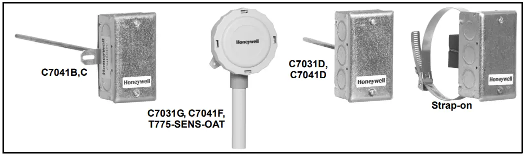
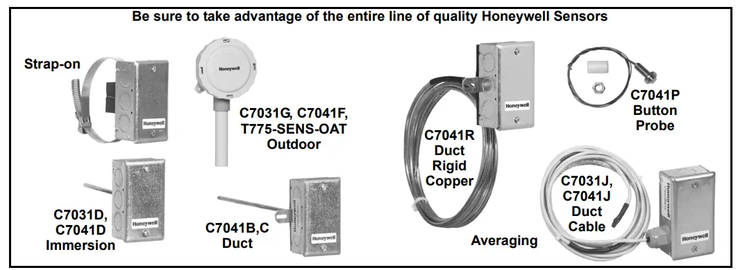
C7031G, C7041F, T775-SENS-OAT OUTDOOR; STRAP-ON, C7041B,
C DUCT; C7031D, C7041D IMMERSION
INSTALLATION INSTRUCTIONS
SENSOR APPLICATIONS
Table 1. Electronic Sensor Application Guide
| Model | Application | Output | Element Insertion Length |
| C7031D | Immersion | 1097 ohms @ 77 F | 5 in. (127 mm) |
| C7031 G | Outdoor | 3484 ohms @ 77 F | — |
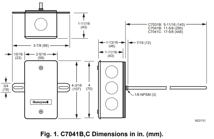
| C7041B | Duct | 20 K ohm NTC @ 77 F | 6 in. (152) or 12 in. (305 mm) |
| C7041C | Duct | 20 K ohm NTC @ 77 F | 18 in. (457 mm) |
| C7041D | Immersion | 20 K ohm NTC @ 77 F | 5 in. (127 mm) |
| C7041 F | Outdoor | 20 K ohm NTC @ 77 F | — |
| C7041K | Strap-On | 20 K ohm NTC @ 77 F | — |
| T775-SENS-OAT | Outdoor | 1097 ohms @ 77 F | — |
| T775-SENS-STRAP | Strap-On | 1097 ohms @ 77 F | — |
C7031G; C7041B,C,F,K; T775-SENS-OAT/STRAP SERIES 2000 ELECTRONIC TEMPERATURE SENSORS
INSTALLATION
When Installing this Product…
- Read these instructions carefully. Failure to follow them could damage the product or cause a hazardous condition.
- Check the ratings given in the instructions and on the product to make sure the product is suitable fo your application.
- Installer must be a trained, experienced service technician.
Mounting
The mounting method depends on the particular sensorapplication. The following procedures include:
— duct applications
— outdoor applications
— immersion well applications
— strap-on applications
NOTE: Also refer to the instructions for the electronic control.
Duct Mounting (C7041B,C)
IMPORTANT
Select a spot for the sensor that will exposed it to average duct air temperature. Avoid locations where stratification can cause sensing errors.
- Cut a hole in the duct just large enough to accept the sensing element.
- Use the sensor’s case to mark locations of pilot holes for the mounting screws.
- Drill pilot holes and fasten the sensor to the duct.
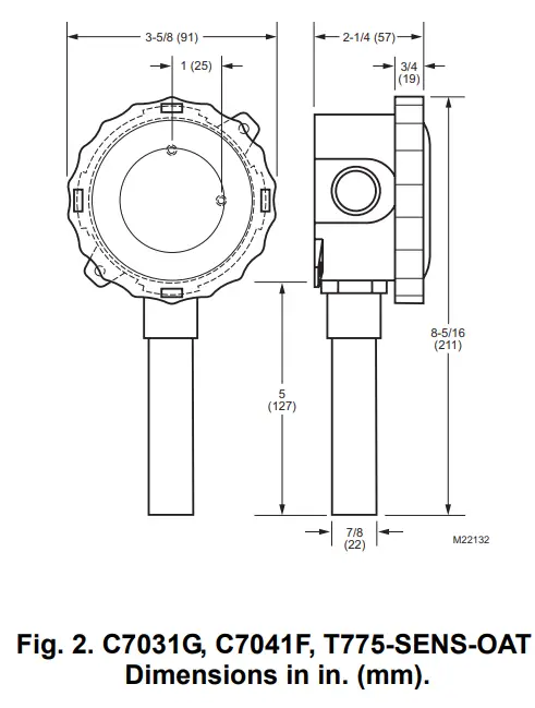
Outdoor Mounting (C7031G, C7041F;
T775-SENS-OAT)
The outdoor air temperature sensors have a weatherproof enclosure. Mount the sensor where it can sense average outdoor air temperature. Allmounting hardware is provided with the sensor. Be sure to mount the sensor out of direct sunlight with the sensor probe point down. Normally, the north side of a building provides a suitable location.
NOTE: C7031G, C7041F, and T775-SENS-OAT are weatherproof for outdoor use. Knockouts allow for 1/2 in. conduit connection.
- Remove and set aside the wiring box cover.
- Mount the sensor to standard 1/2 in. conduit.
NOTE: Mount sensor so that the element points down. - Make wiring connections using two wire nuts.
- Reattach the wiring box cover.
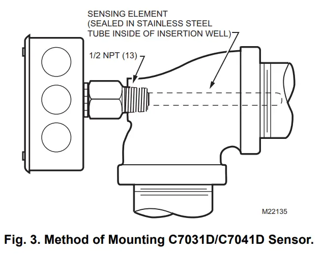
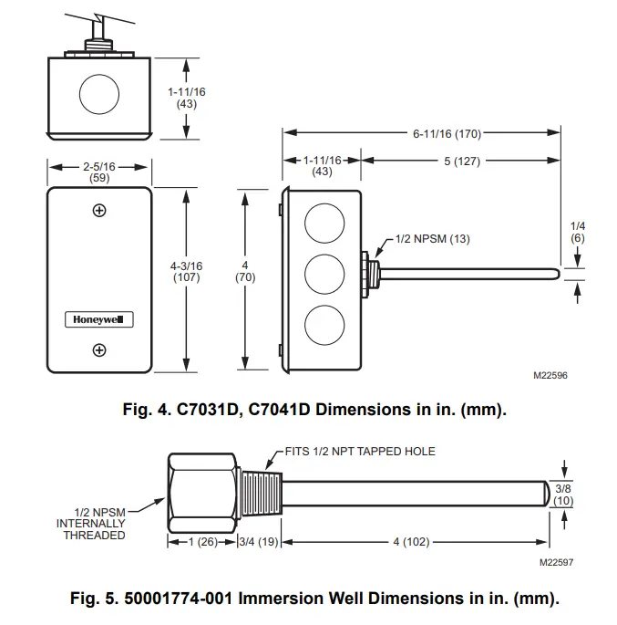
Immersion Well Mounting (C7031D, C7041D)
NOTE: The C7041D uses the 50001774-001 Well Assembly. See Fig. 5 for dimensions.
The C7031D Sensor includes an immersion well. The C7041D Sensor does not include a well. For the C7041D,order the well as an accessory (part no.: 50001774-001).
When used on a boiler, follow the manufacturer instructions for location. If a tapped hole is not provided for the immersion well, provide one as follows:
- Drain boiler and drill a 23/32 in. (18 mm) hole at the selected location.
- Cut threads in the hole with a 1/2 in. (13 mm) by 14 NPT tap.
In other installations, mount the immersion well in an elbow with a heel outlet as shown in Fig. 3.
- Drain the system, if you have not already done it, and open the tapped hole.
- Put pipe joint compound on the threads of the immersion well and screw it into the tapped hole or elbow, tightening it securely.
- Refill the system and check for leaks.
Mount the C7031D/C7041D into the well:
NOTE: Mounting using previously installed Honeywell wells (part no.: 32005960-001) requires an adapter (part no.: 50001775-001).
- When an adapter is required, first thread it into the well no more than one or two turns.
- Slide the sensor into the well.
- Rotate the sensor to thread it tightly into the adapter and the adapter tightly into the well.
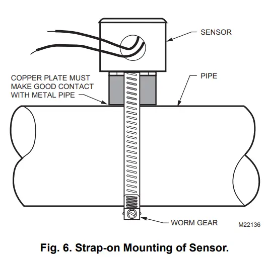
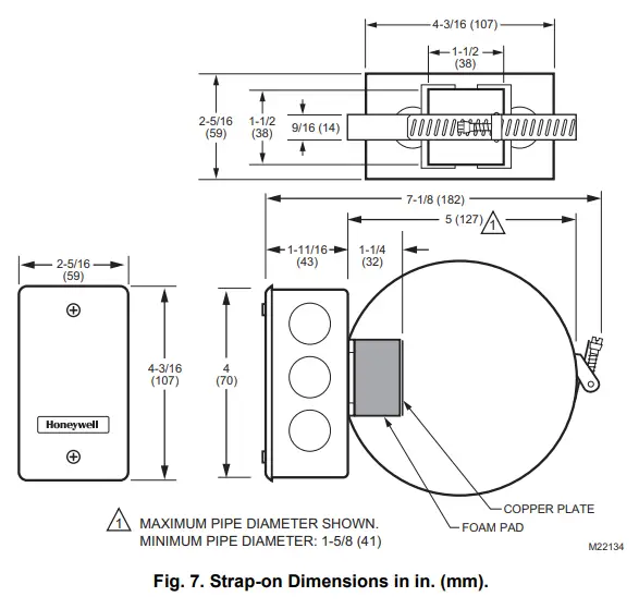
Strap-on Mounting (C7041K, T775-SENSSTRAP)
The Sensor mounts on metal pipes from 1-5/8 inch to fiveinches in diameter using the straps supplied. Clean the pipe surface where the sensor makes contact before mounting. If necessary, remove pipe insulation at the installation point. Thermal compound is recommended. Locate the sensor on the discharge pipe within 3 ft. (0.9 m) of the boiler. See Fig. 6.
NOTE: Insulation around the contact area increases sensor accuracy.
![]() Automation and Control Solutions
Automation and Control Solutions
Honeywell International Inc.
1985 Douglas Drive North
Golden Valley, MN 55422
customer.honeywell.com
® U.S. Registered Trademark
© 2008 Honeywell International Inc.
62-0220—03 J.I. Rev. 01-08
Honeywell Limited-Honeywell Limitée
35 Dynamic Drive
Toronto, Ontario M1V 4Z9![]() Printed in U.S.A. on recycled
Printed in U.S.A. on recycled
paper containing at least 10%
post-consumer paper fibers.