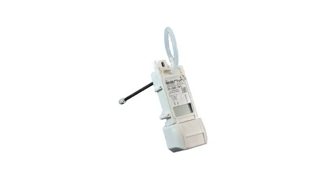
![]() P5 Universal Pressure Sensor
P5 Universal Pressure Sensor
Instruction Manual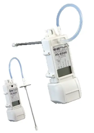
P5 Universal Pressure Sensor
Versatile pobe: remote or duct mount
- RP-6 Remote/duct probe, 6”
- Accepts both 1/8” and 1/4” tubing
PRODUCT APPLICATION LIMITATION:
Senva products are not designed to be used as the lone device for life or safety applications. Senva products are not intended for use in critical applications such as nuclear facilities, human implantable device or life support. Senva believes a systems approach to safety is necessary for these types of applications. Senva is not liable, in whole or in part, for any claims or damages arising from such uses.
DIMENSIONS
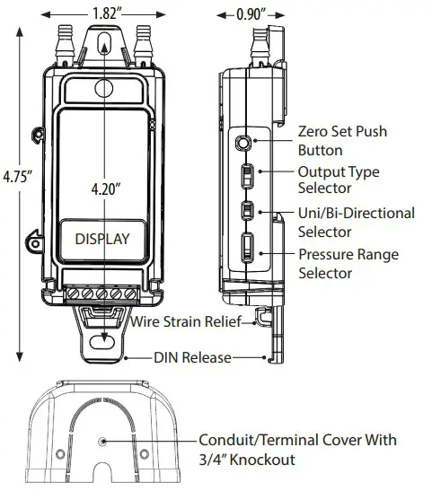
INSTALLATION
- Screw mount sensor directly to duct, or in panel using selftapping screws or attach to a DIN rail (2 possible orientations for DIN mounting, BACK and LEFT SIDE).
- Move slide switch to select appropriate analog output (420mA 2 -Wire or 3-Wire configurations or 5V/10V
- Move slide switch to select desired pressure range and operation mode (Uni or Bi-Directional)
- Plumb air lines to sensor hose barbs(Accepts 1/8” & 1/4” ID tubing). High (+) and low (-) ports are labeled on the sensor.
- Wire sensor for voltage or current output as shown in the wiring diagrams.
- Recommendation: Apply power to sensor. With no pressure applied, press the ZERO SET button for 2 seconds. (For best results, temporarily connect high and low pressure ports.)
LED STATUS/INDICATION
LED indicator will flash every 5 seconds for normal operation.
LED indicator will rapidly flash when applied pressure greater than 110% of selected range.
LED indicator will rapidly flash momentarily when zeroing process is complete.
IMPORTANT!
IMPORTANT WARNINGS
- Only qualified trade installers should install this product
- This product is not intended for life-safety applications
- Do not install in hazardous or classified locations
- The installer is responsible for all applicable codes
- De-energize power supply prior to installation or service
- Forming a “drip-loop” (allowing tubing to dip below the level of the sensor hose barbs) is recommended to protect the sensor from damage caused by condensation.
TROUBLESHOOTING
| Symptom | Solution |
| No output | Check wiring. Ensure power supply meets requirements. |
| Pressure reading error | Verify control panel software is configured for correct output scaling. |
| Verify switch settings. | |
| Verify tubing is not pinched or leaking. | |
| Possible contamination. Ensure sensor is used only on dry air or nitrogen. |
SPECIFICATIONS
| Power Supply | 12-30VDC/24VAC(1), 30mA max | |
| Output type | Selectable outputs | 4-20mA loop powered, 4-20 mA 3-wire, 0-5VDC, 0-10VDC |
| Output scaling | P5-0100 | 0-1” (Selectable 0.1, 0.25, 0.5, 1.0, ±0.1, ±0.25, ±0.5, ±1.0” WC) |
| P5-0500 | 0-5” (Selectable 0.1, 0.25, 2.5, 5.0, ±0.1, ±0.25, ±2.5, ±5.0” WC) | |
| P5-0501 | 0-5” (Selectable 0.5, 1.0, 2.5, 5.0, ±0.5, ±1.0, ±2.5, ±5.0” WC) | |
| P5-1000 | 0-10” (selectable 1.0, 2.5 ,5.0, 10, ±1.0, ±2.5 ,±5.0, ±10”WC) | |
| P5-2500 | 0-25” (selectable 5.0, 10, 15, 25, ±5.0, ±10, ±15, ±25” WC) | |
| P5-1250Pa | 0-1250 Pa (selectable 25, 50, 625, 1250, ±25, ±50, ±625, ±1250 Pa) | |
| P5-2500Pa | 0-2500 Pa (selectable 250, 625, 1250, 2500, ±250, ±625, ±1250, ±2500 Pa) | |
| P5-6250Pa | 0-6250 Pa (selectable 1250, 2500, 3750, 6250, ±1250, ±2500, ±3750, ±6250 Pa) | |
| Operating Temperature | Operating range | -4 to 140F (-20 to 60ºC) |
| Media compatibility | Compensated range | -4 to 140F (-20 to 60ºC) |
| Sensor Type | Dry, oil-free air, N2 | |
| MEMS silicon piezoresistive; precision calibrated | ||
| Sensor Performance | Accuracy | ±1.0% of selected range (combined linearity and hysteresis) |
| Zero Tolerance | Included in accuracy specification | |
| Span Tolerance | ±1.00% | |
| Zero Drift (1 year) | 0.004”WC/year max. 0.4% for units >0.5”w.c. | |
| Thermal Shift (Zero and Span) | 0.02% FSO/ºC (0.01%FSO/ºF) measured from 22ºC (72ºF) | |
| Overpressure | up to 5” models: 41.5”w.c.; 10” models: 133”w.c.; 25” models: 332”w.c. | |
| Max Static Line Pressure | up to 5” models: 41.5”w.c.; 10” models: 133”w.c.; 25” models: 332”w.c. | |
| Burst Pressure | up to 5” models: 83”w.c.; 10” models: 166”w.c.; 25” models: 415”w.c. | |
| Position Sensitivity | Non-position sensitive | |
| Auto-zero input | Push-button and N.O. contact closure | |
| Agency | Compliance | CE, RoHS |
| Enclosure | Material | UL94 5VB, ABS |
| Environmental | NEMA 1 |
- One side of transformer secondary is connected to signal common. Dedicated transformer is recommended. For 2-wire, use DC only.
TYPICAL APPLICATIONS
Velocity: Use a pitot tube and plumb high (+) port to total pressure (Pt) connection and low (-) port to static pressure (Ps) connection to directly read Pt-Ps = Pv. Apply correction constant provided by pitot tube manufacturer.
Duct Static: Install a static pressure pickup tube approximately 2/3 of the way down the discharge air duct and plumb to high (+) port for positively pressurized ducts. 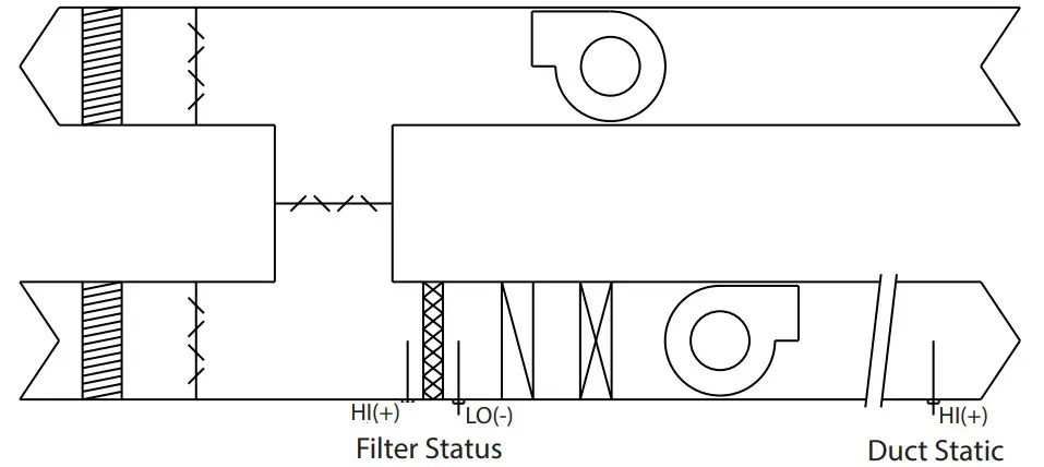 WIRING DIAGRAMS
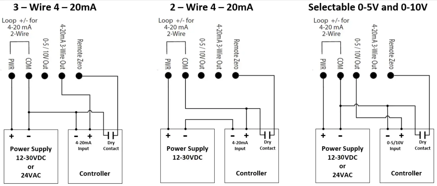
![]() senvainc.com 1-866-660-8864
senvainc.com 1-866-660-8864
(F)1-503-296-2529 9290
SW Nimbus Ave. Beaverton Oregon 97008


