SENVA P6 Pro Series Pressure
Product Information
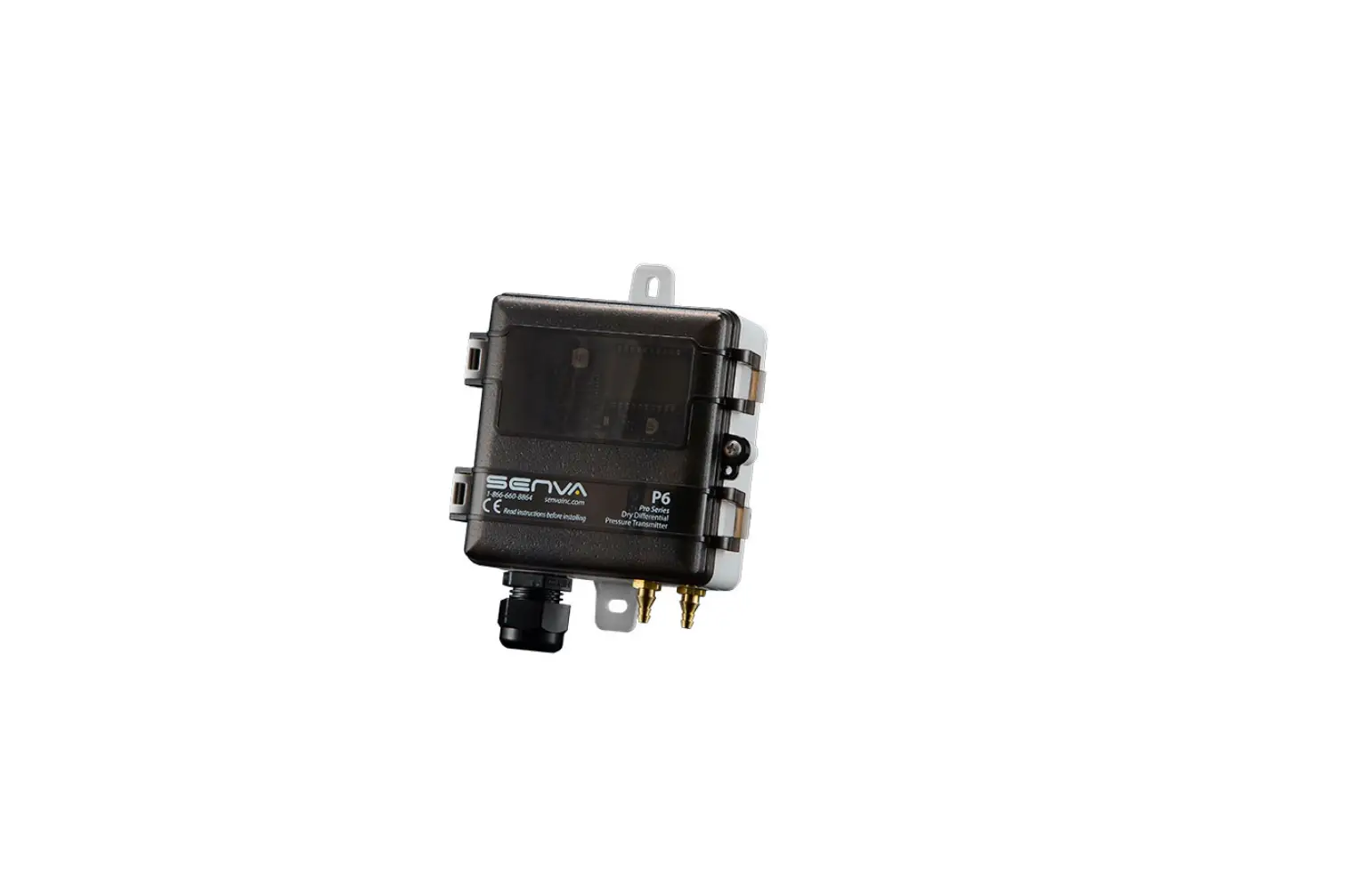
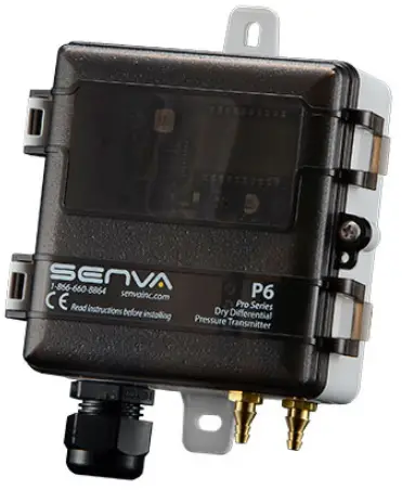
P6 Universal Pressure Sensor
The P6 Universal Pressure Sensor is a device that helps measure pressure levels in air or nitrogen. It comes in three models (0-5/15/40 W.C.) with four selectable ranges. The device has a screw mount and can be directly mounted on a duct or panel using self-tapping screws. The output selection switch allows for choosing the appropriate analog output (4-20mA 2-Wire or 3-Wire configurations or 5V/10V). The rotary range selection dial helps to select the desired pressure range position. The device also comes with configuration switches to adjust the device settings. The sensor hose barbs accept 1/8 & 1/4 ID tubing and have high (+) and low (-) ports labeled on the sensor. The device can be wired for voltage or current output as shown in the wiring diagrams.
It is important to note that Senva products are not designed to be used as the lone device for life or safety applications. Senva products are not intended for use in critical applications such as nuclear facilities, human implantable device or life support.
Product Usage Instructions
- Mount the sensor directly to the duct or panel using self-tapping screws.
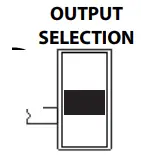
- Move the output selection switch to select the appropriate analog output.
- Move the rotary range selection dial to the desired pressure range position.
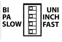
- Use the configuration switches to adjust the device settings.
- Plumb air lines to sensor hose barbs (accepts 1/8 & 1/4 ID tubing). High (+) and low (-) ports are labeled on the sensor.
- Wire the sensor for voltage or current output as shown in the wiring diagrams.
- Apply power to the sensor. With no pressure applied, press the ZERO SET button for 2 seconds. (For best results, temporarily connect high and low pressure ports together while zeroing.)
- For duct installation, screw the duct probe into the back of the enclosure and connect tubing from high (+) pressure port to duct probe. Drill a 1/4 hole in duct. Install sensor using gasket and screws provided.
It is important to note that the LED indicator will flash every 5 seconds for normal operation. The LED indicator will rapidly flash when applied pressure is greater than 110% of the selected range. The LED indicator will rapidly flash momentarily when the zeroing process is complete. If there is no output, check wiring, ensure power supply meets requirements, and verify control panel software is configured for correct output scaling. If there is a pressure reading error, verify switch settings and ensure sensor is used only on dry air or nitrogen.
For further assistance, please contact Senva at senvainc.com or 1-866-660-8864.
WARNING
PRODUCT APPLICATION LIMITATION:
Senva products are not designed to be used as the lone device for life or safety applications. Senva products are not intended for use in critical applications such as nuclear facilities, human implantable device or life support. Senva believes a systems approach to safety is necessary for these types of applica-tions. Senva is not liable, in whole or in part, for any claims or damages arising from such uses.
IMPORTANT
IMPORTANT WARNINGS
- Only qualified trade installers should install this product
- This product is not intended for life-safety applications
- Do not install in hazardous or classified locations
- The installer is responsible for all applicable codes
- De-energize power supply prior to installation or service
- Forming a “drip-loop” (allowing tubing to dip below the level of the sensor hose barbs) is recommended to protect the sensor from damage caused by condensation.
INSTALLATION

- Zero Button
- Range Selection Dial
- Output Selection Switch
- Configuration Switches
- Display
- Pressure Sensor
- Wiring Terminal Block
- Pressure Barbs
Duct Installation:
- Remove added duct probe from bag.
- Screw Duct probe into the back of the enclosure.
- Connect tubing from high (+) pressure port to duct probe
- Drill a 1/4” hole in duct. Install sensor using gasket and screws provided.
General Installation:
- Screw mount sensor directly to duct, or in panel using self-tapping screws.
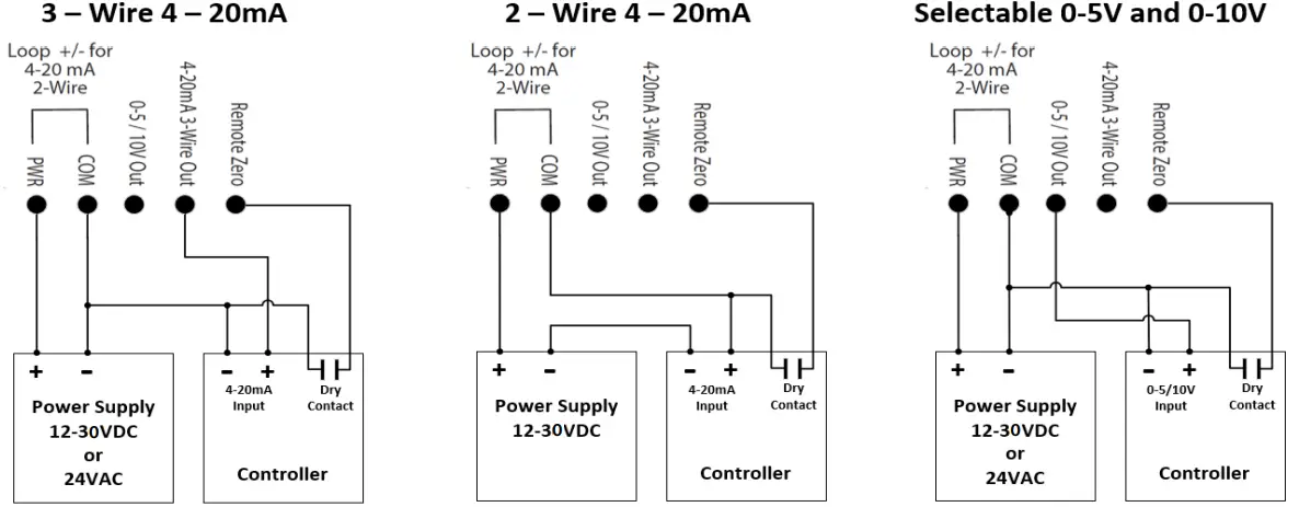
- Move output selection switch to select appropriate analog output (4-20mA 2 -Wire or 3-Wire configurations or 5V/10V.)

Vout Iout(mA) Position 0-5VDC 3-Wire Top 0-10VDC 3-Wire Middle – 2-Wire Bottom - Move rotary range selection dial to the desired pressure ge position.

Range Selection Dial Position
5” WC
15” WC
40” WC
1250 Pa
3750 Pa
10000 Pa
0 0.10 0.25 1.00 25 50 250 1 0.25 0.50 2.50 50 125 625 2 0.50 1.00 5.00 125 250 1250 3 1.00 2.50 8.00 250 625 2000 4 1.50 3.00 10.00 375 750 2500 5 2.00 4.00 15.00 500 1000 3750 6 2.50 5.00 20.00 625 1250 5000 7 3.00 8.00 25.00 750 2000 6250 8 4.00 10.00 30.00 1000 2500 7500 9 5.00 15.00 40.00 1250 3750 10000 - Use the configuration switches to adjust the device settings.

- Plumb air lines to sensor hose barbs(Accepts 1/8” & 1/4” ID tubing). High (+) and low (-) ports are labeled on the sensor.
- Wire sensor for voltage or current output as shown in the wiring diagrams.
- Recommendation: Apply power to sensor. With no pressure applied, press the ZERO SET button for 2-seconds. (For best results, temporarily connect high and low pressure ports together while zeroing.)

LED STATUS/INDICATION
- LED indicator will flash every 5 seconds for normal operation.
- LED indicator will rapidly flash when applied pressure greater than 110% of selected range.
- LED indicator will rapidly flash momentarily when zeroing process is complete.
TROUBLESHOOTING
| TROUBLESHOOTING | |
| Symptom | Solution |
| No output | Check wiring. Ensure power supply meets requirements. |
|
Pressure reading error | Verify control panel software is configured for correct output scaling. |
| Verify switch settings. | |
| Verify tubing is not pinched or leaking. | |
| Possible contamination. Ensure sensor is used only on dry air or nitrogen. | |
WIRING DIAGRAMS
TYPICAL APPLICATIONS
Velocity: Use a pitot tube and plumb high (+) port to total pressure (Pt) connection and low (-) port to static pressure (Ps) connection to directly read Pt-Ps = Pv. Apply correction constant provided by pitot tube manufacturer.
Duct Static: Install a static pressure pickup tube approximately 2/3 of the way down the discharge air duct and plumb to high (+) port for positively pressurized ducts.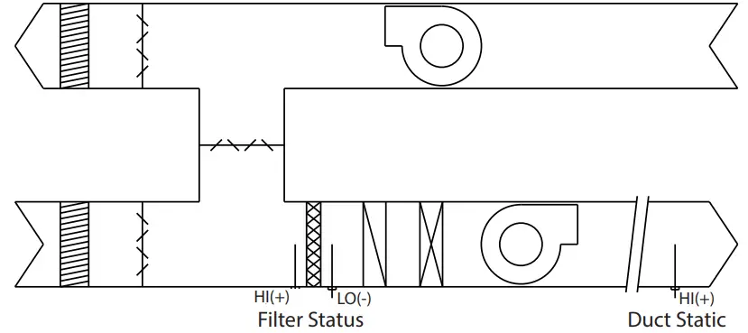
SPECIFICATIONS
| Power Supply | 12-30VDC/24VAC (1), 30mA max. | |
| Output type | Selectable outputs | 4-20 mA loop powered, 4-20 mA 3-wire, 0-5VDC, 0-10VDC |
|
Output scaling | Max range (Selectable sub ranges) | 0-5” (0.1/0.25/0.5/1/1.5/2/2.5/3/4/5”wc), 0-1250Pa (25/50/125/250/375/500/625/750/1000/1250 Pa) 0-15” (0.25/0.5/1/2.5/3/4/5/8/10/15”wc) 0-3750Pa (50/125/250/625/750/1000/1250/2000/2500/3750 Pa) 0-40” (1/2.5/5/8/10/15/20/25/30/40”wc) 0-10000Pa (250/625/1250/2000/2500/3750/5000/6250/7500/10000 Pa) |
| Operating Temperature | Operating range | -4 to 140F (-20 to 60ºC) |
| Compensated range | -4 to 140F (-20 to 60ºC) | |
| Media compatibility | Dry, oil-free air, N2 | |
| Sensor Type | MEMS silicon piezoresistive; precision calibrated | |
| Accuracy | ±1.0% of selected range (combined linearity and hysteresis) | |
| Zero Tolerance | Included in accuracy specification | |
| Span Tolerance | ±1.0% | |
| Zero Drift (1 year) | 0.004”wc/year max. 0.4% for units >0.5”wc | |
| Auto-zero input | Push-button and contact closure | |
| Sensor Performance | Thermal Shift (Zero and Span) | 0.02% FSO/ºC (0.01%FSO/ºF) measured from 22ºC (72ºF) |
| Overpressure | up to 5” models: 41.5”wc; 10” models: 133”wc; 25” models: 332”wc | |
| Max Static Line Pressure | up to 5” models: 41.5”wc; 10” models: 133”wc; 25” models: 332”wc | |
| Burst Pressure | up to 5” models: 83”wc; 10” models: 166”wc; 25” models: 415”wc | |
| Position Sensitivity | Non-position sensitive | |
| Auto-zero input | Push-button and N.O. contact closure | |
| Response Rate | Selectable | Fast = 2 seconds, slow = 8 seconds |
| Agency | Compliance | CE, RoHS |
| Material | UL94 5VB, ABS | |
| Enclosure | Environmental | NEMA 4X |
| Dimensions | 4.0”h x 3.7”w x 2.1”d |
- senvainc.com
- 1-866-660-8864
- 1825 NW 167th Place
- Beaverton Oregon 97006


