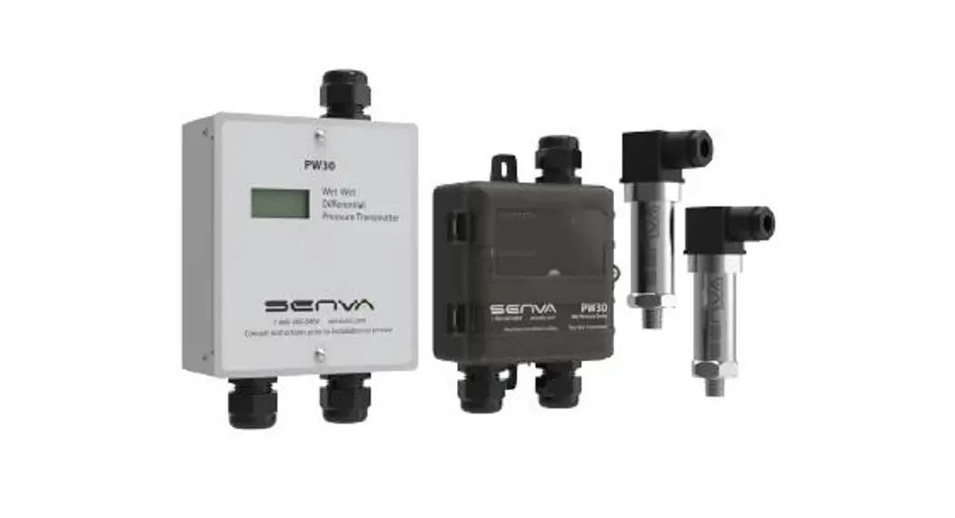
![]() PW30 Wet Pressure Transmitter
PW30 Wet Pressure Transmitter
Instruction Manual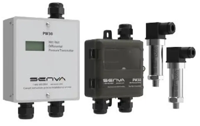 INSTALLATION INSTRUCTIONS
PW30
Wet-Wet Pressure Transmitter
PW30 Wet Pressure Transmitter
IMPORTANT WARNINGS
- Only qualified trade installers should install this product
- This product is not intended for life-safety applications
- Do not install in hazardous or classified locations
- The installer is responsible for all applicable codes
- De-energize power supply prior to installation or service
PRODUCT APPLICATION LIMITATION:
Senva products are not designed for life or safety applications. Senva products are not intended for use in critical applications such as nuclear facilities, human implantable device or life support. Senva is not liable, in whole or in part, for any claims or damages arising from such uses.
IMPORTANT!
-Do NOT exceed gauge pressure rating of sensor.
-Use ONLY Senva gauge pressure sensors provided with your PW transmitter to obtain the specified transmitter accuracy.
-Follow instructions step by step to ensure proper setup.
INSTALLATION
1. Identify PWC sensors A & B and their respective PSIG rating.
If the expected system gauge pressure exceeds the PSIG rating on the PWT sensors call factory and DO NOT proceed with install.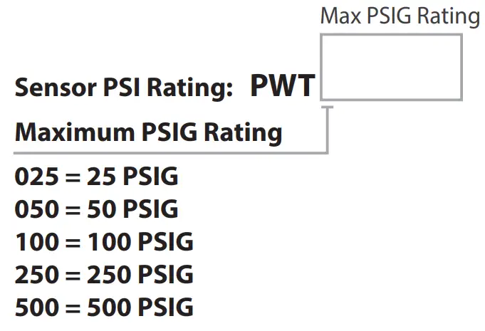 2. Plumb PWT sensors to media. Sensor A is intended for supply pressure and sensor B is intended for return pressure of the system. Plumb PWT sensors to the side or top of pipe, as plumbing to the bottom will cause sediment to settle and could clog or affect sensor accuracy. It is advisable to use a single wrap of PTFE tape on the PWT sensors threads, or other thread sealing alternative, to improve sensor accuracy.
No bypass valve manifold is necessary. Use only Senva gauge pressure sensor elements provided with your transmitter. Optional shutoff valves are available – Senva recommends closing service valves when flushing system to prevent containments and water hammer from damaging PWT sensing elements.
4. Run the appropriate length cables between the PW transmitter and PWT sensors.
Senva recommends 22AWG stranded, 4 conductor shielded cable to wire between the PW transmitter and PWT sensors.
5. Loosen the top screw on each PWT sensor and remove the terminal block for wiring as shown below: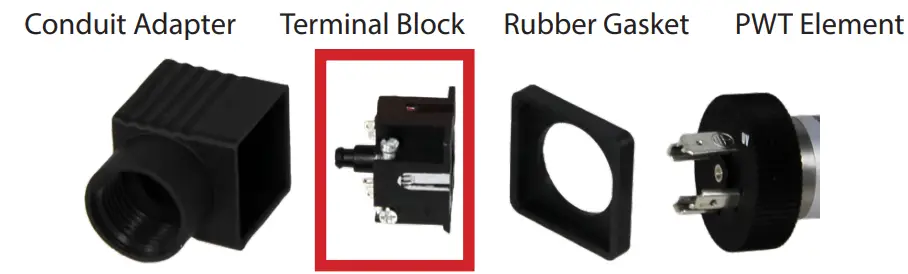 6. Run the cable through the conduit adapter and connect the wires to the PWT terminal block. Note that the conduit terminal block is numbered and color coded to match the terminal label colors on the PW transmitter.
IMPORTANT: DO NOT connect the shield at the PWT sensor element end. The shielding should only be connected to the ground terminal at the PW transmitter end.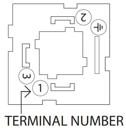
| Pin | Connection | Color |
| 1 | PWR | Red |
| 2 | GND | Green |
| 3 | Signal (S1/S2) | White |
| Shield | Black |
7. Reassemble the PWT conduit adapter and terminal block.
Place the rubber cover back on the conduit adapter and plug the adepter onto the PWT sensor. Tighten the assembly screw. DO NOT attempt to plumb or tighten the PWT sensors while wires are attached, as you run the risk of pulling wires from cable attachments.
8. Wire PWT sensors A & B to the PW Transmitter terminals labeled A & B respectively. See above table if wiring a pre ordered cable length for color coordination. For strain relief, tighten cable glands.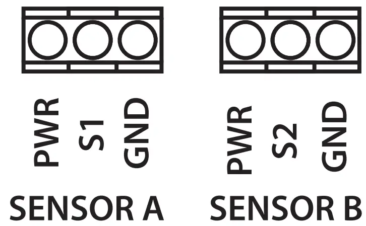 IMPORTANT: Shielding should be connected to the shield (
![]() ) Terminal at the PW transmitter end, and left unconnected at the PWT sensor element end.
) Terminal at the PW transmitter end, and left unconnected at the PWT sensor element end.
9. Connect conduit fittings to the PWT sensors and PW transmitter. Use water tight fittings if required by your installation conditions.
10. Wire PW transmitter for voltage or current output as shown (Remote zero wiring is optional):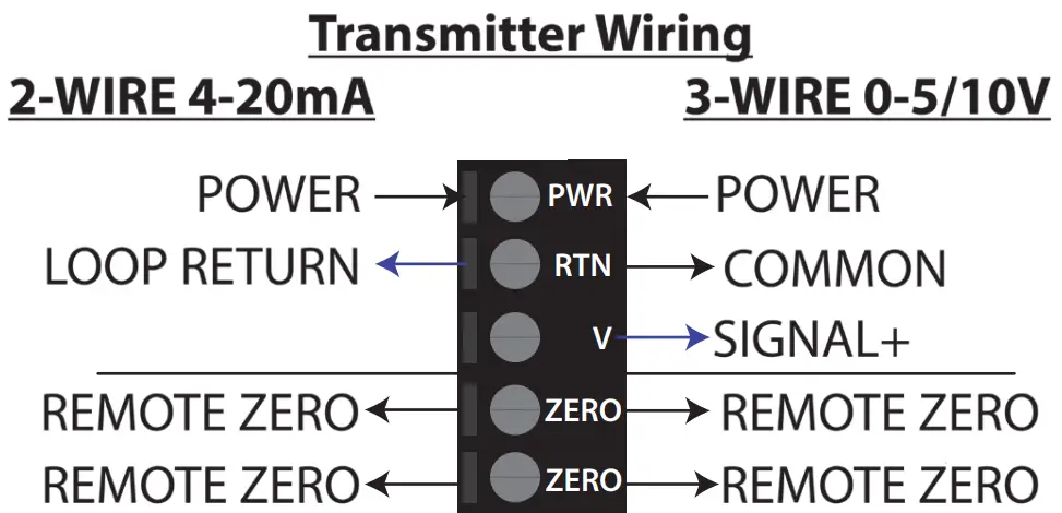 11. Select 20mA, 5V or 10V output using OUTPUT switch based on wiring configuration.
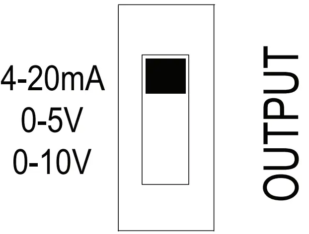 12. Configure output range and sensor PSIG using DIP switches 1-7. DIP 1-3 set the sensor PSIG corresponding to the PWT ordered. DIP 4-7 are used to set the desired output signal range. Both use the binary code system outlined in the table.
PW Transmitter DIP Switch Configuration:
DIP Switch Settings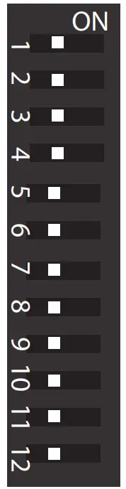
| DIP | Function | LEFT | RIGHT |
| 1 | SENSOR2 | 0 (off) | 1 (on) |
| 2 | SENSOR1 | 0 | 1 |
| 3 | SENSOR0 | 0 | 1 |
| 4 | RANGE3 | 0 | 1 |
| 5 | RANGE2 | 0 | 1 |
| 6 | RANGE1 | 0 | 1 |
| 7 | RANGE0 | 0 | 1 |
| 8 | Units | KPA | PSI |
| 9 | UNI/BI | BI | UNI |
| 10 | MODE | FAST | SLOW |
| 11 | SWAP | B-A | A-B |
| 12 | ABS | ABS | +/- |
| DIP | Binary | SENSOR (PSIG) |
| 1-3 | 000 | TEST |
| 001 | 15* | |
| 010 | 25* | |
| 011 | 50 | |
| 100 | 100 | |
| 101 | 200* | |
| 110 | 250 | |
| 111 | 500 | |
| DIP | Binary | RANGE (PSID) |
| 4-7 | 0000 | 0-1 |
| 0001 | 0-2 | |
| 0010 | 0-5 | |
| 0011 | 0-10 | |
| 0100 | 0-15 | |
| 0101 | 0-20 | |
| 0110 | 0-25 | |
| 0111 | 0-30 | |
| 1000 | 0-40 | |
| 1001 | 0-50 | |
| 1010 | 0-75 | |
| 1011 | 0-100 | |
| 1100 | 0-125 | |
| 1101 | 0-150 | |
| 1110 | 0-250 | |
| 1111 | 0-500 |
*15, 25 and 200 PSIG sensors are not offered by senva
13. Inspect LCD for readings. LCD toggles between sensor A reading, sensor B reading, and PSID reading. Sensor A reading is indicated by a tick mark on the top left of LCD. Sensor B reading is indicated by a tick mark at the bottom left of LCD. PSID reading is displayed without any mark at the left of the LCD.
O/R symbol will flash in bottom center of LCD if differential pressure reading is over range. If this occurs, select larger PSID range to avoid clipping of readings.
14. Check remaining DIP switch (8-12) configurations for additional setup options:
Units: LCD will display readings in PSI or kPa. LCD will indicate PSI or kPa at top of screen.
UNI/BI: PW transmitter can be setup in Uni or Bi directional mode.
Bi-Directional Mode Example range set at 100 PSID:
| A | B | DP | OUTPUT |
| 100 | 0 | +100 | 20mA/10V/5V |
| 100 | 50 | +50 | 16mA/7.5V/3.75V |
| 50 | 50 | 0 | 12mA/5V/2.5V |
| 50 | 100 | -50 | 8mA/2.5V/1.25V |
| 0 | 100 | -100 | 4mA/0V/0V |
MODE: In ‘Slow Mode’ the output returns a reading averaged over 64 samples. In ‘Fast Mode’ the output returns the most recently calculated reading for PSI.
SWAP: If PWT sensor A was plumbed to the return (low) side and PWT sensor B was plumbed to the supply (high) side instead of re-plumbing the sensors, the Port Swap can be utilized without a physical reconfiguration.
ABS: In Absolute Mode, values will always be reported positive.
15. To custom zero the device (optional), hold down the zero button for 5 seconds (until the LCD blinks once). Hold down for 10 seconds (until LCD blinks twice) to reset/clear the zero value.
16. Seal remaining conduit knockouts on PW transmitter.
SENVA TECHNICAL SUPPORT
Need further assistance? Call our toll-free number for live technical support: (866) 660-8864 or feel free to email us at [email protected]
DIMENSIONS
PW30W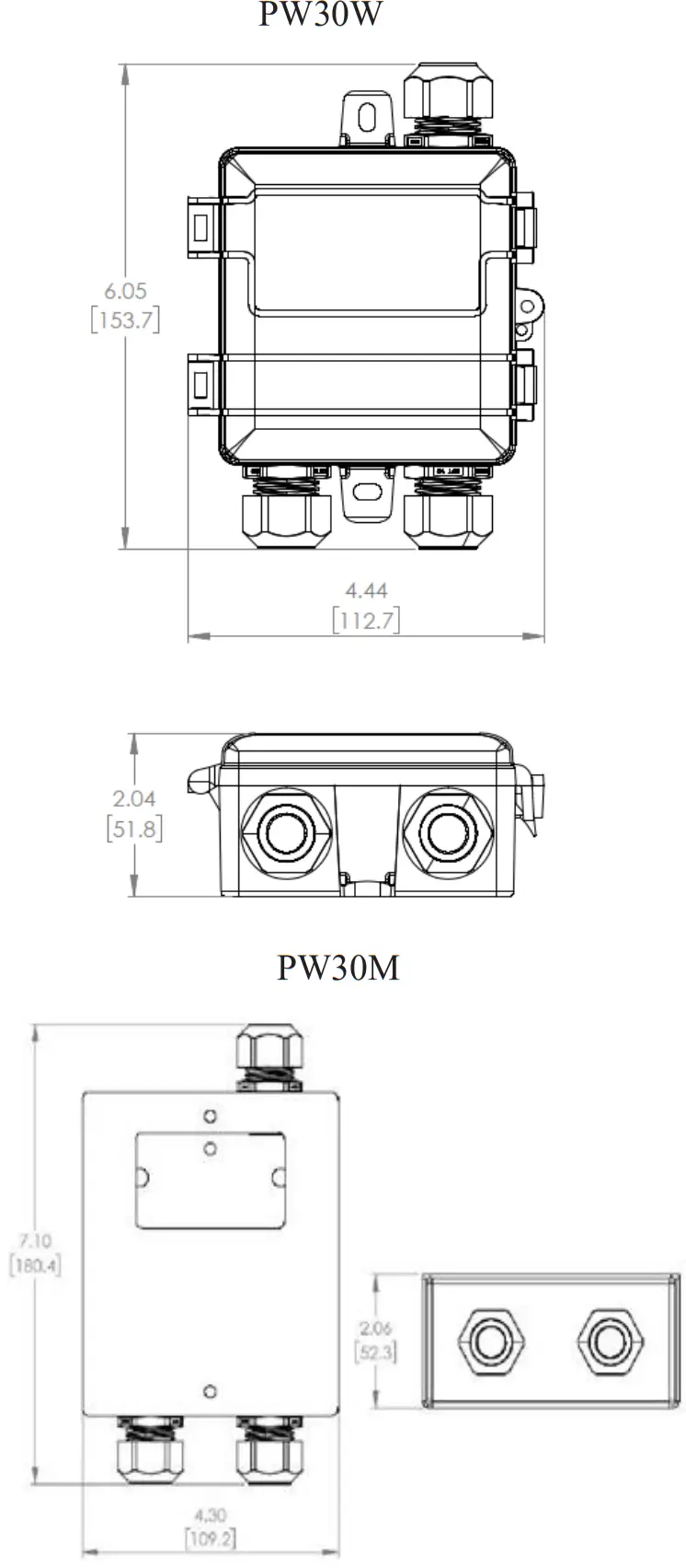
SPECIFICATIONS
| Power supply | Voltage output mode (0-5v) Voltage output mode (0-10v) Current (4-20mA) output mode | 12-30VDC/24VAC (1), 20mA max. 13-30VDC/24VAC required for 10V FS output 15-30VDC(0 ohm)/16-30VDC (250 Ohm)/ 18-30VDC (500 Ohm) , 20mA max. | |
| Outputs | Switch selectable | 2-wire 4-20mA, 3-wire 0-5V/10V | |
| Operating Temperature | Transmitter | -22 to 158oF (-30 to 70C) | |
| Media Compatibility | Type Temperature | Water, other 316 SS compatible media (316L diaphragm) 32 to 250oF (0-125oC) | |
| Zero adjustment | Automatic | Pushbutton, Remote zero Press button for 5 seconds to re-zero Hold for 10 seconds to restore factory settings | |
| Sensor Type | Micro-machined silicon strain gauge | ||
| PW Transmitter Accuracy(2) Range according to PSID table in PW Transmitter DIP Switch Configuration table | Sensor PSIG | 2% Accurate ranges | 1% Accurate ranges |
| 25 | 0-1 / 0-2 PSID | 0-5 / 0-10 / 0-15 / 0-20 / 0-25 PSID | |
| 50 | 0-10 / 0-15 PSID | 0-20 / 0-25 / 0-30 / 0-40 / 0-50 PSID | |
| 100 | 0-15 / 0-20 / 0-25 / 0-30 PSID | 0-40/ 0-50 / 0-75 / 0-100 PSID | |
| 250 | 0-30 / 0-40 / 0-50 PSID | 0-75 / 0-100 / 0-125 / 0-150 / 0-250 PSID | |
| 500 | 0-75 / 0-100 / 0-125 PSID | 0-150 / 0-250 / 0-500 PSID | |
| Sensor Performance | Accuracy | < +/-0.25% BFSL | |
| Stability (1 year) | +/-0.2% FS, typ | ||
| Over-range protection | 200% rated pressure | ||
| Pressure Cycles | > 100 Million | ||
| Compensated Range | 14 to 158oF (-10-70oC) | ||
| Temperature Compensation %FS/C | Zero, <+/-0.03(<100kPa), <+/-0.02( >100kPa) Span,<+/-0.03(<100kPa), <+/-0.02( >100kPa) | ||
| Vibration | 10G peak, 20 to 2000 Hz. | ||
| Enclosure, PW30M | Construction | Powder coated steel | |
| Rating | NEMA 3R | ||
| Enclosure, PW30W | Construction | PC/ABS | |
| Rating | NEMA 4X | ||
| Enclosure, PWT[xxx] Sensor | Construction | Stainless Steel, 304, 1/4” MNPT, PG9 Conduit Fitting | |
- One side of transformer secondary is connected to signal common. Dedicated transformer is recommended.
- Because of lower accuracy, it is not factory recommended to use an output range less that 10% of the total sensor PSIG.
TROUBLESHOOTING
| Symptom | Solution |
| No output | Check wiring. Ensure power supply meets requirements |
| Pressure reading error | Verify control panel software is configured for correct output scaling |
| Verify switch and jumper settings | |
| Device will not zero | Hold ZERO button for full 5-seconds until LCD blinks once |
| Continue holding ZERO button for 10-15 seconds, until LCD blinks twice, to restore factory settings |
Issued1/6/2021 Document #152-0412-0C![]()


