![]() G Series AC, Solar Cabinet
G Series AC, Solar Cabinet
Installation Guide
Warnings and Precautions
The following symbols indicate important safety warnings and precautions throughout this guide:
| WARNING indicates that serious bodily harm or death may result from failure to adhere to the precautions. | |
| CAUTION indicates that damage to equipment may result if the instructions are not followed. | |
| NOTE suggests optimal conditions and provides additional information. |
1.1 Warranty Disclaimer
This manual will familiarize you with the features, operation standards, and installation of Carmanah’s G Series Applied Information (AI) Integration Kit. Failure to comply with the use, storage, maintenance, installation or placement instructions detailed in this manual could void the warranty.
1.2 Standards
Perform all installation, wiring, grounding and maintenance in conformance with local building and electrical codes. Adherence to the National Electrical Code (NEC) is mandatory to comply with any certification markings.
Non-adherence to code may void the warranty.
1.3 Safety and Usage Precautions
| Batteries are shipped fully charged. Use extreme caution when handling the batteries as they can generate hazardous short-circuit currents. Remove all jewelry (bracelets, metal-strap watches, etc.) before entering the cabinet. | |
| Solar panels produce DC electricity when exposed to light and can therefore produce an electrical shock or burn. To render solar panels inoperative, remove them from sunlight or fully cover their front surface with an opaque material. | |
| Before lifting any heavy or bulky equipment, ensure the load is secured so moving parts do not shift, and that it can be lifted as far as needed without back strain or loss of grip. Installation may require more than one person. | |
| Ensure the equipment is not powered during installation and wiring of the system. | |
| Recheck all completed wiring for proper polarity prior to energizing the system. | |
| Changes or modifications to Carmanah equipment not expressly approved by Carmanah could void both the user’s authority to operate the equipment and the warranty. | |
| Product can have sharp edges. Accidental movement of hinged components can cause injury. |
1.4 Applications
For Carmanah R829-G and R247-G systems, the G Series AI Integration Kit allows for remote system monitoring, scheduling and control. With Carmanah R820-G and SC315-G Rectangular Rapid Flashing Beacon (RRFB) systems, the G Series AI Integration Kit allows remote system monitoring only.
System Components
The G Series Applied Information (AI) Integration Kit consists of the following items:
| 1. Harness, AI 16-pin to terminal block (1) 2. Door switch and harness, G Series cabinet (1) 3. Adapter, 90°, SMA male to SMA female (2) 4. Screw, security, pin-in hex, #10-32 x 0.5″ (2) 5. Screw, machine, #8-32 x 3/8″, Phillips (4) 6. Screw, machine, #10-32 x 3/8″, Phillips (2) 7. Washer, flat, #10 (4) | 8. Washer, lock, #10 (2) 9. Standoff, #10-32 x 5/8″, female, aluminum (2) 10. Tie mount, push barb (2) 11. Cable tie, mounting base, ¾ x ¾” (3) 12. Cable tie, 4″ (10) 13. Cable tie, 7″, #8 screw mount (1) 14. Install guide, AI Integration Kit, G Series (1) 15. Adapter, harness, AI 070B to 030/070C (1) |
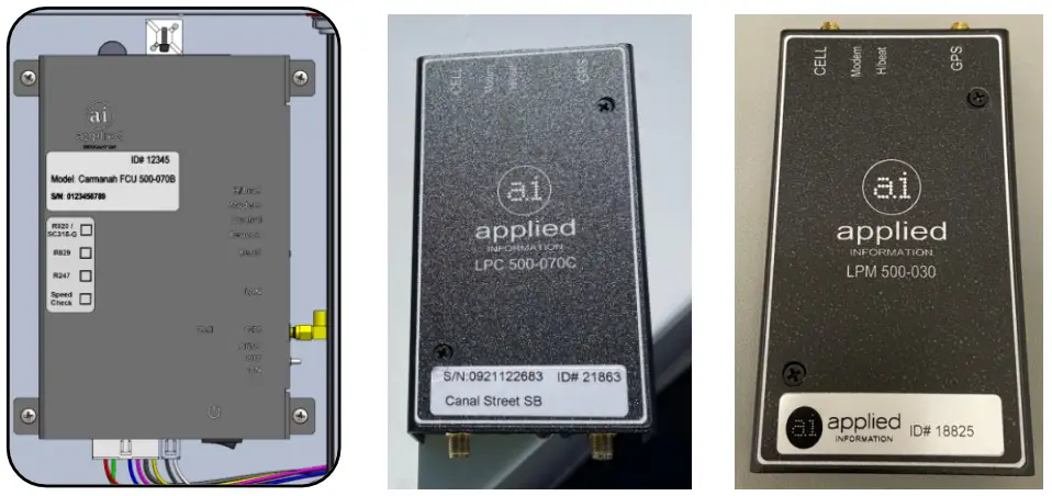
![]() The Applied Information AI-500-070B, AI-500-070C, and AI-500-030 (monitoring only) are supported with SPEEDCHECK-15/18 systems. Modem supplied separately.
The Applied Information AI-500-070B, AI-500-070C, and AI-500-030 (monitoring only) are supported with SPEEDCHECK-15/18 systems. Modem supplied separately.
Tools and Materials Required
The following tools and materials may be required to install the AI Integration Kit into your G Series system:
- Drill and ½” drill bit
- Deburring tool or similar
- Crescent wrench
- Side cutters
- Multi-bit screwdriver
- Electrical multimeter
Door Switch (optional):
- Loctite 220 thread locker or similar
- ANSI #9 drill bit (0.196″ diameter)
- 5/32″ tamper-resistant hex screwdriver bit
G Series Cabinet Installation
4.1 Antenna
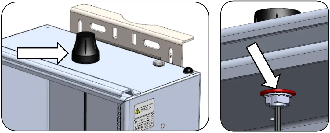
- Remove power to the system. For AC-powered systems, turn off the circuit breaker in the cabinet and for solar-powered systems remove the battery and solar fuses.
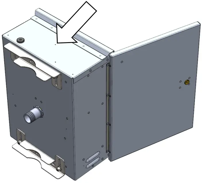
- Use the indentation in the center of the cabinet to locate the tip of the drill bit. Drill a ½” hole on top of the enclosure. Deburr hole and remove all aluminum chips.


Ensure the equipment is not powered during installation. Recheck all wiring prior to energizing the system. 
Ensure all metal chips are removed to prevent system damage caused by short circuits. Ensure that no burrs are present that would prevent the antenna from making a good seal with the top of the cabinet. - Route antenna coax connector cables into enclosure hole and through plastic washer, lock washer, and nut. Tighten nut securely using crescent wrench.

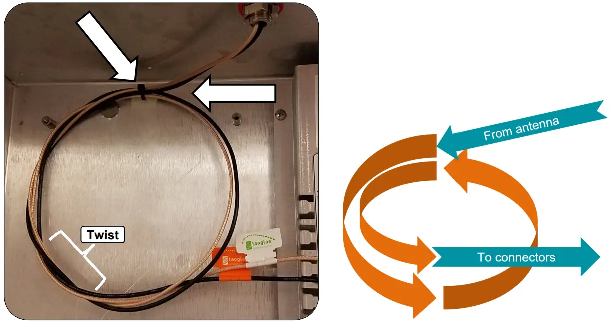
- Install one cable tie base in the location noted below.
- Route coax cables from antenna to cable tie mount and loop 1.5 times in a counter-clockwise direction. Fasten coax to cable tie mount with one cable tie. Twist the cable so the connector ends exit to the righthand side.

4.2 Door Switch Kit (Optional)
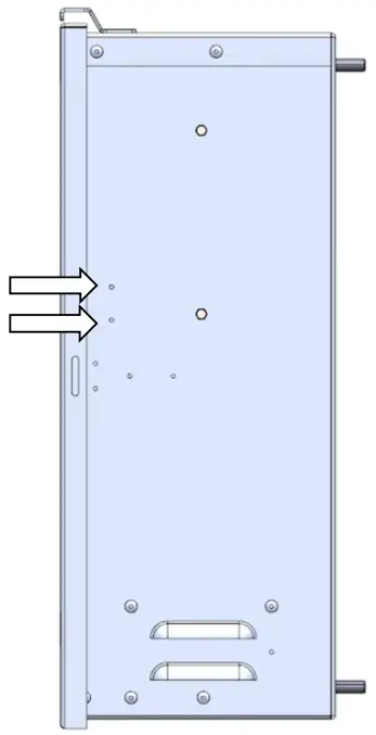
- Use the indentation marks below to locate the drill holes.
- Drill two 0.196″ diameter holes as noted using a #9 ANSI drill bit.
- Deburr the holes on the outside and inside to remove all aluminum chips.
 Ensure all metal chips are removed to prevent system damage caused by short circuits.
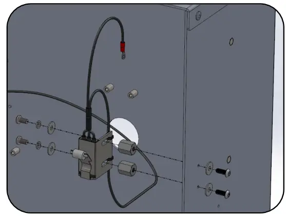
 - Apply Loctite 220 thread locker to two standoffs.
- Assemble standoffs to the inside of the cabinet using two security screws and two flat washers.
- Fasten the long wire from door switch to slots with two cable ties. Leave loose/untrimmed for now.
- Install door switch to the standoffs using two screws, two lock washers, and two flat washers.
- Center switch front/rear in slots and tighten. No Loctite thread locker is required for this step.

 The terminal on the end of the long door switch wire gets installed into the Applied Information (AI) harness connector in a later step.
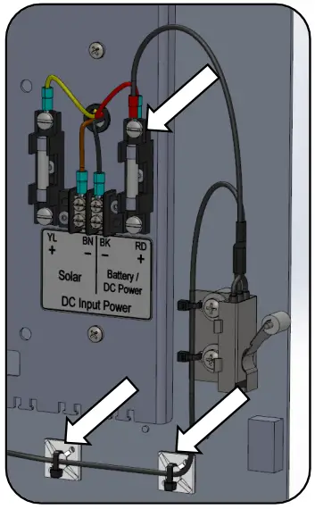
 - Install ring terminal from door switch onto top Battery/DC Power RD + fuse holder terminal.
- Install two cable tie bases as shown below. Fasten wires from door switch to the two cable tie bases.
Leave loose/untrimmed for now.
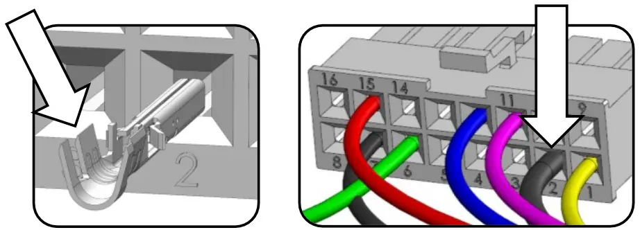
- Insert terminal from door switch harness into Position 2 of AI harness connector. Orient terminal same way as other terminals present in connector. Tug to confirm it’s fully inserted. Cable ties will be tightened and trimmed at the end of Section 4.3.
 Connector terminal shown uncrimped. Crimp wings will be bent over wire strands.
4.3 AI 500-070B Field Control Unit (FCU)
- Install two cable tie mounts. Press into ¼” holes.
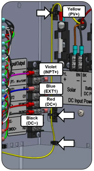
- Install the AI harness wires to the terminals as follows:
a. Yellow → PV+ (over existing terminal)
b. Violet → INPT+
c. Blue → OUT1
d. Red → DC+
e. Black → DC- - Secure yellow wire to mounts & location shown with three cable ties. Leave loose/untrimmed for now.

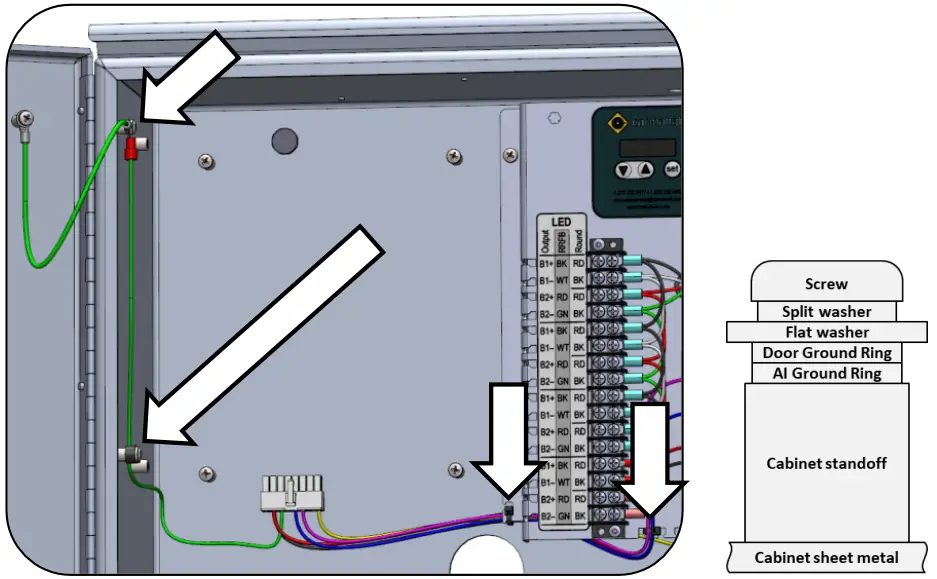
- Install green wire ring terminal from AI harness along with door ground ring terminal in the order shown below.
- Route ground wire down and fasten with screw mount cable tie. Remove existing cable tie if present and add existing wires to new cable tie.
- Fasten harness wires using two cable ties. Include door switch wire if present.

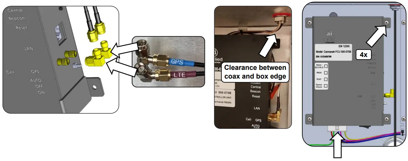
- Thread two 90° coax adapters onto antenna connectors. Orient as shown (facing upward when installed into cabinet).
- Fasten AI-500-070B into cabinet using four screws.
- Thread coax adapters onto AI-500-070B connectors. Match GPS & LTE labels on antenna harness & AI-500-070B (Cell closer to front, GPS closer to back).
- Route the coax cables between the AI-500-070B and antenna neatly. Avoid sharp bends in the coax cable. Keep coax cable away from sharp edges.
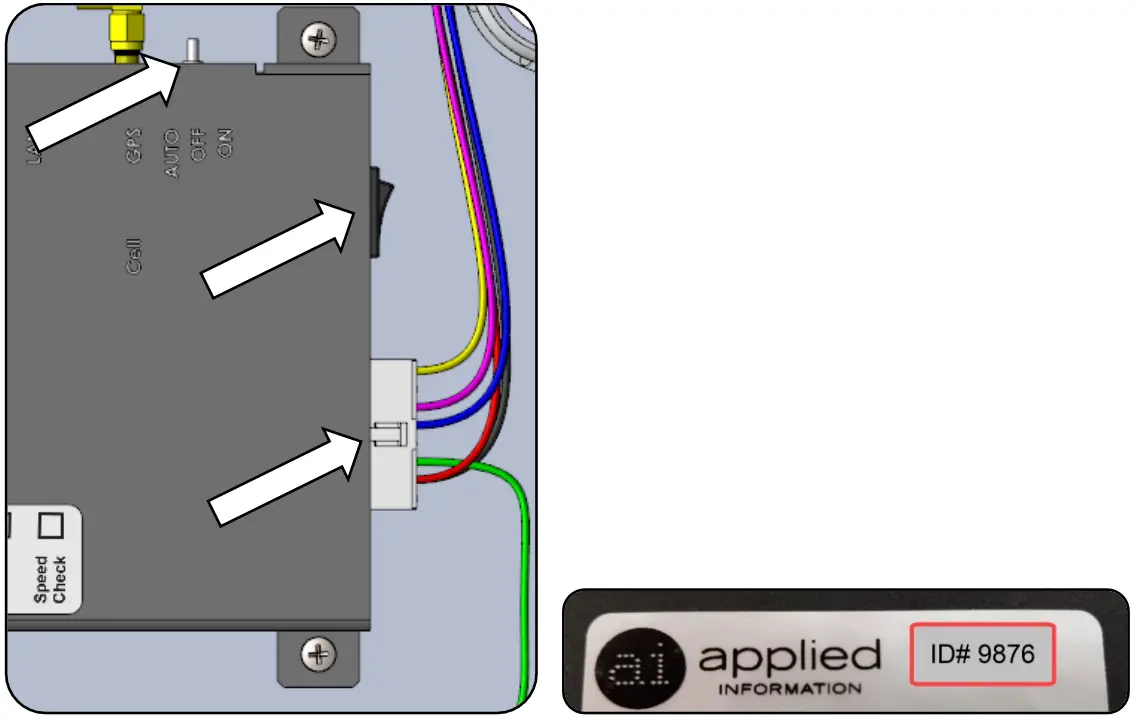
- Mate 16-pin connector to AI-500-070B connector. With all cables installed, tighten and trim all cable ties.

4.4 Testing AI-500-070B
- Ensure AI serial number has been activated.
- For SC315-G or R820 systems set toggle switch to “OFF”. In all other cases set to “AUTO”.
- Ensure connector is properly mated on the bottom of the AI-500-070B.
- Confirm correct wiring and power-up system by connecting the DC power (system fuses or switching on breaker) and turning on the AI power switch.
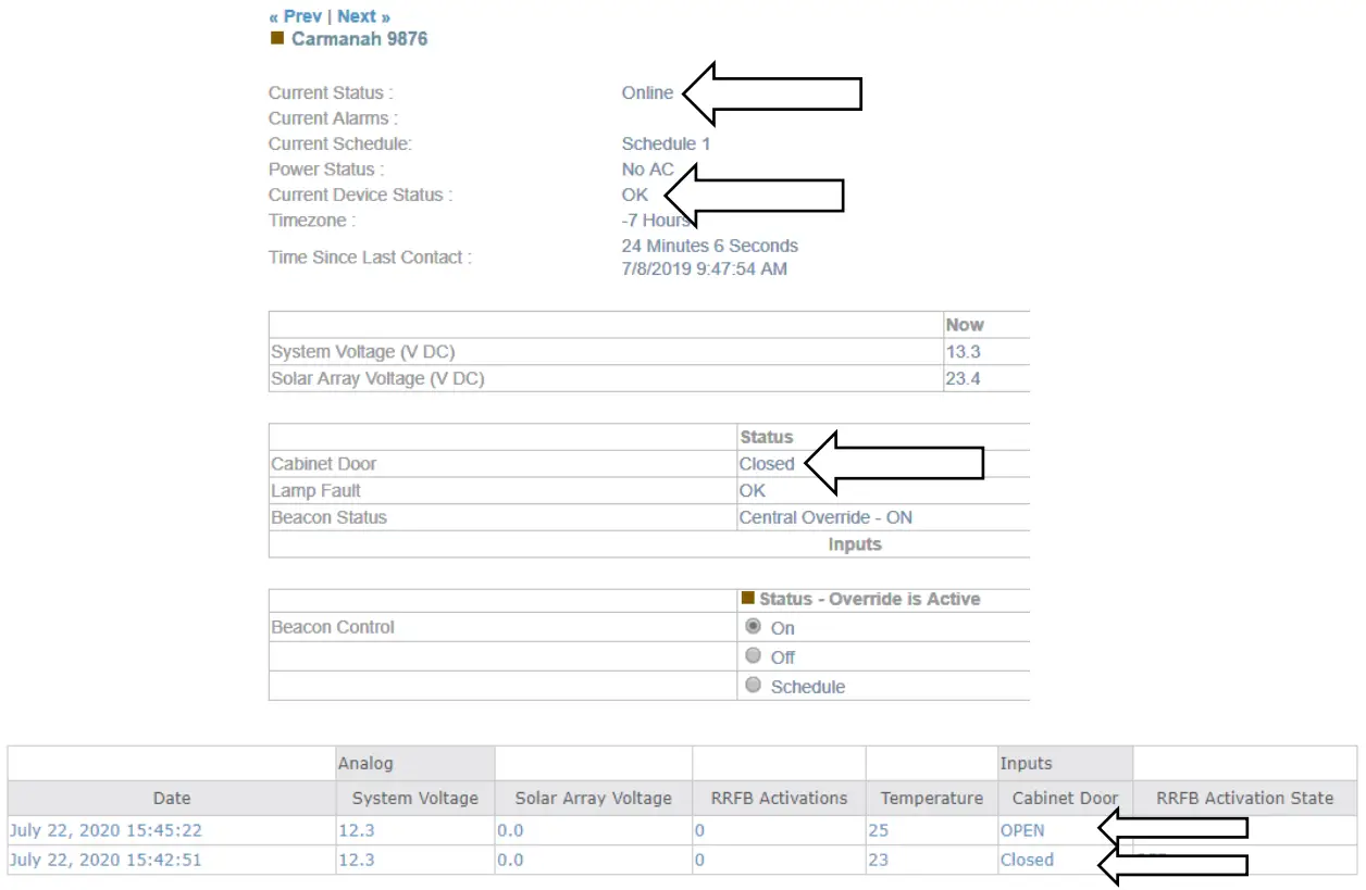
- On your PC, open a browser and navigate to the Glance website:
a. glance.appinfoinc.com - Log in using the credentials provided by AI or the distributor you purchased the equipment from.
- On the upper left side of the browser, select the device name that matches the Device ID (the ID number labelled on the AI-500-070B).
 Ensure the equipment is not powering during installation. Recheck all wiring prior to energizing the system.
 - Ensure that the “Current Status” indicates “Online”.
- Ensure “Current Device Status” is “OK”.
- If the door switch sensor is installed, ensure that the “Cabinet Door” status reflects the current position of the door. Open and close the door to change the switch state and confirm Glance reflects the change.
a. Door open = Open
b. Door closed = Closed - Contact Applied Information to arrange the firmware in the AI unit to be programmed correctly, if this hasn’t already been done.
c. Phone: 678.830.2170
d. Email: [email protected]
e. Web: appinfoinc.com If testing indoors where there is no GPS signal, this may result in a device status of “No GPS Lock”. R829 school zone application shown above.
Appendix A – AI-500-070C/AI-500-030 Low Power Devices
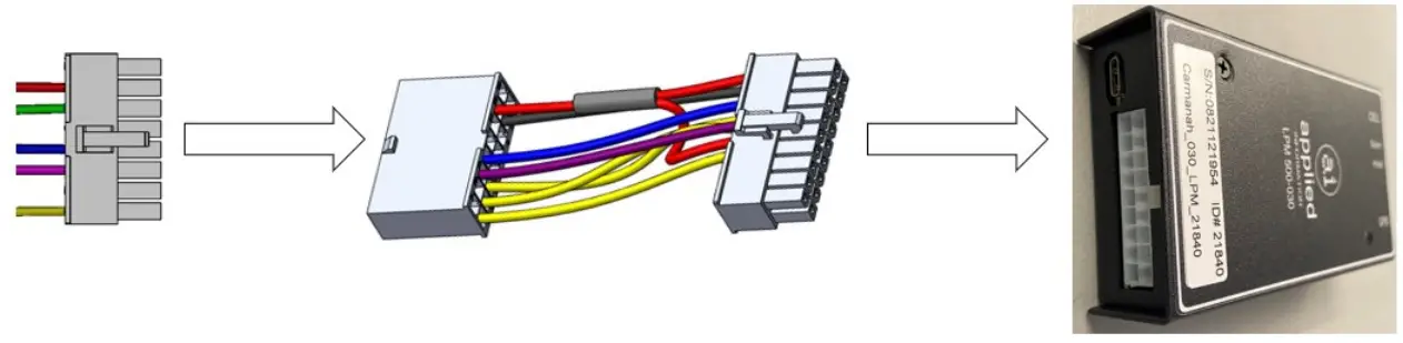
For systems that will contain the AI-500-070C/AI-500-030, Carmanah includes an adapter harness to go from the AI-500-070B harness to the AI-500-070C/AI-500-030 low power device.
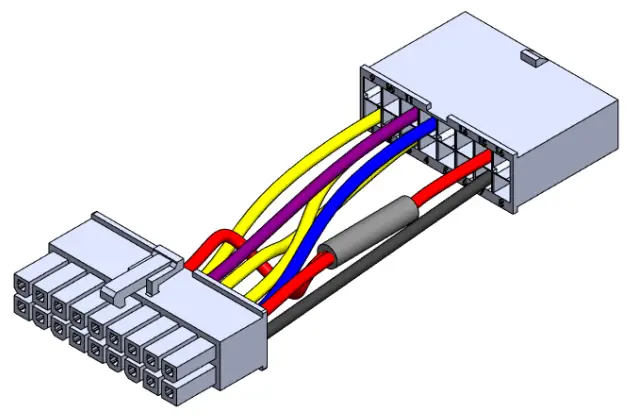
The supplied AI-500-070B (16-pin) harness will connect to the adapter harness (16-pin to 18-pin). The 18-pin end of the adapter harness then connects to the AI-500-070C/AI-500-030.
The following monitoring/control parameters will be available with this harness and adapter configuration in a G Series system:
- Solar panel voltage monitoring (solar systems only)
- System voltage monitoring (AC systems only)
- Battery voltage monitoring (solar systems only)
- Cabinet door monitoring (if door switch installed)
- Beacon monitoring
- Beacon control and scheduling (AI-500-070C only)
- Knockdown monitoring
![]() The beacon control wire (violet; INPT+) should be disconnected and capped off for systems using the AI-500-030. See Section 4.3 for more information.
The beacon control wire (violet; INPT+) should be disconnected and capped off for systems using the AI-500-030. See Section 4.3 for more information.
Follow the instructions provided by Applied Information for installing the AI-500-070C/AI-500-030 or contact their email support at [email protected].
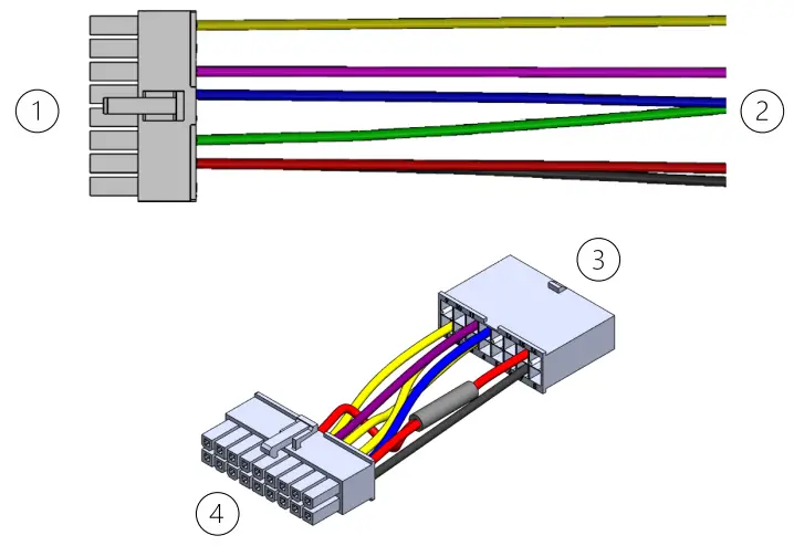
- To adapter harness; #3
- To G Series terminal block (see Section 4.3)
- To AI-500-070B harness; #1
- To AI-500-070C/AI-500-030 device
Door switch:
- See Section 4.2
Solar/AC systems:
- See Section 4.3
![]() © 2022 Carmanah Technologies Corporation
© 2022 Carmanah Technologies Corporation
Technical Support:
Email: [email protected]
Toll Free: 1.877.722.8877 (US & Canada)
Worldwide: 1.250.380.0052
Fax: 1.250.380.0062
Web: carmanah.com
Carmanah Technologies Corp.
250 Bay St, Victoria, BC V9A 3K5, Canada
1.250.380.0052
[email protected]
carmanah.com
References
 Applied Information | Smart City and Connected Infrastructure Expertise
-
Systems for Traffic Beacons and Signs | Solar LED Beacons | Carmanah
 glance.appinfoinc.com
-
Applied Information | Smart City and Connected Infrastructure Expertise
-
glance.appinfoinc.com/
-
Systems for Traffic Beacons and Signs | Solar LED Beacons | Carmanah


