![]() VCIMD-14932 November 2021
VCIMD-14932 November 2021
Spence Type D34 Water Pressure Reducing Valve
Instruction Manual
Spence Type D34 Water Pressure Reducing Valve
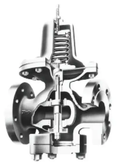
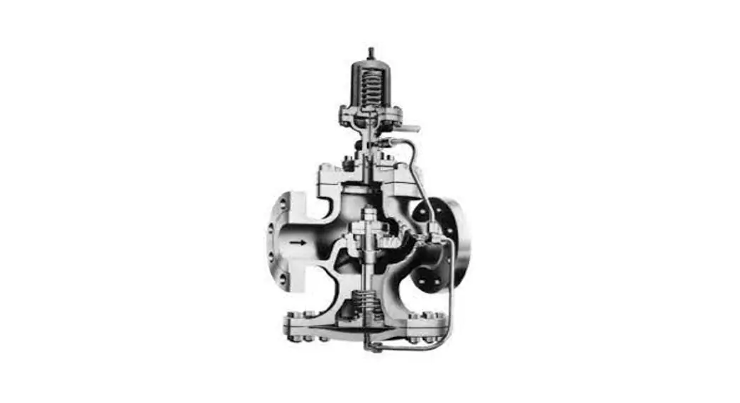
Figure 1. Type D34 Pressure Reducing Valve
![]() WARNING
WARNING
Failure to follow these instructions or to properly install and maintain this equipment could result in an explosion, fire and/or chemical contamination causing property damage and personal injury or death.
Emerson Pressure Reducing Valve must be installed, operated and maintained in accordance with federal, state and local codes, rules and regulations and Emerson Process Management Regulator Technologies, Inc. (Emerson) instructions.
If the valve vents gas or a leak develops in the system, service to the unit may be required. Failure to correct trouble could result in a hazardous condition.
Installation, operation and maintenance procedures performed by unqualified personnel may result in improper
adjustment and unsafe operation. Either condition may result in equipment damage or personal injury. Only a qualified person shall install or service the Type D34 pressure reducing valve.
Introduction
Scope of the Manual
This manual provides instructions for the installation, start-up, maintenance, troubleshooting and parts ordering for Type D34 pressure reducing valve.
Product Description
Type D34 water pressure reducing regulator is designed for dead-end water service where the flow is intermittent and changes rapidly, as on domestic water systems. It is especially effective in regulating the flow of water to such fast acting equipment as flushometers and snap cocks. The design is self-contained, direct operated regulator.
Specifications
This section lists the specifications for Type D34 water pressure reducing valve. Factory specification are stamped on the nameplate fastened on the valve at the factory.
| Valve Sizes NPS 1, 1-1/4, 1-1/2, 2, 2-1/2, 3, 4, 5 and 6 / DN 25, 32, 40, 50, 65, 80, 100, 125 and 150 | Flow Coefficient, Cv NPS 1 / DN 25: 3.3 NPS 1-1/4 / DN 32: 7.5 NPS 1-1/2 / DN 40: 10.4 NPS 2 / DN 50: 14.4 NPS 2-1/2 / DN 65: 21.6 NPS 3 / DN 80: 32 NPS 4 / DN 100: 52 NPS 5 / DN 125: 84 NPS 6 / DN 150: 118 |
| End Connection Styles NPT, CL125 and CL250 | Construction Materials Body: Cast Steel or Cast Iron Stem and Seat: Stainless steel Disc and Diaphragm: Nitrile (NBR) Spring: Steel Gasket: Grafoil |
| Maximum Temperature (1) 200°F / 93°C | Approximate Weight See Table 1 |
| Maximum Pressure (1) CL125: 165 psig / 11.4 bar NPT and CL250: 200 psig / 13.8 bar | |
| Spring Ranges 10 to 40 psig / 0.69 to 2.76 bar 30 to 80 psig / 2.07 to 5.52 bar 70 to 140 psig / 4.8 to 9.65 bar |
- The pressure/temperature limits in this Instruction Manual and any applicable standard or code limitation should not be exceeded.
Table 1. Type D34 Approximate Weight
| VALVE SIZE | NPT | CL125 | CL250 | ||||
| NPS | DN | lbs | kg | lbs | kg | lbs | kg |
| 1 | 25 | 22 | 10.0 | —— | —— | —— | —— |
| 1-1/4 | 32 | 24 | 11. | —— | —— | –—— | —— |
| 1-1/2 | 40 | 34 | 15. | —— | —— | —— | —— |
| 2 | 50 | 44 | 20.0 | 51 | 23. | 57 | 26. |
| 2-1/2 | 65 | —— | —— | 78 | 35A | 89 | 40. |
| 3 | 80 | —— | —— | 108 | 49.0 | 128 | 58. |
| 4 | 100 | —— | —— | 198 | 90. | 225 | 102 |
| 5 | 125 | —— | —— | 352 | 160 | 394 | 179 |
| 6 | 150 | —— | —— | 500 | 227 | 550 | 249 |
Principle of Operation
The Type D34 is a direct-operated regulator. When the water supply is cut in, the valve is in wide open position. Water flowing to the system creates a rising delivery pressure which feeds back through the control ports to the underside of diaphragm (key 8). As the pressure on diaphragm approaches a balance with the force exerted by adjusting spring (key 5), disc (key 20) is throttled to a position where just enough water flows to maintain the set delivery pressure.
Installation
![]() WARNING
WARNING
Personal injury or system damage may result if this pressure reducing valve is installed, without appropriate overpressure protection, where service conditions could exceed the limits given in the Specifications section and/or pressure reducing valve nameplate.
Additionally, physical damage to the pressure reducing valve may result in personal injury or property damage due to escaping of accumulated gas. To avoid such injury and damage, install the pressure reducing valve in a safe location.
All pressure equipment should be installed in a non-seismic area; should not be exposed to fire; and should be protected from thunderbolt (lightning) strikes.
- Carefully clear inlet piping system of foreign matter and mount regulator with the flow arrow pointing in the direction of flow.
- Preferred position for Type D34 valve is in a horizontal line with spring chamber up. When so mounted, the tendency of sediment to settle in the control ports is practically eliminated.
- Provide a three-valve by-pass to facilitate inspection of the reducing valve without interrupting service.
- Avoid damaging effects of foreign matter in the flow by using a strainer ahead of the valve.
Start-up
On starting up, follow these steps:
- Open the inlet stop valve gradually until the reducing valve takes control as indicated by the delivery pressure gage.
- Turn adjusting screw (key 1) clockwise to increase the set pressure, counterclockwise to lower it.
Maintenance
![]() WARNING
WARNING
To avoid personal injury, property damage or equipment damage caused by sudden release of pressure or explosion of accumulated gas, do not attempt any maintenance or disassembly without first isolating the pressure reducing valve from system pressure and relieving all internal pressure from the pressure reducing valve.
Pressure reducing valves that have been disassembled for repair must be tested for proper operation before being returned to service. Only parts manufactured by Emerson should be used for repairing this pressure reducing valve.
Due to normal wear or damage that may occur from external sources, this pressure reducing valve should be inspected and maintained periodically. The frequency of inspection and replacement of parts depends upon the severity of service conditions or the requirement of local, state and federal rules and regulations.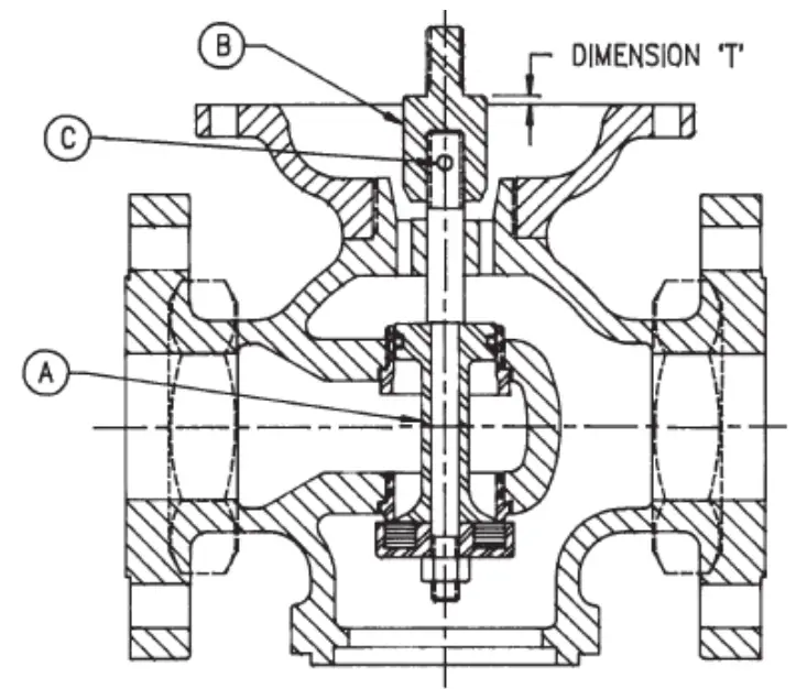
Figure 2. Type D34 Pressure Reducing Valve Setting
Valve Setting (Refer to Figure 2)
If the threaded connection between stem coupling (key 11) and stem (key 14) is disturbed, follow these steps:
- Insert stem assembly (A) and hold disc on seat ring in closed position, as shown in Figure 2.
- Screw stem coupling (B) on stem until travel setting T is reached.
- Remove stem assembly (A) and lock setting by drilling hole and inserting dowel pin (C).
Dismantling
To change or inspect composition disc or sealing ring:
- Remove blind flange (key 24).
- Remove stem nuts (key 22). Keep stem from turning by inserting screw driver in slot on end of stem.
- Disc holder (key 21) drops out. Carefully remove balance piston (key 18) so as not to damage sealing ring (key 16) as it is pulled through seat ring (key 19).
To examine diaphragm or stem:
- Remove compression from spring by turning adjusting screw (key 1) counter-clockwise.
- Remove diaphragm bolts (key 9) and lift off spring chamber (key 4).
- Lift pressure plate (key 7) to withdraw diaphragm and stem from valve.
- To examine diaphragm, disassemble coupling nut (key 6) and lift off pressure plate (key 7).
Troubleshooting
Inadequate flow or delivery pressure:
- Check for clogged control ports connecting body outlet with diaphragm chamber.
- Check for deposits causing sticking of sealing ring (key 16) or stem (key 14) in their respective guides.
Check initial pressure to see if full intended line pressure is applied at the valve inlet.
Reduced pressure builds up:
- Foreign matter may be lodged between disc (key 20) and seat ring (key 19). Remove blind flange (key 24) and inspect it.
- Diaphragm (key 8) may be ruptured. Remove spring chamber (key 4) and inspect it.
- Sealing ring (key 16) may be damaged. See dismantling instructions to replace sealing ring. Parts Ordering
When corresponding with your local Sales Office about this equipment, always reference the equipment valve size, service and serial number.
When ordering replacement parts, reference the key number of each needed part as found in the following parts list and indicate the part number.
Parts List
| Key Description | Part Number |
| Spare Parts Kit (included are keys | |
| 6, 7, 8, 11, 13, 14, 16, 20, 21, 22 and 23) | |
| NPS 1 / DN 25 | WAL33162 |
| NPS 1-1/4 / DN 32 | WAL33163 |
| NPS 1-1/2 / DN 40 | WAL33164 |
| NPS 2 / DN 50 | WAL33165 |
| NPS 2-1/2 / DN 65 | WAL33166 |
| NPS 3 / DN 80 | WAL33167 |
| NPS 4 / DN 100 | WAL33168 |
| NPS 5 / DN 125 | WAL33169 |
| NPS 6 / DN 150 | WAL33170 |
| Type D34 Pressure Reducing Valve | See Table 2 |
Table 2. Type D34 Parts List
| ITEM NO. | PART NAME | MATERIAL | VALVE SIZE. NPS I DN | |||
| 1125 | 1-114 / 32 | 1-112140 | 2150 | |||
| 1 | Adjusting Screw | Steel | WAL05-04880-00 | WAL05-04882-00 | WAL05-04884-00 | WAL05-04885-00 |
| 2 | Adjusting Screw Locknut | Steel | WAL05-02942-00 | WAL05-02942-00 | WAL05-02943-00 | WAL05-02944-00 |
| 3 | Spring Button | Cast Iron | WAL04-01042-00 | WAL04-01042-00 | WAL04-01043-00 | WAL04-01044-00 |
| 4 | Spring Chamber | Cast Iron | WAL04-01410-00 | WAL04-01410-00 | WAL04-01409-01 | WAL04-01412-00 |
| 5 | Ai:gusting Spring. 10-40 psi | Steel | WAL05-05111-01 | WAL05-05111-01 | WAL05-05154-00 | WAL05-05112-01 |
| Ai:gusting Spring. 30-80 psi | Steel | WAL05-05144-00 | WAL05-05144-00 | WAL05-05145-00 | WAL05-05148-00 | |
| Coupling Nut | Steel | WAL05-03018-00 | WAL05-03018-00 | WAL05-03018-00 | WAL05-03018-00 | |
| Pressure Plate | Cast Iron | WAL04-03702-00 | WAL04-03702-00 | WAL04-03703-00 | WAL04-03845-00 | |
| Diaphragm | Hycar | WAL05-01808-00 | WAL05-01808-00 | WAL05-01809-00 | WAL05-011310-00 | |
| 9 | Diaphragm Bolts | Steel | WAL05-04771-00 | WAL05-04771-00 | WAL05-04771-00 | WAL05-04771-00 |
| 10 | Base | Cast Iron | WAL04-00454-01 | WAL04-00454-01 | WAL04-00458-00 | WAL04-00457-00 |
| 11”’ | Stem Coupling | Stainless Steel | WAL04-09484-00 | WAL04-09485-00 | WAL04-11371-00 | WAL04-094813-00 |
| 12 | Diaphragm Nut | Steel | WAL05-02872-00 | WAL05-02872-00 | WAL05-02872-00 | WAL05-02872-00 |
| Ian | Dowel Pin | Steel | WAL05-03884-00 | WAL05-03245-00 | WAL05-03247-00 | WAL05-03251-00 |
| 141′ | Stem | Stainless Steel | WAL04-05333-01 | WAL04-05335-01 | WAL04-05338-01 | WAL04-05339-01 |
| 15 | Body – ANSI NPT Scr | Cast Iron | WAL04-00921-00 | WAL04-00922-00 | WAL04-00923-00 | WAL04-00928-00 |
| Body -ANSI 125 FIg | Cast Iron | – – – – | – – – – | – – – – | WAL04-00914-00 | |
| Body -ANSI 250 FIg | Cast Iron | – – – – | – – – – | – – – – | WALO4-00925-00 | |
| 18*. | Sealing Ring | Hycar | WAL05-04015-00 | WAL05-04019-00 | WAL05-04023-00 | WAL05-04028-00 |
| 17 | Guide Ring | Stainless Steel | WAL04-04397-01 | WAL04-04399-01 | WAL04-04401-01 | WAL04-04403-01 |
| 18 | Balanced Piston | Stainless Steel | WAL04-09478-00 | WAL04-09477-00 | WAL04-09478-00 | WAL04-09479-00 |
| Balanced Piston Assembly | Stainless Steel | – – – – | – – – – | – – – – | —- | |
| 19 | Seat Ring | Stainless Steel | WAL04-04187-02 | WAL04-04189-02 | WAL04-04171-02 | WAL04-04172-02 |
| 20″ | Composition Disk | Nkrie | WAL05-01715-00 | WAL05-01718-00 | WAL05-01718-00 | WAL05-01717-00 |
| 21″‘ | Composition Disk Holder | Stainless Steel | WAL04-09488-00 | WAL04-09489-00 | WAL04-09490-00 | WAL04-09491-00 |
| 220, | Stem Nut | Steel | WAL05-03014-00 | WAL05-03015-00 | WAL05-03018-00 | WAL05-030113-00 |
| 23’0′ | Blind Flange Gasket | Graphite | WAL05-02381-01 | WAL05-02382-01 | WAL05-02382-01 | WAL05-02385-01 |
| 24 | Blind Flange | Cast Iron | WAL04-02171-01 | WAL04-02173-00 | WAL04-02178-00 | WAL04-02178-00 |
| 25 | Blind Flange Nut | Steel | WAL05-02847-00 | WAL05-02851-00 | WAL05-02854-00 | WAL05-02858-00 |
| 28 | Blind Flange Studs | Ledloy | WAL04-05518-00 | WAL04-10118-00 | WAL05-05507-00 | WAL04-05443-00 |
| 27 | Range Tag. 10-40 psi | Aluminum | WAL05-08221-00 | WAL05-08221-00 | WAL05-08221-00 | WAL05-08221-00 |
| Range Tag. 30-80 psi | Aluminum | WAL05-08222-00 | WAL05-08222-00 | WAL05-08222-00 | WAL05-08222-00 | |
* Recommended Spare Part
- These parts furnished in Repair Kit.
For NPS 6 / DN 150, please contact Factory.
Table 2. Type D34 Parts List (continued)
| ITEM NO. | PART NAME | MATERIAL | VALVE SIZE. NPS / DN | |||
| 2-1/2 / 65 | 3180 | 41100 | 61150 | |||
| 1 | Adjusting Screw | Steel | WAL05-04868-00 | WALOS-04807-00 | WAL05-04889-00 | WAL05-04871-00 |
| 2 | Adjusting Screw Lockout | Steel | WAL05-02944-00 | WAL05-02945-00 | WAL05-02948-00 | WAL05-02948-00 |
| 3 | Spring Button | Cast Iron | WAL04-01045-00 | WAL05-01048-00 | WAL05-01047-00 | WAL04-01048-00 |
| 4 | Spring Chamber | Cast Iron | WAL04-01413-00 | WAL04-01414-00 | WAL04-01417-00 | WAL04-01418-00 |
| 5 | Adjusting Spring. 10-40 psi | Steel | WAL05-05114-00 | WAL05-05115-01 | WAL05-05155-00 | WALO5-05156-00 |
| Adjusting Spring. 30-80 psi | Steel | WAL05-05147-00 | WAL05-05148-00 | WAL05-05150-00 | WALO5-05151-00 | |
| 6¹ | Coupling Nut | Steel | WAL05-03019-00 | WAL05-03019-00 | WAL05-03020-00 | WALO5-03020-00 |
| 7¹ | Pressure Plate | Cast Iron | WAL04-03848-00 | WAL04-03847-00 | WAL04-03849-00 | WAL04-03850-00 |
| 8¹ | Diaphragm | Hycar | WAL05-01811-00 | WAL05-01812-00 | WAL05-01814-00 | WAL05-01815-00 |
| 9¹ | Diaphragm Bolts | Steel | WAL05-04778-00 | WAL05-04777-00 | WAL05-04782-00 | WAL05-04783-00 |
| 10 | Base | Cast Iron | WAL04-00458-00 | WAL04-00459-00 | WAL04-00481-00 | WAL04-00482-00 |
| 11¹ | Stem Coupling | Stainless Steel | WAL04-09487-00 | WAL04-09487-00 | WAL04-01498-01 | WAL04-01498-01 |
| 12 | Diaphragm Nut | Steel | WAL05-02875-00 | WAL05-02875-00 | WAL05-02877-00 | WAL05-02877-00 |
| 13,¹ | Dowel Pin | Steel | WAL05-03251-00 | WAL05-03251-00 | WAL05-03254-00 | WALO5-03254-00 |
| 14¹ | Stem | Stainless Steel | WAL04-05341-00 | WAL04-05343-00 | WAL04-05348-00 | WAL04-08879-00 |
| 15 | Body – ANSI NPT Scr | Cast Iron | – – – – | – – – – | – – – – | – – – – |
| Body -ANSI 125 Fig | Cast Iron | WAL04-00915-00 | WAL04-00918-00 | WAL04-00920-00 | WAL04-00913-00 | |
| Body -ANSI 250 Fig | Cast Iron | WAL04-00927-00 | WAL04-00928-01 | WAL04-00930-00 | WAL04-00931-00 | |
| 16¹ | Sealing Ring | Hycar | WAL05-04033-00 | WAL05-04038-00 | WAL05-04045-00 | WALO5-04050-00 |
| 17 | Guide Ring | Stainless Steel | WAL04-04405-00 | WAL04-04407-00 | WAL04-04411-01 | WAL04-08880-00 |
| 18 | Balanced Piston | Stainless Steel | WAL04-09480-00 | WAL04-09481-00 | – – – – | – – – – |
| Balanced Piston Assembly | Stainless Steel | – – – – | – – – – | WAL22445 | WAL22525 | |
| 19 | Seat Ring | Stainless Steel | WAL04-04175-01 | WAL04-04177-01 | WAL04-04180-02 | WAL04-08881-01 |
| 20¹, | Composition Disk | Nkrie | WAL05-01718-00 | WAL05-01719-00 | WAL05-01721-00 | WAL05-01722-00 |
| 21¹ | Composition Disk Holder | Stainless Steel | WAL04-09492-00 | WAL04-09493-00 | WAL04-09494-00 | WAL04-02531-00 |
| 22¹ | Stem Nut | Steel | WAL05-03017-00 | WAL05-03017-00 | WAL05-03018-00 | WAL05-03019-00 |
| 23¹ | Blind Flange Gasket | Graphite | WAL05-02388-01 | WAL05-02387-01 | WAL04-02389-01 | WALO5-02371-00 |
| 24 | Blind Flange | Cast Iron | WAL04-02180-00 | WAL04-02183-00 | WAL04-02188-00 | WAL04-02159-00 |
| 25 | Blind Flange Nut | Steel | WAL05-02880-00 | WAL05-02882-00 | WAL05-02880-00 | WALO5-02882-00 |
| 28 | Blind Flange Studs | Ledloy | WAL04-10119-00 | WAL04-05448-00 | WAL04-10119-00 | WAL04-05448-00 |
| 27 | Range Tag. 10-40 psi | Aluminum | WAL05-06221-00 | WAL05-08221-00 | WAL05-08221-00 | WAL05-08221-00 |
| Range Tag. 30-80 psi | Aluminum | WAL05-06222-00 | WAL05-08222-00 | WAL05-08222-00 | WALO5-06222-00 | |
* Recommended Spare Part
1. These parts furnished in Repair Kit.
For NPS 6 / DN 150, please contact Factory.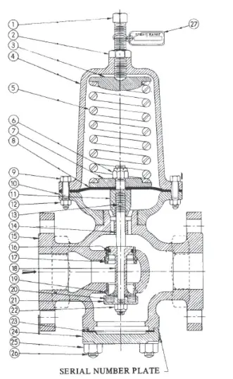
Figure 3. Type D34 Pressure Reducing Valve Assembly Drawing
SpenceValve.com
Emerson Automation Solutions
| Americas McKinney, Texas 75070 USA T +1 800 558 5853 +1 972 548 3574 | Asia Pacific Singapore 128461, Singapore T +65 6777 8211 |
| Europe Bologna 40013, Italy T +39 051 419 0611 | Middle East and Africa Dubai, United Arab Emirates T +971 4 811 8100 |
VCIMD-14932 © 2021 Emerson Electric Co. All rights reserved 11/21. Spence is a mark owned by one of the companies in the Emerson Automation Solutions business unit of Emerson Electric Co. The Emerson logo is a trademark and service mark of Emerson Electric Co. All other marks are property of their prospective owners.
The contents of this publication are presented for informational purposes only, and while every effort has been made to ensure their accuracy, they are not to be construed as warranties or guarantees, express or implied, regarding the products or services described herein or their use or applicability. All sales are governed by our terms and conditions, which are available upon request. We reserve the right to modify or improve the designs or specifications of such products at any time without notice.
Emerson Electric Co. does not assume responsibility for the selection, use or maintenance of any product. Responsibility for proper selection, use and maintenance of any Emerson Electric Co. product remains solely with the purchaser.
![]() SD1103A
SD1103A


