GIRA 5061 00 Switching Actuator Instruction Manual
Safety instructions
 | Electrical devices may only be mounted and connected by electrically skilled persons. |
Serious injuries, fire or property damage possible.
Please read and follow manual fully.
Danger of electric shock.
Device is not suitable for disconnection from supply voltage.
Danger of electric shock.
Make sure during the installation that there is always sufficient insulation between the mains voltage and the bus.
A minimum distance of at least 4 mm must be maintained between bus conductors and mains voltage cores.
Danger of electric shock on the KNX installation.
Do not connect any external voltage to the inputs.
The device might be damaged, and the SELV potential on the KNX bus line will no longer be available.
This manual is an integral part of the product, and must remain with the end customer.
Device components
- Programming LED
- Programming button
- Control cable (KNX connection and extension inputs)
- Load connection (relay output)
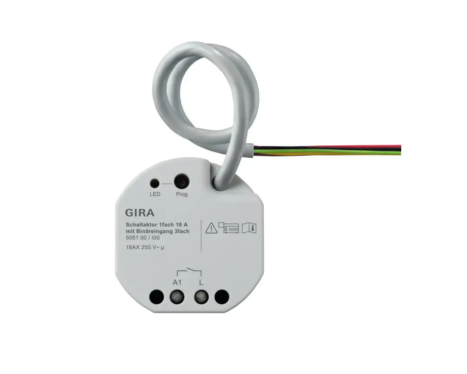
Image 1: Device components
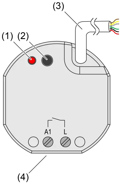
Image 2: Connection assignment of control cable (example)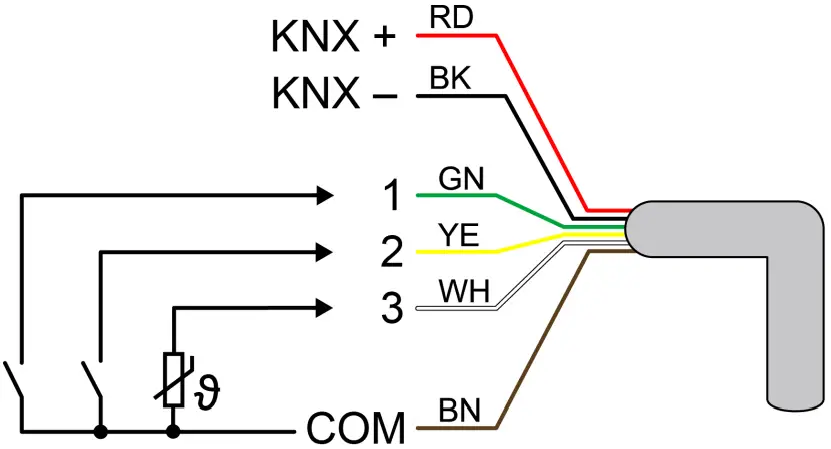
- Red (RD): KNX +
- Black (BK): KNX –
- Green (GN): Input 1 (push-button, switch, contact, condensation/leakage sensor)
- Yellow (YE): Input 2 (push-button, switch, contact, condensation/leakage sensor)
- White (WH): Input 3 (push-button, switch, contact, condensation/leakage sensor, NTC temperature sensor)
- Brown (BN): COM inputs 1…3
Function
System information
This device is a product of the KNX system and complies with the KNX directives.
Detailed technical knowledge obtained in KNX training courses is a prerequisite to proper understanding.
The function of this device depends upon the software.
Detailed information on loadable software and attainable functionality as well as the software itself can be obtained from the manufacturer´s product database.
The device can be updated. Firmware can be easily updated with the Gira ETS Service App (additional software).
The device is KNX Data Secure capable. KNX Data Secure offers protection against manipulation in building automation and can be configured in the ETS project.
Detailed specialist knowledge is required. A device certificate, which is attached to the device, is required for safe commissioning.
During mounting, the device certificate must be removed from the device and stored securely.
Planning, installation and commissioning of the device are carried out with the aid of the ETS, version 5.7.3 and above.
Intended use
- Operating in KNX systems
- Switching of electrical consumers via relay contact
- Reading in switching states of installation switches or push-buttons and other potential-free contacts at inputs 1…3
- Signal evaluation of condensation and leakage sensors at inputs 1…3 (see accessory).
- Acquisition of temperature values via NTC temperature sensor at input 3 (see accessories)
- Mounting in appliance boxes according to DIN 49073
Product characteristics
- Output can be operated via KNX telegrams or extension inputs
- Three extension inputs for connecting potential-free contacts or dew/leakage sensors.
NTC temperature sensor can be connected to input 3. - Supply via KNX, no additional power supply necessary
- KNX Data Secure compatible
- Updatable with Gira ETS Service App
Characteristics switch operation
- Operation as NO or NC contacts
- Feedback function
- Logic and restraint function
- Central switching functions
- Time functions: switch-on delay, switch-off delay, staircase lighting timer with run-on time
- Scene function
- Operating hours counter
Extension input characteristics
- Switching operating function
- Dimming operating function (incl. colour temperature dimming)
- Shutter/Venetian blinds operating function
- Value transmitter operating function (1-byte, 2-byte, 3-byte and 6-byte incl. RGBW and colour temperature presets)
- Scene extension operating function
- 2-channel operation operating function
- Controller extension operating function
- Disabling functions
- De bounce time adjustable
Logic function characteristics
- Logic gate
- Transformer (conversion)
- Disabling element
- Comparator
- Limit value switch
Information for electrically skilled persons
![]() DANGER!
DANGER!
Mortal danger of electric shock.
Disconnect the device. Cover up live parts.
Mounting and electrical connection
![]() DANGER!
DANGER!
When connecting the bus/extensions and mains voltage wires in a shared appliance box, the KNX bus line may come into contact with the mains voltage.
This endangers the safety of the entire KNX installation.
People at remote devices may also receive an electric shock.
Do not place bus/extensions and mains voltage terminals in a shared connection compartment.
Use an appliance box with a fixed partition wall or separate appliance boxes.
Connecting and fitting the device
In secure operation (preconditions):
- Secure commissioning is activated in the ETS.
- Device certificate entered/scanned or added to the ETS project.
A high resolution camera should be used to scan the QR code. - Document all passwords and keep them safe.
Mounting in suitable appliance box (recommendation: electronic device box with partition).
Observe cable routing and spacing (see figure 3)
Image 3: Mounting example in electronic appliance box with partition wall, series push-button and NTC temperature sensor
- (5) Appliance box
- (6) Partition
- (7) potential-free contacts (e.g. series push-button)
- (8) NTC temperature sensor (optional)
Image 4: Cable spacing
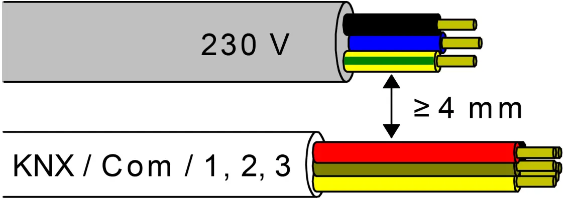
Minimum spacing between the mains voltage and bus/extension wires: 4 mm (see figure 4)
Image 5: Connection of load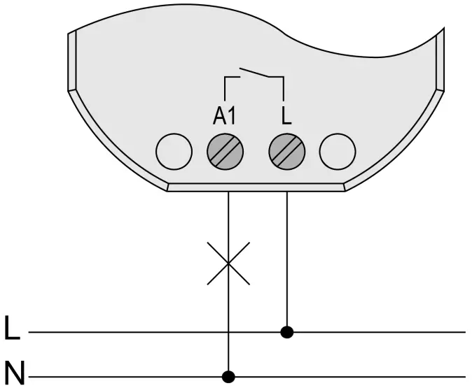
Observe ambient temperature. Ensure adequate cooling.
- Connect the device to KNX with the correct polarity.
- Connect load as shown in the connection example (see figure 5).
- If required, connect potential-free contacts or condensation/leakage sensors to inputs 1…3, or NTC temperature sensors to input 3 (see figure 2).
- Install the device in the appliance box.
- In secure operation: The device certificate must be removed from the device and stored securely.
![]() The COM reference potential must not be connected together with COM connections of other devices!
The COM reference potential must not be connected together with COM connections of other devices!
Commissioning
Commissioning the device
![]() NOTICE!
NOTICE!
Undefined relay state at delivery.
Unexpected control of connected loads.
During commissioning, before switching on the load, ensure that all relay contacts are open by applying the KNX bus voltage.
Observe commissioning sequence!
- Switch on the KNX bus voltage.
- Wait about 10 s.
- Connect the load circuit.
![]() Delivery state: Operation of the output via switch at input 1 (ON / OFF) possible. Inputs 2 and 3 have no function
Delivery state: Operation of the output via switch at input 1 (ON / OFF) possible. Inputs 2 and 3 have no function
Function of Inputs in the as-delivered state
Load physical address and application program
- Press the programming button.
The programming LED lights up. - Load physical address and application program using the ETS.
Safe-state mode
The safe-state mode stops the execution of the loaded application program.![]() Only the system software of the device is still functional. ETS diagnosis functions and programming of the device are possible.
Only the system software of the device is still functional. ETS diagnosis functions and programming of the device are possible.
Activating safe-state mode
- Switch off the bus voltage or disconnect the device from the KNX.
- Wait about 10 s.
- Press and hold down the programming button.
- Switch on the bus voltage or connect the device to KNX. Release the programming button only after the programming LED starts flashing slowly.
The safe-state mode is activated.
By briefly pressing the programming button again, the programming mode can also be switched on and off in the safe-state mode as usual.
If the programming mode is active, the programming LED stops flashing.
Deactivating safe-state mode
- Switch off bus voltage (wait approx. 10 s) or carry out ETS programming.
Master reset
The master reset restores the basic device settings (physical address 15.15.255, firmware remains in place).
The device must then be recommissioned with the ETS.
In secure operation: A master reset deactivates device security.
The device can then be recommissioned with the device certificate.
Performing a master reset
Precondition: The safe-state mode is activated.
- Press and hold down the programming button for > 5 s.
The programming LED flashes quickly.
The device performs a master reset, restarts and is ready for operation again after approx. 5 s.
Restoring the device to factory settings
Devices can be reset to factory settings with the Gira ETS Service App.
This function uses the firmware contained in the device that was active at the time of delivery (delivered state).
Restoring the factory settings causes the devices to lose their physical address and configuration.
Technical data
| KNX | |
| KNX medium | TP256 |
| Commissioning mode | S-mode |
| Rated voltage KNX | DC 21 … 32 V SELV |
| Current consumption KNX | 5 … 18 mA |
| Connection mode KNX | Device connection terminal on control cable |
| Outputs | |
| Connection mode | Screw terminals |
| Switching voltage | AC 250 V ~ |
| Switching current | 16 AX |
| Switch-on current 200 μs | max. 800 A |
| Switch-on current 20 ms | max. 165 A |
| Connected load | |
| Ohmic load | 2500 W |
| Capacitive load | max. 16 A (140 μF) |
| Motors | 1380 VA |
| Incandescent lamps | 2300 W |
| HV halogen lamps | 2300 W |
| HV-LED lamps | max. 400 W |
| LV halogen lamps with electronic transformers | 1500 W |
| LV halogen lamps with inductive transformer | 1000 W |
| Compact fluorescent lamps uncompensated | 1160 W (140 μF) |
| Reduction of connected load | |
| per 5 °C in excess of 35 °C | -10% |
| when installed in wooden or dry construction wall | -15% |
| when installed in multiple combinations | 20% |
| Clampable conductor cross-section | |
| Single stranded | 0.5 … 4 mm² |
| Finely stranded without conductor sleeve | 0.5 … 4 mm² |
| Finely stranded with conductor sleeve | 0.5 … 2.5 mm² |
| Connection torque, screw terminals | max. 0.8 Nm |
| Ambient conditions | |
| Ambient temperature | -5 … +45 °C |
| Storage/transport temperature | 25 … +70 °C |
| Dimensions (W × H × D) | 48 x 50 x 28 mm |
| Inputs | |
| Control cable (pregerminated) | YY6x0.6 |
| Input type | Potential-free |
| Number | 3 |
| Total length of extension device cable | max. 10 m |
| Cable type (preferably) | J-Y(St)Y |
| Poll voltage, extension inputs | approx. 5 V |
Accessories
- Remote sensor (NTC temperature sensor): 1493 00
- Condensation sensor: 5069 00
- Leakage sensor: 5068 00
Warranty
The warranty is provided in accordance with statutory requirements via the specialist trade.
Please submit or send faulty devices postage paid together with an error description to your responsible salesperson (specialist trade/installation company/electrical specialist trade).
They will forward the devices to the Gira Service Center.
CUSTOMER SUPPORT
Deutschland
Tel: +49(0)21 95 – 602-0
Fax: +49(0)21 95 – 602-191
Web: www.gira.de
Email: [email protected]


