![]() Installation instructions
Installation instructions
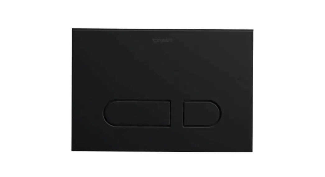
Actuator Plate
# WD5008 011 090
# WD5008 021 090
# WD5008 031 090
70300133_Mounting_Actuator_Plate_A1![]() Important information
Important information![]() Installation
Installation
About these instructions
The installation instructions come as part of the Duravit product and must be read carefully prior to installation.
Target readership and qualifications
This is a professional-grade product. Working knowledge of construction techniques and code-compliant plumbing installation is required for proper installation and user
satisfaction. The product must be installed by a licensed plumber.
Explanation of the keywords and symbols
 | Inspection (e.g. for scratches) |
 | Inspect for leaks and that all connections have a watertight seal |
 | Indication of the length of time (e.g. 10 minutes) |
Action required
Safety instructions
Product and/or property damage
The breach of local and country-specific regulations and standards can cause damage to the product and/or property damage.
> Observe the local installation regulations and any country-specific standards at all times.
Prior to installation
Please read the specification sheets prior to the installation.
Specification sheets are available for download at www.pro.duravit.us. Products are in compliance with the latest editions of:
- Uniform Plumbing Code (UPC ® )
- National Plumbing Code of Canada
- ASME: A112.6.2, A112.19.5, A112.1002, A112.18.6
- ANSI Z124.4
- CSA: B125.12, B125.6
- ANSI/ASSE 1002
- IAPMO PS-50
- ULNAR / ULNAR-HET
- the State of Massachusetts listed
- This concealed tank is WaterSense ® listed or compliant when used in combination with listed Duravit toilet bowls.
 http://duravit.us/wallmountedtoilets
Warranty: Find our General Terms and Conditions (GTC) at www.pro.duravit.us/gtc.

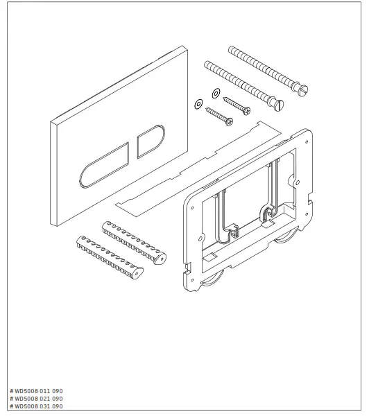
 Delivery contents
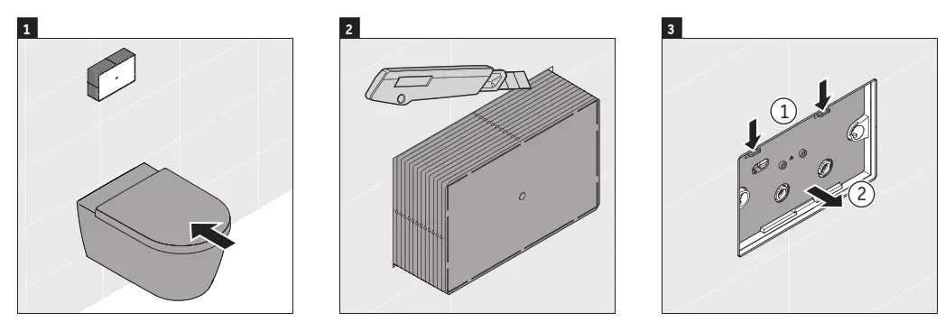 | ||
| > Complete installation of the wall-mounted toilet bowl. | > Remove the actuator protective cover using a box cutter along the perforated edge that is flush to the finished wall. | > Press the cover release buttons at the top inserts to remove the actuator cover and expose the inner mechanism. |
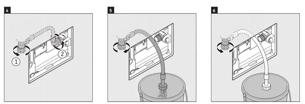 | ||
| > Close angle stop. > Disconnect the supply line from the fill valve. | > Run the supply hose to a bucket. > Turn on angle stop to flush the outline of debris. | > Turn the angle stop off once the line is sufficiently flushed. |
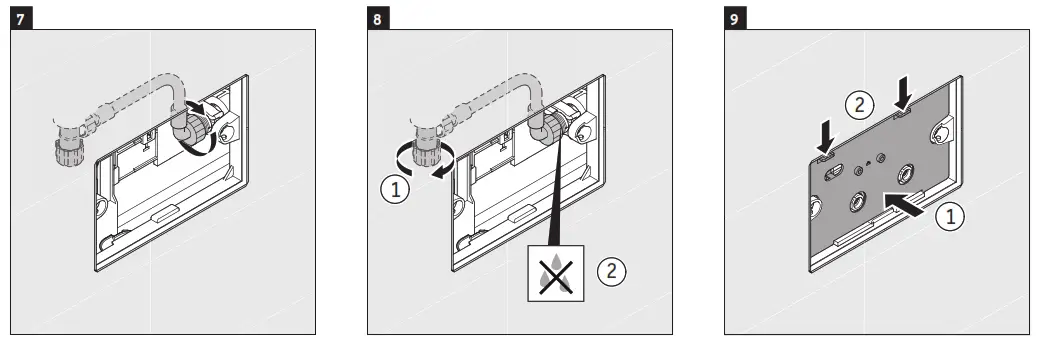 | ||
| > Reconnect the supply line to fill the valve. | > Turn on the supply line. > Ensure no leaks are present. | > Reinstall the actuator inner cover plate. |
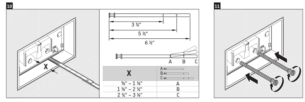 | ||
| > Measure the depth of the finished wall to the inner cover plate. | > Cut the flush rods to the appropriate length at perforation using the X measurement > Refer to the above chart. | > Install flush rods. |
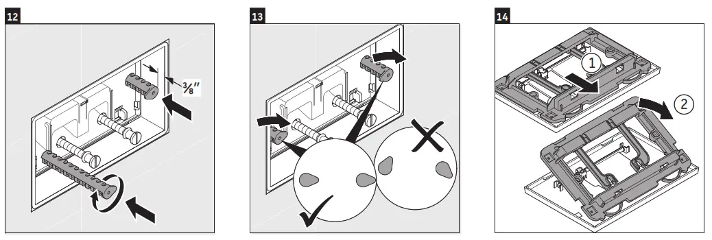 | ||
| > Install plate locking rod set at a depth of ⅜” from the finished wall. | > Set rod endpoints as to the above diagram. > Check to ensure there are no leaks. | > Remove plate mounting from the back of the actuator plate. |
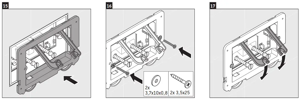 | ||
| > Position mounting frame onto actuator. | > Secure mounting frame to the wall using provided screws and washers. | > Position actuator hinges over rods to secure in place. |
DURAVIT USA, INC.
2635 North Berkeley Lake Rd., Ste. 100
Duluth, GA 30096 Toll-Free 888-DURAVIT
Phone 770-931-3575
Fax 770-931-8454
[email protected]
www.duravit.us
Order no. (manual): 70300133/21.04.1
Reference no. (manual): 57459/21.04.1 We reserve the right to make technical improvements and design modifications to the products illustrated.


