![]()
5301 00 eNet Server
Instruction Manual
5301 00 eNet Server
 Safety instructions
 Safety instructions
![]() Electrical devices may only be mounted and connected by electrically skilled persons.
Electrical devices may only be mounted and connected by electrically skilled persons.
Serious injuries, fire, or property damage are possible. Please read and follow the manual fully.
Fire hazard! Operation exclusively with the power supplies listed under accessories The radio communication takes place via a non-exclusively available transmission path and is therefore not suitable for safety-related applications, such as emergency stops and emergency calls.
This manual is an integral part of the product and must remain with the end customer.
Device components
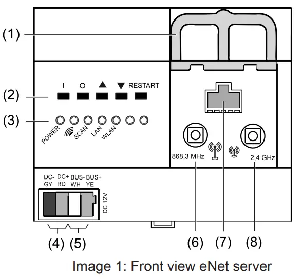
- Slide for retaining the antenna cable
- Buttons for manual operation and restart
- LEDs
- Voltage supply connection
- Data cable connection
- Socket for external eNet antenna
- RJ45 socket for Ethernet connection
- Socket for external WLAN antenna
Function
Intended use
- Commissioning, diagnosis, and maintenance of an eNet installation via PC, tablet, and laptop
- Operation of an eNet installation via smartphone
- Radio receiver for eNet RMD modules
- Operation only with approved voltage supply (see accessories)
- Mounting on DIN rail according to EN 60715 in distribution boxes with voltage supply RMD
Product characteristics
- Internal eNet radio and WLAN antenna
- External eNet radio and WLAN antennas for extending the radio ranges can additionally, be connected
- LEDs for signaling
- Buttons for construction site mode and restart of the eNet server
- The electrical separation between the connections of the external antennas and the Ethernet connection
- Fully-encrypted radio transmission (AES-CCM) from eNet Server software version
2.0 Signalling
The table below provides an overview of the signalling via LEDs of the eNet server.
| Labelling, Colour of the LED | Function |
| POWER, green | Flashes: eNet-Server starts Illuminated: eNet server ready for operation |
| eNet radio transmission active | |
| SCAN, green | Scan operating mode active |
| LAN, green | Ethernet connection active |
| WLAN, green | WLAN connection active |
Operation
Operation on the device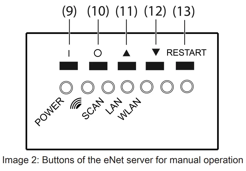
(9)The button I: All On
(10)Button O: All Off
(11)Button ![]() : All Up
: All Up
(12)Button ![]() All Down
All Down
(13)Button RESTART
Switching all switches and dimmers
- Press the I button to switch it on.
- Press the O button to switch it off.
Moving all blinds/shutters
- Press
 the button to raise the blinds/shutters.
 - Press
 button to lower the blinds/shutters.
Performing a restart
The eNet server can be restarted without voltage interruption via the RESTART button.
- Press the RESTART button (13) for longer than 10 seconds. A restart of the eNet server is performed. The POWER LED flashes during the restart and illuminates when the eNet server is ready for operation. Resetting network configuration
- Press the RESTART button (13) for longer than 4 seconds. The POWER,
 and SCAN LEDs flash.
 - To reset the network configuration to LAN with the fixed IP address (192.168.0.22), press button within 10 seconds.
- To reset the network configuration to LAN with DHCP-Modus, press button within 10 seconds.
The network configuration is reset and WLAN is deactivated.
Resetting users and passwords to factory setting
- Press the RESTART button (13) for longer than 4 seconds. The POWER, and SCAN LEDs flash.
- Within 10 seconds press the I button for 4 seconds. Users and passwords are reset to the factory settings. A restart of the eNet server is performed. The POWER LED flashes during the restart and illuminates when the eNet server is ready for operation.
![]() For the first log-on, enter “admin” both as the username and password. For security reasons, change the password after this.
For the first log-on, enter “admin” both as the username and password. For security reasons, change the password after this.
Delete project
- Press the RESTART button (13) for longer than 4 seconds. The POWER, and SCAN LEDs flash.
- Within 10 seconds press the O button for 4 seconds. The project is deleted. A restart of the eNet server is performed. The POWER LED flashes during the restart and illuminates when the eNet server is ready for operation.
Information for electrically skilled persons
5.1 Mounting and electrical connection![]() DANGER!
DANGER!
The electrical shock on contact with live parts in the installation environment. Electric shocks can be fatal.
Before working on the device, disconnect the power supply and cover up live parts in the working environment.
Connecting external antennas
An external WLAN antenna can be connected to improve the radio range of the WLAN connection. An eNet antenna can be connected to improve the radio range between the eNet server and installation devices.
- Unlock slide (1) by pulling the end of the bow forwards. Pull out the slide.
- Place the antenna outside of the distribution board and insert the antenna cable into the distribution board.
![]() The eNet antenna must be mounted on a metallic surface.
The eNet antenna must be mounted on a metallic surface.![]() The antenna cables carry SELV potential and are only singly insulated. Ensure safe isolation from other voltages, e.g. through insulation.
The antenna cables carry SELV potential and are only singly insulated. Ensure safe isolation from other voltages, e.g. through insulation.
- Insert the antenna connector into the socket (6) for the eNet antenna or socket (8) for the WiFi antenna.
- Re-insert slide (1) until it engages noticeably.
![]() The slide fixes the antenna cable in place and ensures that the maximum installation height in the distribution board is maintained.
The slide fixes the antenna cable in place and ensures that the maximum installation height in the distribution board is maintained.
Mounting the device
Observe the temperature range. Ensure adequate cooling.
- Mount the device on the DIN rail with the terminals facing downwards. facing downwards. Connecting the device
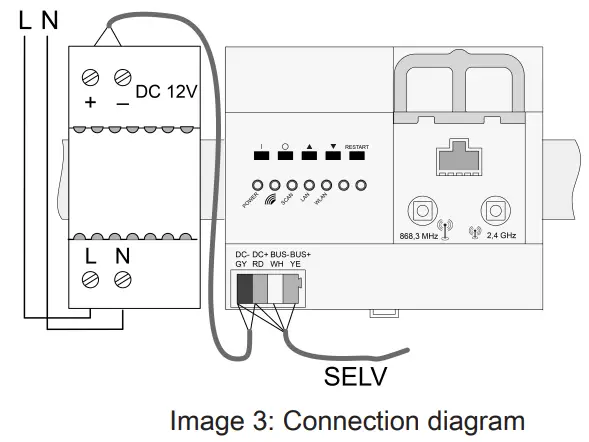
Use a suitable bus line, e.g. J-Y(St)Y 2x2x0.8.
- Connect the device according to the connection diagram (see figure 3).
![]() Unfavourable installation conditions make radio reception more difficult. In the case of metallic sub-divisions etc., connect the external antenna and position it on a metallic surface outside of the distribution board.
Unfavourable installation conditions make radio reception more difficult. In the case of metallic sub-divisions etc., connect the external antenna and position it on a metallic surface outside of the distribution board.![]() Do not connect the eNet server to an RMD radio receiver.
Do not connect the eNet server to an RMD radio receiver.
Connection assignment
| Labeling / Colour | Connection |
| DC–, GY / dark grey | Voltage supply, – |
| DC+, RD / red | Voltage supply, + |
| BUS–, WH / white | Data cable, – |
| BUS+, YE / yellow | Data cable, + |
Connect the voltage supply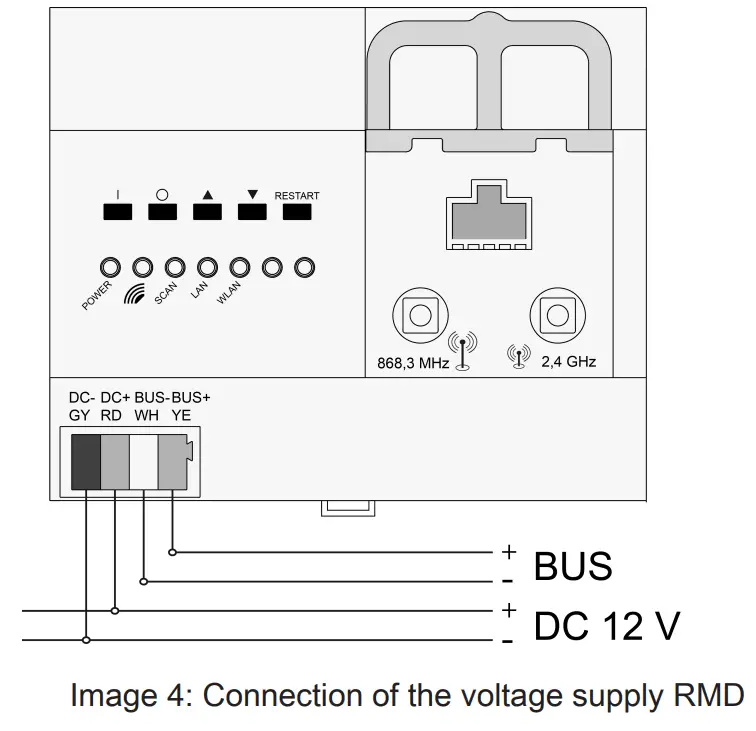
- Connect the voltage supply to connection (4) of the eNet server.
- Switch on the voltage.
The eNet server is started.
5.2 Commissioning
Connecting computer with eNet server
A wired network connection (LAN) via a router is required for the first commissioning of the eNet Server. Addressing takes place automatically via DHCP. In the as-delivered state, the eNet Server is appropriately preconfigured.![]() Supported web browsers: Google Chrome, Firefox, EDGE
Supported web browsers: Google Chrome, Firefox, EDGE
Precondition: The eNet Server is installed, and the voltage supply and any external antennas are connected.
Connection via IP address of the eNet Server
Precondition: The eNet SMART HOME app is installed on a smartphone. The smartphone is connected to a WiFi router.![]() The IP address of the eNet server can be found on the Home page and in the System menu of the app.
The IP address of the eNet server can be found on the Home page and in the System menu of the app.
- Set up the network connection between the eNet Server and the computer via the Wifi router.
- Start a web browser.
- Enter the IP address of the eNet Server in the address line of the web browser.
The log-in window of the commissioning interface is opened in the web browser.
Connection via the domain name of the eNet Server
- Set up the network connection between the eNet Server and the computer via a WiFi router.
- Start web browser.
- Enter the XenServer in the address line of the web browser.
![]() With some routers, the hostname of the router must also be entered, e.g. XenServer.fritz.box. The log-in window of the commissioning interface is opened in the web browser.
With some routers, the hostname of the router must also be entered, e.g. XenServer.fritz.box. The log-in window of the commissioning interface is opened in the web browser.
Log into the commissioning interface
- Enter your username and password.
![]() For the first log-on, enter “admin” both as the username and password. For security reasons, change the password after this.
For the first log-on, enter “admin” both as the username and password. For security reasons, change the password after this.
- Select Anmelden.
![]() For trouble-free data transmission, a wired connection via LAN is recommended.
For trouble-free data transmission, a wired connection via LAN is recommended.
Legal Notice
This product incorporates open-source software components covered by the terms of third-party copyright notices and/or license agreements. The technical documentation of the eNet server contains detailed information on this.
Technical data
| Rated voltage | DC 12 V SELV |
| Current consumption | 400 mA |
| Power consumption | |
| Operation | max. 6 W |
| Standby | max. 2 W |
| Ambient temperature | -5 … +45 °C |
| Storage/transport temperature | -20 … +70 °C |
| Relative humidity | 20 … 70 % (no moisture condensation) |
| Protection class | III |
| Installation width | 108 mm / 6 HP |
| Connections | |
| Supply | device connection terminal |
| LAN | RJ45-socket 8/4-pin |
| WLAN antenna, external | SMB socket |
| Bus line | |
| Cable length | max. 3 m |
| RMD channels | |
| Number | max. 32 |
| IP communication | |
| LAN | Ethernet 10/100 MBit |
| IP connections | max. 8 |
| WLAN (IEEE 802.11g) | |
| Radiofrequency | 2.400 … 2.483 GHz |
| Transmission capacity | max. 100 mW |
| eNet communication | |
| Radiofrequency | 868.0 … 868.6 MHz |
| Transmission capacity | max. 20 mW |
| Transmitting range in free field | typ. 100 m |
| Receiver category | 2 |
Accessories
| Power supply 12 V DC / 2 A DRA | Order no. 5319 00 |
| Additional radio antenna | Order no. 5307 00 |
| Additional WLAN antenna | Order no. 5308 00 |
Conformity
Hereby Gira Giersiepen GmbH & Co. KG declares that the radio system type Order no. 5301 00
corresponds to the directive 2014/53/EU. You can find the full article number on the device. The complete text of the EU Declaration of Conformity is available under the
Internet address: www.gira.de/konformitaet
Warranty
The warranty is provided in accordance with statutory requirements via the specialist trade. Please submit or send faulty devices postage paid together with an error description to your responsible salesperson (specialist trade/installation company/electrical specialist trade). They will forward the devices to the Gira Service Center.
Additional information
You can find a Quick Start Guide as an introduction to working with the eNet Server, product documentation for working with the eNet SMART HOME connect and additional information on the eNet system at www.gira.de
.![]()
Gira
Giersiepen GmbH & Co. KG
Elektro-InstallationsSysteme
Industriegebiet Mermbach
Dahlienstraße
42477 Radevormwald
Postfach 12 20
42461 Radevormwald
Deutschland
Tel +49(0)21 95 – 602-0
Fax +49(0)21 95 – 602-191
www.gira.de
[email protected]
32580562
10869904
29.09.2022


