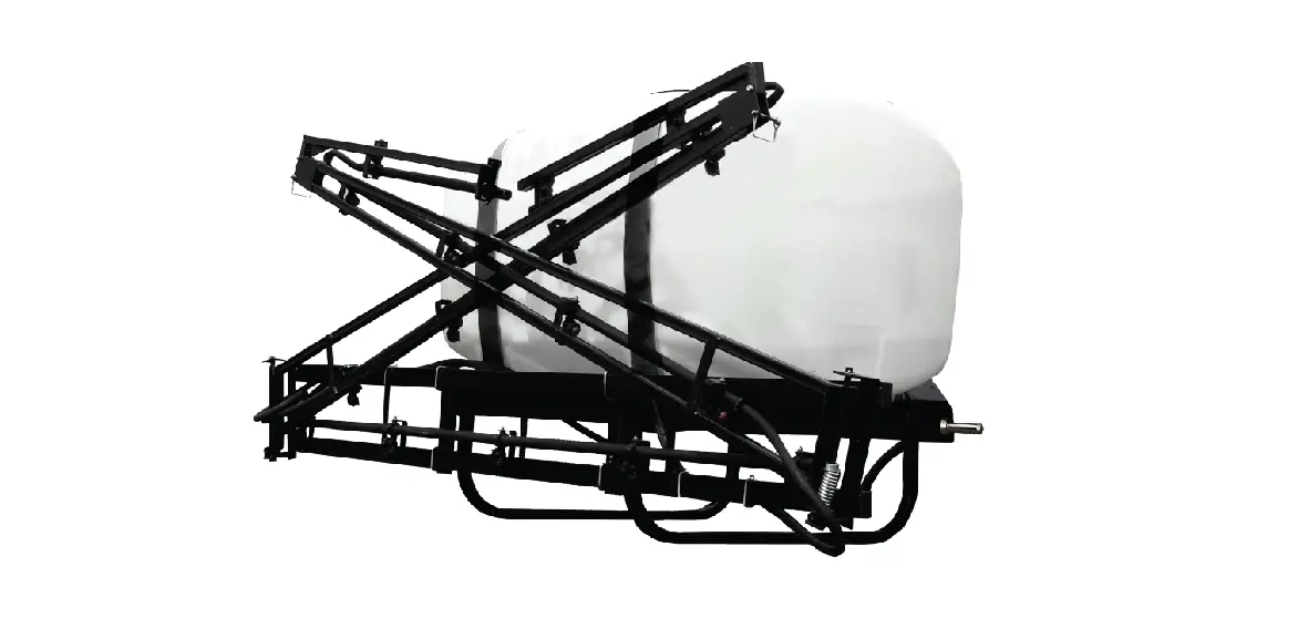
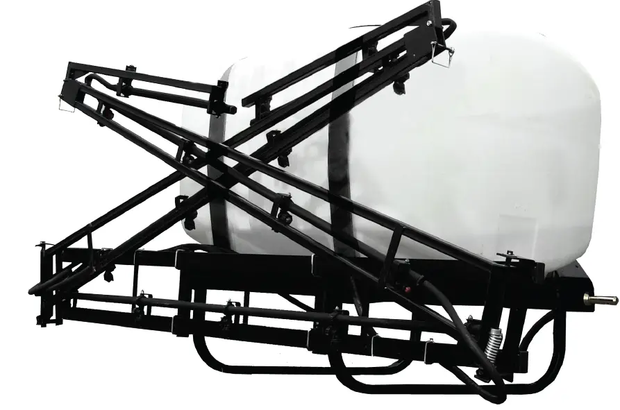
BE-RMS150-28FB 3pt Hitch Sprayer
ASSEMBLY
Sprayer assembly has been completed by at the factory except for the roller pump that must be supplied by the customer. This unit is designed to work with a 4 or 6 roller pump that will be attached directly to the tractor PTO. Depending on pump choice the spray nozzles may need to be changed to deliver optimum spray coverage. Please refer to the “Boom Operation” section for more information.
Two nylon hose fittings and hose clamps have been provided to join to the pump. Use a good quality thread sealant on each fitting to prevent leaks. After the fittings have been inserted to the pump, push on the two pump hoses to the fittings and secure with clamps provided.
OPERATION
Check the inside of the tank for any foreign objects or material that could cause damage to the pump.
Fill the tank with clean water. IT is always better to have the tank at least half full of water before adding the chemical to avoid possible damage to the sprayer components by an undiluted chemical concentrate.
Before initially running the sprayer, loosen the tee handle of the relief valve. This adjustment should be checked while spraying because a pressure increase will be noted when the sprayer is shut off and the output of the pump is by-passed back to the tank through the relief valve.
Limit the pressure to 150 PSI. If, when adjusting the relief valve for more pressure, no increase in pressure occurs, it is an indication that the maximum output of the pump is being used. When the sprayer is shut off the pump will have to overcome the excessive tightness of the relief valve in order to by-pass back to the tank. This will cause pump strain and possible damage and should be avoided.
Choose an operating pressure that provides a spray pattern suitable for the particular operation. Follow the chemical manufacturer’s recommendations for mixing and rates or application carefully. Judge the area sprayed with tank full of spray material carefully to avoid over or under application rates.
Do not use your sprayer for pumping petroleum products, strong acids, paint or other thick materials with heavy viscosity.
GENERAL SPRAYER MAINTENANCE
Most spray materials are highly corrosive. The most important aspect of a long dependable service from the sprayer is a thorough cleaning immediately following each use. In addition, the residue of one type of chemical could cause an undesirable effect when a different chemical is used for a different purpose.
The most effective cleaning method is to pump several rinses of clean water through the tank, pump,
hose and spray gun. A neutralizing agent such a solution of Nutra Sol, detergent or household ammonia as recommended by the chemical manufacturer can assist in removal of persistent chemical.
Avoid getting chemical on the engine and other external parts of the unit in order to preserve the finish. Remove external spray material deposits when cleaning and flushing unit. A coat of wax applied to the exterior will protect the paint and make clean up easier. When the unit is thoroughly cleaned, remove the tank filter bowl and drain the water form the tank, spray gun, pump boom and spray gun hose.
TROUBLESHOOTING
In the event of inefficient operation or malfunction, check the following:
- Clean the line strainer after each use or more often, if necessary. A plugged strainer will restrict the flow of liquid to the pump and cause it to perform poorly. Always use clean water and keep the strainer screen in place. Sandy or gritty liquids will damage the components of the pump.
- Check the hoses for any kinks or leaks. Be sure that the suction hose is not collapsed or plugged.
- Nozzle tips should be removed and cleaned with a toothpick or similar object. Avoid nails, wires, etc. that could damage the top opening. The nozzle screens of the boom accessory should also be removed and cleaned periodically. Inspect and replace worn tips to insure satisfactory spraying performance.
STORAGE
This sprayer should always be cleaned and drained before storage. If the unit will be subjected to freezing temperatures, it is imperative that the whole sprayer; pump, hoses, spray gun, gauge, etc., be completely drained and dry. Any water left in the system could cause extensive damage when it freezes.
Follow the recommendations of the pump instructions for preventing internal pump corrosion and protection against the rotor and rollers gumming and sticking during storage.
BOOM OPERATION
Note: Refer to boom manual for specific information regarding boom set up and operation.
The following is for general information only.
The spray nozzles used in the boom are marked with the capacity in gallon per minute of water at a pressure of 40 PSI. A 3 tip has a capacity of 0.3 GPM at 40 PSI. A 5 has a capacity of 0.5 GPM at 40 PSI. etc.
The spray width coverage of the nozzle will vary according to the pressure, and nozzle height. The wide angle flat spray pattern increases as the pressure is increased.
The amount of material applied by the nozzle is changed by variations in spraying speed, different capacity nozzles, different nozzle spray width and spraying pressures. Other factors such as a heavier or lighter (specific gravity) spraying solution, a change in the chemical-water concentration ratio, worn tip, a worn pump, wheel slippage, a pressure drop from the gauge to the boom, and a pressure gauge variation or malfunction can also cause variations in the rate of application. Uneven coverage can result from a clogged nozzle and a straining screen.
The spraying pressure is usually more in relation to the type of application and the type of tip used than to the rate of application. Since nozzle flow rate is almost proportional to the square root of pressure, it would take four times the amount of range from 10 to 40 PSI. The rate of application can be changed somewhat by changing pressure but a considerable change is achieved by using a different capacity nozzle or (if possible) by changing the spraying ground speed.
Dividing the spraying width of the boom in feet into 1000 determines the travel distance required to cover 1000 sq. feet. For example, an 80” spray width will cover 1000 sq. feet in 150 feet of travel. Periodic calibration checks at the spraying speed and pressure assure correct application rates. The number of gallons required to refill the tank after spraying (starting with a full tank) over a test distance is the application rate for the area of the test distance.
Multiplying the application rate for the 1000 sq. feet by 43.56 will determine the application rate per acres or dividing the rate per acre by 43.56 will determine the rate per 1000 sq. feet. IF unknown, spraying speed can be determined by measuring the distance traveled in one minute. Every 88 feet. of travel is equal to 1 MPH of speed. For instance, a distance of 308 feet in one minute divided by 88 equals 3.5 MPH.
A calibration check can also be made with the unit standing still and the boom spraying at the operation RPM and pressure. Catching the output of the one nozzle for the time it would take to travel the test distance and multiplying by the number of nozzles on the boom will yield the application rate. Water weighs 8.34 lbs per gallon. Spraying solutions heavier than water will cause a reduction in nozzle output, while solutions lighter than water will increase the nozzle output.
G-8259054 GALLONS PER ACRE (20” SPACING)
| PSI | FLOW (GPM) | 4 MPH | 5 MPH | 6 MPH | 8 MPH | 10 MPH | 12 MPH | 14 MPH |
| 30 | 0.26 | 19.3 | 15.4 | 12.9 | 9.7 | 7.7 | 6.4 | 5.5 |
| 40 | 0.3 | 22.3 | 17.8 | 14.9 | 11.1 | 8.9 | 7.4 | 6.4 |
| 50 | 0.34 | 25.2 | 20.2 | 16.8 | 12.6 | 10.1 | 8.4 | 7.2 |
| 60 | 0.37 | 27.5 | 22 | 18.3 | 13.7 | 11 | 9.2 | 7.8 |
| 75 | 0.42 | 31.2 | 24.9 | 20.8 | 15.6 | 12.5 | 10.4 | 8.9 |
Note: All GPA Calculations above are per nozzle.
EXPLODED VIEW & PARST LISTS
FRAME/TANK ASSEMBLY
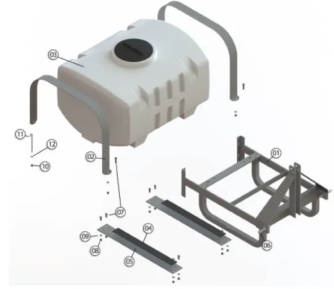
| REF | PART NO | DESCRIPTION | QTY |
| 1 | 32-100080 | 3-Point Frame, 100-200 PCO | 1 |
| 2 | 31-100189 | Tank Strap, PCO-150Gallon | 2 |
| 2 | 31-100190 | Tank Strap, PCO-200 Gallon | 2 |
| 3 | 3-103330 | Tank, 150 Gallon PCO (37x48x29) | 1 |
| 3 | 3-103331 | Tank, 200 Gallon PCO (37x48x38) | 1 |
| 4 | 33-103739 | Anti-Slip Rubber Pad (1/8”x3”x25”) | 2 |
| 5 | 31-100191 | Support Tank, 150/200 3-Point | 2 |
| 6 | 152IP | Implement Pin | 2 |
| 7 | 33-100177 | Bolt (1/2” – 13 x 1.25”) | 10 |
| 8 | 33-100133 | Nut – 1/2”-13 | 14 |
| 9 | 33-100134 | Lock Washer – 1/2” | 14 |
| 10 | 33-100136 | Nyloc Nut – 3/8” | 2 |
| 11 | 33-100072 | J-Bolt | 2 |
| 12 | 33-100130 | 3/8: Washer | 2 |
BOOM PARTS ASSEMBLY
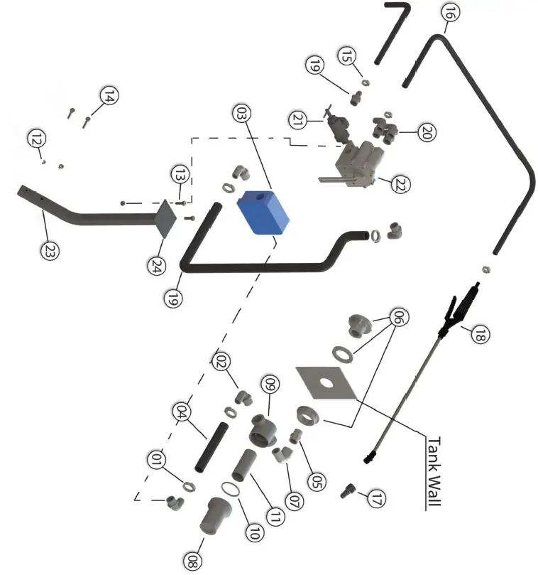
| REF | PART NO | DESCRIPTION | QTY |
| 1 | SHC-M | Snapper Hose Clip, BLK | 4 |
| 2 | 3EL34 | Elbow: 3/4” MPT x 3/4” HB Poly | 4 |
| 3 | 6 Roller Pump | – Sold Separately – | – |
| 4 | 33-103623 | Rubber Hose 3/4” ID Braided | 1 |
| 5 | 3M34 | Nipple 3/4” MPT x 3/4” MPT Poly | 1 |
| 6 | BHF34 | Bulk Head Fitting | 1 |
| 7 | 3SE34 | Straight Elbow 3/4” MPT x 3/4” FPT | 1 |
| 8 | 11278 | Bowl-Reg Poly Black GF | 1 |
| 9 | 11317 | Top 3/4” Poly Black GF | 1 |
| 10 | 11302 | 3/8”, 1/2” & 3/4” Gasket-EPDM | 1 |
| 11 | 10684 | Cyl. Reg ILS 50*36 SS w/Hem | 1 |
| 12 | 33-100113 | Nut 5/16” SF | 4 |
| 13 | 33-100116 | Bolt 5/16” – 18 x 1” | 2 |
| 14 | 33-100119 | Bolt 5/16” – 18 x 1.75” | 2 |
| 15 | SHC-F | Snapper Hose Clip, BLK | 3 |
| 16 | 33-103622 | Hose 1/2” ID x 13/16” OD EPDM Braided | 1 |
| 17 | SG-45ASSY-18 | Nozzle | 1 |
| 18 | SG-405F | Gun, Wand Sprayer with Filter | 1 |
| 19 | 3A3412 | Straight: 3/4” MPT x 1/2” HB Poly | 2 |
| 20 | 3EL3412 | Elbow: 3/4” MPT x 1/2” HB Poly | 3 |
| 21 | RV Valve | 1 | |
| 22 | 33-103290 | Tee-Valve, 7 Selection Setting | 1 |
| 23 | 31-101065 | Post, Boom Control | 1 |
| 24 | 31-101064 | Plate, Boom Control | 1 |
FIGURE 34-140127
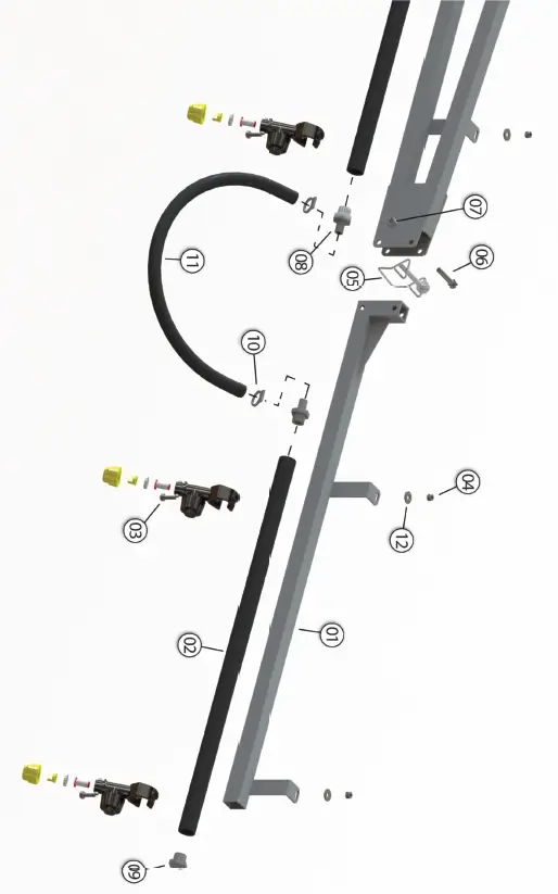
| REF | PART NO | DESCRIPTION | QTY |
| 1 | 31-1011042 | Pipe, Center 85” | 1 |
| 2 | 31-101043 | Pipe, Left & Right 55” | 2 |
| 3 | 32-101012 | Weldment, Center | 1 |
| 4 | 32-101013 | Weldment, Left | 1 |
| 5 | 32-101015 | Weldment, Right | 1 |
| 6 | 3A12 | Straight: 1/2” MPT x 1/2” HB | 3 |
| 7 | 33-100423 | Nut, Nylon Lock M6 | 13 |
| 8 | 33-100422 | Bolt, Hex Head, M6 x 16mm | 13 |
| 9 | 3F12 | Hex Plug: 1/2” MPT Poly | 3 |
| 10 | 3EL12 | Elbow: 1/2” MPT x 1/2” HB | 1 |
| 11 | G-8234009 | Nozzle Holder, Hinged | 13 |
| NS-50 | Strainer, Nozzle 50 Mesh | 13 | |
| G-G00002020 | Gasket For Caps | 13 | |
| G-8259054 | Flat Spray Tip, 110 DEG, (Blue) | 13 | |
| G-T00100001 | Cap Only, Fits Flat Spray Tips | 13 | |
| 12 | 33-100142 | Spring, Compression 1.25” OD | 2 |
| 13 | 33-103622 | Hose, 1/2” ID x 13/16” OD | 321” |
| 14 | SHC-H | Snapper Hose Clips | 6 |
| 15 | 32-101017 | Weldment, Pin | 2 |
| 16 | 33-100424 | Collar 1/2” | 2 |
| 17 | 33-100127 | Cotter Pin | 2 |
| 18 | 33-103131 | Washer #10 Zinc | 13 |
| 19 | 33-100425 | Washer 1/2” ID, 1.375” OD | 6 |
| 20 | 31-101066 | Bracket, Boom Support (Not Shown) | 2 |
| 21 | 33-100163 | U Bolt, Square (Not Shown) | 4 |
| 22 | 33-100113 | Nut, 5/16” Serrated Flange (Not Shown) | 8 |
| REF | PART NO | DESCRIPTION | QTY |
| 1 | 32-101014 | Boom, 28 Ft Left Wing | 1 |
| 32-101016 | Boom, 28 Ft Right Wing | 1 | |
| 2 | 31-101044 | Pipe 25” | 1 |
| 3 | 33-100422 | Bolt, M6 x 16mm, Hex Head | 2 |
| 4 | 33-100423 | Nut, Nylon M6 | 2 |
| 5 | 904PA | Lock Pin 5/16” | 1 |
| 6 | 33-100119 | Bolt 5/16” x 1.75” | 1 |
| 7 | 33-100120 | Lock Nut 5/16” | 1 |
| 8 | 3A12 | Straight: 1/2” MPT x 1/2” HB | 2 |
| 9 | 3F12 | Hex Plug: 1/2” MPT Poly | 1 |
| 10 | SHC-H | Snapper Hose Clip | 2 |
| 11 | 33-103622 | 1/2” Hose, 1/2” ID x 13/16” OD | 15 |
| 12 | 33-103131 | Washer #10 Zinc | 2 |
| 13 | G-8234009 | Nozzle Holder, Hinged | 2 |
| G-8259054 | Spray Tip, 110 Deg. | 2 | |
| G-T00100001 | Nozzle Cap | 2 | |
| G-G00002020 | Nozzle Gasket | 2 | |
| NS-50 | Nozzle Strainer | 2 |


